manuals.online logo
Brands
  1. Home
  2. •
  3. Brands
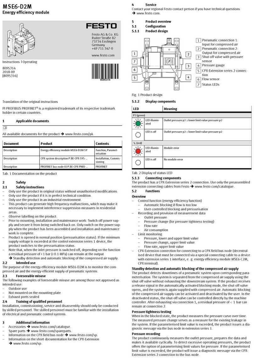
  4. •
  5. Festo
  6. •
  7. Control Unit
  8. •
  9. Festo CPX-FVDA-P2 User manual

Festo CPX-FVDA-P2 User manual

Translation of the original instructions
PI PROFIBUS PROFINET®, PROFIsafe® are registered trademarks of the respective
trademark owners in certain countries.
1 Safety instructions
Installation and commissioning must be carried out only by properly qualified per
sonnel in accordance with these operating instructions.
WARNING!
Nonobservance of safety regulations can result in death, serious injuries or major
material damage.
• The safety instructions must be observed.
NOTICE!
Electronics modules include electrostatically sensitive devices.
Incorrect handling can cause damage to the electronics modules.
• Observe the handling specifications for electrostatically sensitive devices.
• Discharge static electricity from your body before assembling or disas
sembling modules to protect the modules.
NOTICE!
To ensure compliance with the intended use:
• Each output channel that is in use must be switched at least once a week.
• If test pulses are switched off:
Each output that is in use must be switched at least once a day.
NOTICE!
To ensure compliance with the safety level:
• Each output channel that is in use must be switched on for more than
1minute at least once every 8operating hours.
The operating time begins when the output module is first switched on.
NOTICE!
• Use a maximum of 2output channels in a common safety pilot circuit.
Observe the regulations for providing voltage (protective extralow voltage, PELV)
to CPX terminals in the system description CPXSYS… èwww.festo.com/sp
1.1 Symbols
Identification of dangers and notes on how to avoid them:
WARNING!
Dangers which can lead to death or serious injuries.
CAUTION!
Dangers which can lead to slight injuries or to serious material damage.
Other symbols:
NOTICE!
Material damage or loss of function
Recommendation or tip
ENVIRONMENT!
Information on environmentally friendly use
Link to accessories èwww.festo.com/catalogue
1.2 Intended use
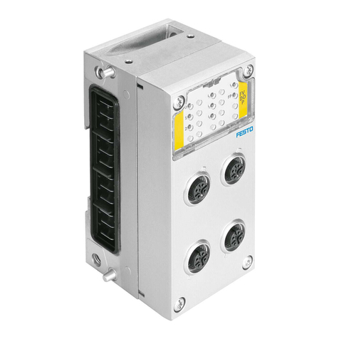
The output module CPXFVDAP2 is used correctly as a shutoff module for the
safe shutdown of connected consumers (safety function) if the following condition
is met:
– The connected consumers go into a safe state when the safety shutdown
takes place.
Product versions
The output module CPXFVDAP2 is available in three versions
è Tab. 4 Permissible components:
– Version 1
in combination with certain manifold and interlinking blocks of the CPX ter
minal
– Version 2
as part of the pneumatic interface VABAS61X...F1CB of the valve terminal
VTSAFCB
– Version 3
as part of the pneumatic interface VABAS61X...F2CB of the valve terminal
VTSAFCB
Safety function
The safety function is achieved through dualchannel, P and Mside disconnec
tion of the load voltage supply for UVAL valves:
– Version1
– Disconnection of the load voltage supply for UVAL valves of the CPX ter
minal: output channel CH0 of the module.
Output channel CH0 is used to supply valve terminal pneumatic modules
in the CPX terminal fitted on the righthand side.
– Disconnection of the two outputs provided through the connection tech
nology of the module: output channel CH1 and CH2 of the module, also
supplied via the load voltage supply for UVAL valves.
In addition, the unswitched load voltage supply UVAL is made available
through the connection technology of the module as operating voltage for the
external components (24VDC auxiliary supply).
– Version2
– Disconnection of the three internal safe voltage zones: CH0, CH1, CH2.
– Version 3
– Disconnection of the two internal safe voltage zones: CH0, CH1.
– Disconnection of the safe output provided through the connection tech
nology of the pneumatic interface: CH2.
The voltage zones can be disconnected independently of each other in an
electrically safe manner.
The output channels of the output module CPXFVDAP2 each form a safety circuit
with their connected consumers.
Information about the power supply for the CPX terminal èSystem description
CPXSYS...
Range of application
The output module CPXFVDAP2 is a product with safetyrelevant functions and is
intended for installation in machines or automation systems and for use as fol
lows:
– In excellent technical condition
– In its original condition, without unauthorised modifications
– Only in the configurations named in the description CPXFVDAP2...
– Within the limits of the product defined by the technical data
è 7 Technical data
– In an industrial environment
NOTICE!
Note that the safety limits of the output module are also its physical limits.
1.3 Rules for product configuration
– Operation of the output module CPXFVDAP2 is permissible only in CPX ter
minals from Festo of the variant CPXM... or in pneumatic interfaces for the
valve terminal VTSAFCB...
– Comply with all technical operating limits è 7 Technical data. Otherwise,
malfunctions can occur.
– Operation of the CPXFVDAP2 is permissible only in combination with the fol
lowing PROFIsafecompatible CPX bus nodes èBus node rating plate:
Bus node From revision Network protocol
CPXFB131) 30 PROFIBUS
CPXFB332) 21 PROFINET IO
CPXMFB342) 21 PROFINET IO
CPXMFB352) 21 PROFINET IO
1) èDescription CPXFB13...
2) èDescription CPXPNIO...
Tab. 1 Permissible PROFIsafecompatible CPX bus nodes
8076421
CPX-FVDA-P2
Output module
8076421
201810b
[8076423]
Brief description
Festo AG & Co. KG
Ruiter Straße 82
73734 Esslingen
Germany
+49 711 3470
www.festo.com
– Operation of the CPXFVDAP2 within valve terminals is only permissible with
the following valve types:
Valve terminal Type Valve types
MPASFBVI 32 MPA1, MPA2 on VMPA…FBEMG…1)
MPAFFBVI 33 MPAF1, MPAF2 on VMPA…FBEMG…1)
VTSAFBVI 44 All up to width of 52mm1)
VTSAFFBVI 45 All up to width of 52mm1)
VTSAFCBVI 46 All1)
1) Malfunctions may occur if the resultant current is exceeded.
Tab. 2 Permissible valve types
– Operation of shutoff groups within valve terminals is only allowed in conjunc
tion with permissible pneumatics èDescription of the respective valveter
minal.
– Operation of shutoff groups in CPX terminals in the RemoteI/O operating
mode is only allowed with the following approved output modules:
Output module
CPX4DA1)
CPX8DA1)
CPX8DAH1)
CPX8DE8DA1)
1) Malfunctions may occur if the resultant current is exceeded.
Tab. 3 Permissible output modules
– Only the following components are permitted when assembling the CPX
FVDAP2:
Version Component Type
Interlinking block CPXMGEEVFVO
CPXMAB4M12X25POL
1 CPXFVDAP2 in combination
with certain manifold and
interlinking blocks of the
CPX terminal
Manifold block
CPXAB8KL4POL
2 Pneumatic interface VABAS61X...F1CB
3
CPXFVDAP21) as part of the
pneumatic interface of the
valve terminal VTSA‑F‑CB Pneumatic interface VABAS61X...F2CB
1) RevisionR04 (or a higher revision) of the output module required èRating plate of the electronics mod
ule CPX‑FVDA‑P2
Tab. 4 Permissible components
Further information about the supported product versions can be found in the
description CPXFVDAP2... and the description of the valve terminal VTSAFCB.
Detailed information about the product, the supported product versions and
required software versions as well as the permissible components of the CPX ter
minal can be found in the system description CPXSYS… èwww.festo.com/pk.
Information about permissible configurations of the CPX terminal in combination
with the output module can be found in the catalogue
èwww.festo.com/catalogue.
1.4 Foreseeable misuse
The following examples of foreseeable misuse are among those not approved as
intended use:
– Use outdoors
– Use in nonindustrial areas
– Use outside the limits of the product defined in the technical data
– Unauthorised modifications
– Use in combination with consumers where switching off can result in hazard
ous movements or conditions
NOTICE!
The use of manifold blocks, interlinking blocks and pneumatic interfaces that are
not specified is not permissible.
NOTICE!
In the following cases, the use of the output module CPXFVDAP2 for formation of
safety circuits is not permissible:
• In a CPX terminal equipped with CPXFEC or CPXCEC
• In a CPX terminal with shutoff groups containing output modules other than
those permitted
• In a CPX terminal of variant P
• In a CPX terminal with a connected valve terminal which is equipped with
valve types other than the following: VTSA, MPAS, MPAF
è Tab. 2 Permissible valve types
• In a CPX terminal with a connected valve terminal where a proportionalpres
sure regulator VPPM is located in switching groups with a safety shutdown
function
• In impermissible switching configurations èDescription CPXFVDAP2...
NOTICE!
The output module does not contain any wearing parts. Repairs are not allowed
on the output module CPXFVDAP2. This invalidates the certification of the out
put module. Professional replacement of the electronics module by the user is
permissible.
NOTICE!
In the event of damage caused by unauthorised manipulation or any form other
than the intended use, the warranty is invalidated, and the manufacturer is not
liable for damages.
1.5 Attainable safety level
With the CPXFVDAP2, safety functions can be implemented up to:
– Safety integrity level SIL3 in accordance with IEC61508
– Performance Level e, Cat. 3 in accordance with ENISO138491
– SIL claim limit SILCL3 in accordance with EN62061.
The attainable safety level of the overall safety device depends on the other com
ponents used to implement the safety function.
To maintain the safety level:
– Test the functionality of the safety device at adequate intervals.
1.6 Failures due to a common cause (Common Cause Failure – CCF)
Common cause failures cause the loss of the safety function, since both channels
(P and M) in a dualchannel system fail simultaneously.
The following measures ensure that common cause failures are avoided:
– Comply with operating voltage limits
– Comply with temperature range
è Tab. 16 Further characteristic values
è Fig.7
– Use a maximum of 2output channels in a common safety pilot circuit
Additional measures for avoidance of common cause failures may result from the
application.
1.7 Requirements for product use
– Make this brief description available to the design engineer, installation tech
nician and personnel responsible for commissioning the machine or system in
which this product is used.
– Keep this brief description throughout the entire product lifecycle.
– Make sure that the specifications of the documentation are always complied
with. Also comply with the documentation for the other components and
modules (e.g. bus nodes, pneumatics, etc.).
– Take into consideration the legal regulations applicable for the location as
well as:
– Regulations and standards
– Regulations of the testing organisations and insurers
– National specifications
– Remove all packaging, such as foils, caps, cardboard. The material used in
the packaging has been specifically chosen for its recyclability (exception:
oiled paper = residual waste).
– Assembly must be performed in a professionally correct manner. To maintain
the IP degree of protection:
– Screw the manifold block on tight
è 4.3 Assembling the electronics module.
– Mount cable entry and seals in a professionally correct manner.
– Seal unused ports with cover caps.
– If the system had to be shut down for safety reasons such as an emergency
stop, make sure the safety controller monitors/controls all system restarts.
1.8 Technical prerequisites
General conditions for the correct and safe use of the product, which must be
observed at all times:
– Comply with the technical operating limits è 7 Technical data.
Only then is operation of the product ensured in accordance with the relevant
safety regulations.
– When connecting standard auxiliary components, also observe the specified
critical limits for temperatures, electrical data and torques.
1.9 Training of skilled personnel
The device may only be commissioned by trained, qualified control and automa
tion technology personnel, who are familiar with:
– Installation and operation of control systems
– Applicable regulations for operating safetyrelated systems
– Applicable regulations for accident prevention and occupational safety
– The documentation for the product
NOTICE!
Work on safetyrelated systems may only be carried out by qualified personnel
trained in safety engineering.
1.10 Transport and storage conditions
– Protect the product during transport and storage from excessive stress
factors, such as:
– Mechanical loads
– Impermissible temperatures
– Moisture
– Aggressive atmospheres
– Store and transport the product in its original packaging.
The original packaging offers sufficient protection from typical stresses.
1.11 Service
Please consult your local Festo service if you have any technical problems.
1.12 Range of application and certifications
This product is a safety device as defined in the EU Machinery Directive and car
ries the CE marking.
Standards and test values, which the product must comply with and fulfil, can be
found in the section “Technical data”. The productrelevant EC directives can be
found in the declaration of conformity. Certificates and the declaration of con
formity for this product can be found at www.festo.com.
– Please note that compliance with the named standards is limited to the out
put module CPXFVDAP2. From the perspective of the output module, all dis
connectable parts of a CPX terminal and/or valve terminal are treated as an
external load.
Certain configurations of the product have been certified by Underwriters Laborat
ories Inc. (UL) for the USA and Canada.
These configurations bear the following mark:
UL Recognized Component Mark for Canada and the United States
Only for connection to an NEC Class 2 supply.
Raccorder Uniquement a un circuit de Classe 2.
NOTICE!
Observe the following if the UL requirements are to be complied with in your
application:
• Regulations for complying with the UL certification can be found in the separ
ate ULspecific special documentation.
The relevant technical data in that documentation also apply with priority if
they do not influence the safety characteristic values in an impermissible
manner.
• The technical data in this documentation may show values deviating from
this.
2 Product identification
The module identifier and product rating plate serve to identify the product. The
module identifier can be seen through the transparent cover of the manifold
block/the cover for the pneumatic interface.
Module identifier Meaning
– Module identifier 1: FVDOP2
(F=Safety; V=Valves; D=Digital;
O=Outputs; P=PROFIsafe; 2=Variant)
Tab. 5 Module identifier of the output module CPXFVDAP2
The rating plate of the electronics module CPXFVDAP2 (è Fig.1) shows the fol
lowing information:
Rating plate (example) Meaning
Rating plate
– Order reference 1
– Part number 21)
– Revision code (here R01) 3
– Serial number shown as a data matrix code
42)
– Manufacturer and manufacturer’s address
5
– 14character serial number 62)
– Manufacturing period (encoded, here A5=
May2010) 73)
1) Part number of the electronics module CPXFVDAP2
2) Makes it possible to trace the product.
3) èDescription CPXFVDAP2…
Tab. 6 Rating plate of the electronics module CPXFVDAP2
Additional information can be found in the system description CPXSYS…
èwww.festo.com/sp
This brief description applies to the following product
Type Part number Revision
CPXFVDAP2 1971599 R0x1)
è Rating plate of the electronics module CPX
FVDAP23
1) x stands for a single digit from 1to9
Tab. 7 Applicability
• Before replacing a module, check whether the revision of the bus node cor
responds to the requirements of the electronics module
è Tab. 1 Permissible PROFIsafecompatible CPX bus nodes.
• For the pneumatic interface VABAS61X...F1/F2CB, only use an electronics
module with revision R04 (or higher) è Tab. 4 Permissible components.
3 Connection and display components
3.1 Design of the output module in a CPX terminal
1Manifold block
CPXMAB4M12X25POL
2Manifold block CPXAB8KL4POL
3Electronics module CPXFVDAP2
410way DIL switch for PROFIsafe
address
5Mechanical coding
6Interlinking block with contact rails
CPXMGEEVFVO
7Rating plate (underneath)
8Electrical plug connection
betweenelectronics module and
manifold block
9LEDs of the electronics module
10 Screws
Fig. 1 Output module CPXFVDAP2 in a CPX terminal
3.2 Design of the output module in a valve terminal VTSA-F-CB
1Cover (here VABAS61X2F2CB)
2M12 bushing (version3 only,
VABAS61X2F2CB)
3Electronics module CPXFVDAP2
410way DIL switch for PROFIsafe
address
5Pneumatic interface
6Housing with contact rails for
electronics module
7Rating plate (underneath)
8Electrical plug connection
between electronics module and
cover with M12 bushing
9LEDs of the electronics module
10 Screws
Fig. 2 Output module CPXFVDAP2 in a pneumatic interface VABAS61X...
F1/F2CB of the valve terminal VTSAFCB
4 Installation
WARNING!
• For the electrical power supply, use only PELV circuits in accordance with
EN602041 (protective extralow voltage, PELV).
Also take into account the general requirements for PELV circuits in accord
ance with EN602041.
• Only use power sources which guarantee reliable electrical isolation of the
operating voltage from the mains in accordance with EN602041.
Through the use of PELV circuits, protection from electric shock (protection from
direct and indirect contact) in accordance with EN602041 is ensured (Electrical
equipment of machines. General requirements).
Compliance with the input voltage limits of the module is also ensured.
NOTICE!
Electronics modules include electrostatically sensitive devices.
• Observe the handling specifications for electrostatically sensitive devices.
• Discharge static electricity from your body before assembling or disas
sembling modules to protect the modules.
NOTICE!
The crosscircuit monitoring function monitors the device’s own circuits.
• Ensure that crosscircuiting to other circuits is not possible using appropriate
installation measures.
• Ensure that defective cables are replaced immediately.
– Switch off the supply voltage before assembly or installation.
– Switch on the electrical supply voltage only when the product is completely
assembled, and all installation work is finished.
4.1 Setting the PROFIsafe address
To allow communication via PROFIsafe, the correct PROFIsafe address must be set
with binary coding on the output module via the 10way DIL switch
(è Tab. 8 10way DIL switch of the electronics module).
PROFIsafe addresses in the range from 1to1023 are permissible.
NOTICE!
This PROFIsafe module accepts every PROFIsafe host address and thus fulfils the
requirements for PROFIsafe address type1.
The 10way DIL switch is located directly on the electronics module and can be set
while the manifold block or the cover of the pneumatic interface is not mounted.
10-way DIL switch Addressing example
1
2
4
8
16
32
64
128
256
512
2 + 64 + 512 = 578
Tab. 8 10way DIL switch of the electronics module
NOTICE!
The DIL switch is a mechanically sensitive component due to its size.
• To set it, use an appropriate, small blunt tool (e.g. watchmaker’s screwdriver)
and proceed very carefully.
1. Switch off the power supplies of the CPX terminal.
2. Remove the mounted manifold block (è Fig.1) or the cover of the pneumatic
interface (è Fig.2).
3. Carefully set the DIL switch.
4. Remount the manifold block or the cover of the pneumatic interface
è 4.3 Assembling the electronics module.
4.2 Dismounting the electronics module
NOTICE!
Incorrect handling can damage the electronics module.
• Never pull the electronics module out of the interlinking block or the pneu
matic interface when powered.
To avoid errors in assembly, both the interlinking block CPXMGEEVFVO and the
electronics module CPXFVDAP2 are mechanically coded. The coding prevents a
different module from being plugged into the interlinking block or the module
from being plugged into an incorrect interlinking block.
The plugs connected to the manifold block can remain attached during dismount
ing of the manifold block.
To dismount:
1. Switch off the operating and load voltage supplies.
2. Unscrew the screws aJ and carefully lift off the manifold block 1 or 2
(è Fig.1) or the cover of the pneumatic interface 1 (è Fig.2).
3. If necessary: pull the electronics module 3 carefully off the contact rails/the
contacts in the pneumatic interface or out of the manifold block.
4.3 Assembling the electronics module
NOTICE!
Incorrect handling can damage the electronics module.
• Never push the electronics module into the interlinking block or the pneumat
ic interface when powered.
NOTICE!
• Ensure that the interlinking block (è Fig.1) or the housing of the pneumatic
interface (è Fig.2) is clean and free of foreign matter, especially on and near
the contacts and contact rails.
• Check the seals for damage in order to comply with the degree of protection
IP65/IP67.
• Make sure that connecting surfaces are clean in order to optimise the sealing
effect and prevent contact errors.
NOTICE!
• Use only the supplied screws with metric threads for the metal interlinking
block CPXMGEEVFVO.
• Use only the supplied selftapping screws for the pneumatic interface.
• To avoid damaging the threads, make sure the screws are inserted precisely
and use existing threads.
• Tighten the screws using a handheld screwdriver only.
• Make sure that threaded fittings are free of any distortion or mechanical ten
sion.
• For modules and components ordered at a later date, observe the assembly
instructions in the documentation that comes with the products.
For assembly:
1. Switch off the operating and load voltage supplies.
2. Align the electronics module 3 correctly and press it carefully into the inter
linking block 6 (è Fig.1) or into the housing 6 (è Fig.2).
3. Check the seal and the sealing surfaces, align the manifold block 1 or 2 or
the cover of the pneumatic interface and place it on the electronics module
3.
4. Set the screws aJ so that the existing threads can be used. Tighten the
screws by hand in diagonally opposite sequence.
Tightening torque: 0.9 ... 1.1Nm.
4.4 Pin allocation
CPX-FVDA-P2 with manifold block CPX-M-AB-4-M12X2-5POL
Pin allocation X1, X2 Pin allocation X3, X4
2
3
1
5
4
X1
Bushing X1
1: 0V CH11)
2: +24V CH11)
3: F–DO(M) CH12)
4: F–DO(P) CH12)
5: FE
2
3
1
5
4
X3
Bushing X3
1: n.c.
2: n.c.
3: n.c.
4: n.c.
5: FE
2
3
1
5
4
X2
Bushing X2
1: 0V CH21)
2: +24V CH21)
3: F–DO(M) CH22)
4: F–DO(P) CH22)
5: FE
2
3
1
5
4
X4
Bushing X4
1: n.c.
2: n.c.
3: n.c.
4: n.c.
5: FE
FE = functional earth
n.c. = free (not connected)
1) Unswitched voltage UVAL usable for supply of intelligent load systems (auxiliary supply)
2) All output voltages are likewise derived from the internal contact rail UVAL.
Tab. 9 CPXFVDAP2 with manifold block CPXMAB4M12X25POL
The metal thread of the manifold block CPXMAB4M12x25POL is connected
internally with pin 5 (functional earth FE).
CPX-FVDA-P2 with manifold block CPX-AB-8-KL-4POL
Pin allocation X1, X2, X3, X4 Pin allocation X5, X6, X7, X8
X1
0: 0V CH11)
1: F–DO(M) CH12)
2: F–DO(P) CH12)
3: FE
X5
0: n.c.
1: n.c.
2: n.c.
3: FE
X2
0: n.c.
1: n.c.
2: +24V CH11)
3: FE
X6
0: n.c.
1: n.c.
2: n.c.
3: FE
X3
0: 0V CH21)
1: F–DO (M) CH22)
2: F–DO (P) CH22)
3: FE
X7
0: n.c.
1: n.c.
2: n.c.
3: FE
X4
0: n.c.
1: n.c.
2: +24V CH21)
3: FE
X8
0: n.c.
1: n.c.
2: n.c.
3: FE
CPX-FVDA-P2 with manifold block CPX-AB-8-KL-4POL
Pin allocation X1, X2, X3, X4 Pin allocation X5, X6, X7, X8
FE = functional earth
n.c. = free (not connected)
1) Unswitched voltage UVAL usable for supply of intelligent load systems (auxiliary supply)
2) All output voltages are likewise derived from the internal contact rail UVAL.
Tab. 10 CPXFVDAP2 with manifold block CPXAB8KL4POL
CPX-FVDA-P2 in pneumatic interface VABA-S6-1-X...-F2-CB
Pin allocation external channel CH2 on M12 bushing
2
3
1
5
4
X1
M12 bushing
1: 0V CH21)
2: +24V CH21)
3: F–DO(M) CH22)
4: F–DO(P) CH22)
5: FE
FE = functional earth
1) Unswitched voltage UVAL usable for supply of intelligent load systems (auxiliary supply)
2) All output voltages are likewise derived from the internal contact rail UVAL.
Tab. 11 CPXFVDAP2 in pneumatic interface VABAS61X...F2CB
5 Commissioning
5.1 Start behaviour of the output module
The following LEDs for onsite diagnostics are located under the transparent cover
of the module:
1Module error LED (red)
2FP LED (green) – Failsafe Protocol
3Channel error LED (red);
one for each output channel
4Status LED (yellow);
one for each output channel
Fig. 3 LED display of the output module CPXFVDAP2
NOTICE!
The LED indicator of the module was not designed for safety purposes.
• Please note that these LEDs should not be used for evaluation during safety
related activities.
When the operating voltage supply UEL/SEN is switched on, the module error LED
1 lights up for approx.500ms.
When the load voltage supply UVAL is switched on, the channel error LEDs 3
light up for approx.1s.
The supplies can be switched on in any order as far as the output module is con
cerned.
If both power supplies are switched on simultaneously, the specified LEDs light
up together.
The FP LED flashes until the output module is correctly parameterised by means
of a PROFIsafe master.
After correct parameterisation, the FP LED lights up and the module is ready for
operation.
During normal operation status, the following LEDs light up:
– FP LED – Failsafe Protocol 2 (green)
– Status LED4 of the active output channels (yellow)
The status LEDs of inactive output channels and the module and channel error
LEDs do not light up.
NOTICE!
• Test the functionality of the safety device at adequate intervals.
Selecting the type of test and time intervals between the tests is the responsibility
of the operator.
The manner in which the test is conducted must make it possible to verify that the
safety device is functioning perfectly in interaction with all components.
Additional information can be found in the system description CPXSYS…
èwww.festo.com/sp
6 Service, repair, disposal
The output module does not contain any components requiring servicing.
NOTICE!
The module does not contain any wearing parts. Repairs are not allowed.
This invalidates the certification of the output module.
A professional replacement of the electronics module is permissible.
NOTICE!
• Always replace the output module in case of an internal defect.
• Send the unmodified defective output module, including a description of the
error and the application, back to Festo for analysis.
Please contact your technical consultant to clarify the modalities of the return.
When making your complaint, you should mention that the module is a safety
device.
For final disposal of the output module, please contact a certified waste manage
ment company for electronic waste.
7 Technical data
General technical data of the CPX terminal èSystem description CPXSYS...
Electrical characteristic values CPX-FVDA-P2
Nominal operating voltage [VDC] 24
Permissible voltage fluctuations [%] –15 … +20
Operating voltage when tapping contact rail
24VVAL and 0VVAL (integrated reverse polarity
protection)
[VDC] 20.4 … 28.8
Residual ripple (within tol.) [Vss] 2
Voltage drop bypass time UVAL [ms] 2
Intrinsic current consumption at nominal operat
ing voltage
[mA] typ.65 for valves (from UVAL)
typ.25 for electronics (from UEL/SEN)
Undervoltage monitoring UVAL [V] <19.5 for t>250ms
Overvoltage monitoring UVAL [V] >29.5 for t>250ms
Electrical isolation between VEL/SEN (or 5V CBUS)
and VVAL
[V rms] Min.500
Electrical isolation between output channel
(CH0, CH1, CH2) – and internal bus
Yes, with intermediate supply
Electrical isolation between output channel and
– output channel
No
Potential reference of the output channels UVAL
Max. power supply CH0, CH1, CH2 (load current
per output channel)
[A] 1.5
è Fig.7
Max. load current per unswitched voltage UVAL
(auxiliary supply)
[A] 2.5
Max. peak current per output channel [A] 5 for t<30ms
Max. resultant current per module [A] 5
Max. switching frequency of the output channels [Hz] 1
Max. voltage drop per output channel under con
tinuous load
[V] 0.6
Wire break detection (CH0, CH1, CH2) Can be parameterised, detection
point IL approx.50mA1)
Max. cable length (CH1, CH2) [m] 200
Max. load capacity against FE [nF]
400
Max. load capacity PM [μF]
22
Max. load inductivity [mH] 1000 at 150mA, 100 at 600mA;
Characteristic curve
è Fig.4
Fuse protection (short circuit) Integrated electronic fuse
Max. test pulse duration [μs] 300
Max. voltage drop during test pulse [V] 6
1) When using the output module in the pneumatic interface – without external voltage zones – deactivate
wire break detection.
Tab. 12 Electrical characteristic values
Fig. 4 Maximum permissible load inductivity at the output channels
Functional characteristic values CPX-FVDA-P2
Module code 193d (C1h)
Submodule code 8d (08h)
Compatible with fast startup (FSU) Yes
Startup time until module ready [s] <2
Diagnostics of external channel fault Periodic inspection
– for function
– for external supply
– for cross circuit
Response time for external channel errors [min] <1
Response time to switch off command (typ.) [ms] <10
Internal PROFIsafe processing time (TDAT) [ms] <50
Tab. 13 Functional characteristic values
Safety characteristics1) CPX-FVDA-P2
Safety function Safe shutdown of the output chan
nels
– in accordance with IEC61508
with SIL3
– in accordance with
ENISO13849
with Cat.3, PLe
– in accordance with EN62061
with SILCL3
Shutdown schema for each output channel P and Mswitching
Internal response time to switch off command
(TWCDT) on output channel CH0
[ms] <23
Internal response time to switch off command
(TWCDT) on output channels CH1 and CH2 depend
ing on minimum load
Load diagrams
è Fig.5
è Fig.6
PROFIsafe watchdog time [ms] F_WD_TIME
Max. response time of safety function [ms] F_WD_TIME + TWCDT
Max. cyclical request rate [1/min] 1
Mean time to dangerous failure (MTTFd) [years] >750
Probability of a dangerous failure per hour
(PFHD)
[1/h] <1.0 x 10⁻⁹
Max. useful life [years] 20
Min. request rate for each output channel (CH0,
CH1, CH2)
[1/week] 1
Measures to avoid common cause failures (CCF) – Comply with operating voltage
limits
– Comply with temperature
range
è Tab. 16 Further
characteristic values
è Fig.7
– Combine a maximum of 2out
put channels in a common
safety pilot circuit
Safety protocol PROFIsafeprofile version2.42)
Type test The functional safety engineering of
the product has been certified by an
independent testing body èEC
type examination certificate
èwww.festo.com.
CE marking (èdeclaration of conformity) To EU Machinery Directive
Certificate issuing authority TÜV(German Technical Control
Board) Rheinland
01/205/5294.01/18
1) In order to guarantee the safety level, a minimum switchon period of 1minute must be ensured every
8operating hours for each output channel used.
2) Profile for Safety Technology on PROFIBUSDP and PROFINETIO; version 2.4, March 2007
Tab. 14 Safety characteristics
NOTICE!
• Use the following graph if the load current is known.
TWCDT [ms]
ILast [mA]
Fig. 5 Internal response time as a function of the minimum load current
NOTICE!
• Internal response time as a function of the resistive minimum load
TWCDT [ms]
RLast [Ohm]
Fig. 6 Internal response time as a function of the resistive minimum load
Deviating safety characteristic values when test pulses are switched off1)
Min. request rate for each output channel (CH0,
CH1, CH2)
[1/day] 1
1) With the exception of the values specified here, the safety characteristic values retain their validity.
Tab. 15 Deviating safety characteristic values when test pulses are switched off
Further characteristic values
Ambient temperature in storage [°C] – 20 … + 70
Ambient operating temperature
– in interlinking block CPXMGEEVFVO
with resultant current of 4.5A for all 3out
puts
[°C] – 5 … + 50
– in pneumatic interface
VABAS61X...F1/F2CB
with resultant current of 4.5A for all 3out
puts
[°C] – 5 … + 30
– in pneumatic interface
VABAS61X...F1/F2CB
with resultant current of 3A for all 3out
puts
[°C] – 5 … + 40
– in pneumatic interface
VABAS61X...F1/F2CB
with resultant current of 1.5A for all 3out
puts
[°C] – 5 … + 50
Relative humidity (noncondensing) [%] 5 … 90
Degree of protection in accordance with
EN60529
Dependent on the manifold block or
the pneumatic interface1)
Electromagnetic compatibility
– Interference emission
– Immunity to interference
èDeclaration of conformity
èwww.festo.com/sp
UL certification c UL us – Recognized (OL)
1) èDescription CPXFVDAP2... “Technical data of the manifold blocks” or description of the valve terminal
VTSAFCB
Tab. 16 Further characteristic values
Fig. 7 Maximum output current as a function of the ambient temperature (during
operation) when using the output module in the pneumatic interface
VABA‑S6‑1X...F1/F2CB

Other manuals for CPX-FVDA-P2

4

Other Festo Control Unit manuals

Festo CPA VI Series User manual

Festo

Festo CPA VI Series User manual

Festo CPV-DI02 Parts list manual

Festo

Festo CPV-DI02 Parts list manual

Festo VZWM User manual

Festo

Festo VZWM User manual

Festo CDVI5.0 User manual

Festo

Festo CDVI5.0 User manual

Festo CP-FB11-E Parts list manual

Festo

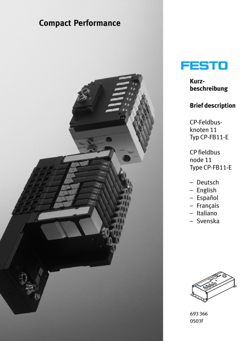
Festo CP-FB11-E Parts list manual

Festo MS6-SV-...-E-10V24 Series User manual

Festo

Festo MS6-SV-...-E-10V24 Series User manual

Festo CMGA-E1-CO User manual

Festo

Festo CMGA-E1-CO User manual

Festo VYKB User manual

Festo

Festo VYKB User manual

Festo CPX-E- AO-U-I Series User manual

Festo

Festo CPX-E- AO-U-I Series User manual

Festo HMP B Z Series User manual

Festo

Festo HMP B Z Series User manual

Festo CP-FB13-E Parts list manual

Festo

Festo CP-FB13-E Parts list manual

Festo Smart cubic CPVSC1-VI User manual

Festo

Festo Smart cubic CPVSC1-VI User manual

Festo MS6-SV Series User manual

Festo

Festo MS6-SV Series User manual

Festo CPX-CMAX-C1-1 Parts list manual

Festo

Festo CPX-CMAX-C1-1 Parts list manual

Festo MPPES Series User manual

Festo

Festo MPPES Series User manual

Festo SPC200-COM-PDP User manual

Festo

Festo SPC200-COM-PDP User manual

Festo CPX-CMIX-M1-1 User manual

Festo

Festo CPX-CMIX-M1-1 User manual

Festo MS6-SV Series User manual

Festo

Festo MS6-SV Series User manual

Festo ZSB-1/8 User manual

Festo

Festo ZSB-1/8 User manual

Festo VPCB T22Series User manual

Festo

Festo VPCB T22Series User manual

Festo HMP-...-SL Series User manual

Festo

Festo HMP-...-SL Series User manual

Festo DW Series User manual

Festo

Festo DW Series User manual

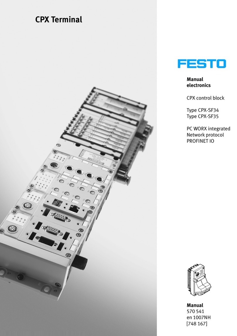
Festo CPX-E-PN User manual

Festo

Festo CPX-E-PN User manual

Festo DLP-VSE-x-ASI eries User manual

Festo

Festo DLP-VSE-x-ASI eries User manual

Popular Control Unit manuals by other brands

Sun Microsystems 2 manual

Sun Microsystems

Sun Microsystems 2 manual

Yale real Living iM1 Installation and programming instructions

Yale

Yale real Living iM1 Installation and programming instructions

Climecon ECO-T instructions

Climecon

Climecon ECO-T instructions

Smartgen HGM6100NC-RM user manual

Smartgen

Smartgen HGM6100NC-RM user manual

Grozone Control TV2 user guide

Grozone Control

Grozone Control TV2 user guide

SamplexPower BBM-12100 owner's manual

SamplexPower

SamplexPower BBM-12100 owner's manual

Gaspardo PRECIMAT USE AND ASSEMBLY INSTRUCTIONS / SPARE PARTS

Gaspardo

Gaspardo PRECIMAT USE AND ASSEMBLY INSTRUCTIONS / SPARE PARTS

ICP DAS USA tDS-700-T Series quick start

ICP DAS USA

ICP DAS USA tDS-700-T Series quick start

Stoneridge SE5000 Process Guide

Stoneridge

Stoneridge SE5000 Process Guide

Dakota Digital DCC-4000 Installation and operator's manual

Dakota Digital

Dakota Digital DCC-4000 Installation and operator's manual

BIRD 4421B540-2 Operation manual

BIRD

BIRD 4421B540-2 Operation manual

Broan VAUTOW Installation and user guide

Broan

Broan VAUTOW Installation and user guide

Trenz Electronic TE0720 Schematics

Trenz Electronic

Trenz Electronic TE0720 Schematics

Honeywell Braukmann DR300 installation instructions

Honeywell

Honeywell Braukmann DR300 installation instructions

Busch-Jaeger SD/U12.55.11-825 manual

Busch-Jaeger

Busch-Jaeger SD/U12.55.11-825 manual

dayLux SET-DLCM3,5 (A,D) Basic user's guide

dayLux

dayLux SET-DLCM3,5 (A,D) Basic user's guide

CustomControls ValveSentry user manual

CustomControls

CustomControls ValveSentry user manual

ZURN TEMP-GARD Z7100 manual

ZURN

ZURN TEMP-GARD Z7100 manual

manuals.online logo
manuals.online logoBrands
  • About & Mission
  • Contact us
  • Privacy Policy
  • Terms and Conditions

Copyright 2025 Manuals.Online. All Rights Reserved.