manuals.online logo
Brands
  1. Home
  2. •
  3. Brands
  4. •
  5. Festo
  6. •
  7. Control Unit
  8. •
  9. Festo MSE6-C2M Parts list manual

Festo MSE6-C2M Parts list manual

Translation of the original instructions
PI PROFIBUS PROFINET® is a registered trademark of its respective trademark
holder in certain countries.
1 Applicable documents
All available documents for the product èwww.festo.com/pk.
Document Product Contents
Description Control and Condition Monitoring Module
MSE6-C2M-SY
Function, Paramet-
erisation
Description CPX system description P.BE-CPX-SYS-... Installation, Commis-
sioning
Description PROFINET bus node IO P.BE-CPX-PNIO-… PROFINET
Tab. 1 Documentation on the product
2 Safety
2.1 Safety instructions
– Only use the product in original status without unauthorised modifications.
– Only use the product if it is in perfect technical condition.
– Only use the product in an industrial environment.
– This product can generate high frequency malfunctions, which may make it
necessary to implement interference suppression measures in residential
areas.
– Observe labelling on the product.
– Prior to mounting, installation and maintenance work: Switch off power sup-
ply and secure it from being switched back on. Only switch on the power sup-
ply when the product has been assembled and installation and maintenance
work is complete.
– Product is opened in normal position (pressurisation status). If the minimum
supply voltage is not reached, the shut-off valve of the product switches to
the pressurisation status.
– Note that, when the inlet pressure is switched off, depending on the function
a residual pressure of < 1 bar (< 0.1 MPa) can remain at the output .
2.2 Intended use
The energy efficiency module MSE6-C2M monitors and optimises the compressed
air consumption via an adjustable outlet pressure.
2.3 Foreseeable misuse
The following examples of foreseeable misuse are among those not approved as
intended use:
– Outdoor use
– Exhaust ports sealed
2.4 Training of qualified personnel
Installation, commissioning, service and disassembly should only be conducted
by skilled personnel. The skilled personnel must be familiar with the installation
of electrical and pneumatic control systems.
3 Additional information
– Accessories èwww.festo.com/catalogue.
– Spare parts èwww.festo.com/spareparts.
– Information on the CPX field bus node èwww.festo.com/sp.
– Information on the short documentation for the CPX-Extension
èwww.festo.com/sp.
4 Service
Contact your regional Festo contact person if you have technical questions
èwww.festo.com.
5 Product overview
5.1 Configuration
5.1.1 Product design
1Pneumatic connection 1:
Input for compressed air
2Pneumatic connection 2:
Output for compressed air
3Shut-off valve with pressure
sensor
4Pressure gauge
5Electrical system supply
6Connection for electrical inputs
7Connection for electrical outputs
8Only MSE6-C2M...-M: connection
for CPX-Extension series 1 for con-
necting devices with CPX-Exten-
sion series 2 connection
9PROFINET bus node CPX-M-FB34
10 Status LEDs
11 Proportional-pressure regulator
12 Flow sensor
Fig. 1 Product design
5.1.2 Display components
LED Meaning
P2 (green)
LED illumin-
ated
Outlet pressure p2 ³ lower critical limit pressure p2
LED flashes Outlet pressure p2 < lower critical limit pressure p2 and
Outlet pressure p2 ³ pressure setpoint auto standby –0.5bar
LED is off Outlet pressure p2 < pressure setpoint auto standby –0.5bar
DI0 and DI1 (green)
LED illumin-
ated
Signal at electrical input 0 or 1 is present (logic 1)
LED is off Signal at electrical input 0 or 1 is not present (logic 0)
DO0 and DI1 (yellow)
LED illumin-
ated
Electrical output 0 or 1 sends 1-signal (logic 1)
LED is off Electrical output 0 or 1 sends 0-signal (logic 0)
P Red
LED illumin-
ated
Module error
LED is off No module error
Tab. 2 Display of status LED
5.1.3 Connecting components
I/O ports for MSE6-C2M
The product has two electrical inputs and two electrical outputs.
8095296
MSE6-C2M
Control and Condition Monitoring Module
8095296
2018-10
[8095298]
Instructions| Operating
Festo AG & Co. KG
Ruiter Straße 82
73734 Esslingen
Germany
+49 711 347-0
www.festo.com
Plug Pin System supply Function
1 24V DC USEN Supply voltage
2 Input-1 Input 1
3 0V USEN 0V load
4 Input-0 Input 0
M12
5 FE Functional earth
Tab. 3 Electrical inputs DI0 and DI1
Plug Pin System supply Function
1 – Not assigned
2 Output-1 Output 1
3 0VA 0V load
4 Output-0 Output 0
M12
5 FE Functional earth
Tab. 4 Electrical outputs DO0 and DO1
I/O and CPX-Extension connections for MSE6-C2M-…-M
The product has two electrical inputs, two electrical outputs and a CPX-Extension
series 1 connection.
Connection Position Plug
Electrical inputs Connections on the cover under
the bus node
Design: M12, 5-pin
Identification: X2
Electrical outputs Connections on the cover under
the bus node
Design: M12, 5-pin
Identification: X1
CPX-Extension Connections on the cover under
the bus node
Design: M12, hybrid, 8-pin
Identification: none
Tab. 5 Electrical inputs, electrical outputs and CPX-Extension
Bus node
The product has a PROFINET bus node CPX-FB34.
Only energy efficiency module MSE6-C2M-...-M
The product has a CPX-Extension series 1 connection. Use only the preassembled
extension connecting cables from Festo èwww.festo.com/catalogue.
5.2 Functions
Overview
– Pressure regulation and blocking function (energy efficiency function)
– Automatic blocking and subsequent regulation to the standby target
pressure with a prolonged reduced flow rate
– User-controlled blocking and pressure regulation
– Parameterisable target pressure rise limitation. (Soft-Start)
– Recording and processing of measurement data
– Outlet pressure P2
– Pressure change (for pressure tightness testing)
– Flow rate
– Air consumption
– Limit monitoring
– Pressure, lower and upper critical limit
– Pressure change, upper critical limit
– Flow rate, upper critical limit
– Electrical I/Os
– 2 digital inputs
– 2 digital outputs
– Channel-based status indicator via LED
– Parameterisable special functions
– Fieldbus connection
– PROFINET connection CPX-FB34
Standby detection and automatic pressure reduction
The product detects downtimes of a pneumatic system upon corresponding para-
meterisation. If the parameterised flow rate critical limit is continuously not
reached during the parameterised delay period, when the automatic function is
activated (controller auto-user and controller auto-enable logic 1), the supply air
is blocked until the parameterised standby target pressure value is reached. The
outlet pressure is then adjusted to this value. This prevents unnecessary exhaust-
ing of the system and enables leakage detection via an analysis of the pressure
drop. A control signal can be used to switch back over from standby pressure reg-
ulation to normal pressure regulation. When the automatic function is deactiv-
ated, the shut-off valve and the pressure regulator can be directly controlled by
the machine controller.
Regulation of the compressed air supply
The product regulates the compressed air supply to the set pressure setpoint.
This can be done in manual mode by the setting from the controller. In automatic
mode, regulation takes place via the parameterised target pressure values. Pre-
requisite: operating pressure P1 ³ target pressure +1bar.
Pressure tightness testing
The product continuously measures the pressure change in the parameterised
time interval and monitors this value to ensure it is not exceeded in the blocking
status. The measured pressure change serves as a measure of the leakage exist-
ing in the downstream system.
Pressure recording
The product continuously measures the outlet pressure, prepares the data and
makes it available cyclically. To detect operating pressures that are too high or
too low, the product offers the option of parameterising critical limits for pres-
sure. If the parameterised critical limit is exceeded, the product will output a dia-
gnostic message. The status of monitoring to ensure the critical limit is not
exceeded is indicated via an input bit and via the P2 LED on the module.
Flow recording
The product continuously records the flow rate, prepares the data and makes it
available cyclically. To detect excessive flow rates, the product offers the option of
parameterising the upper critical limit for the flow rate. If the parameterised critic-
al limit is exceeded, the product will output a diagnostic message.
Consumption recording
The product determines the compressed air consumption by recording the system
flow rate. With the aid of output data, the consumption measurement can be
switched on and off and the consumption value can be reset.
Operational functions
The behaviour of the product can be influenced by accessing the internal para-
meters, e.g.:
– Diagnostic behaviour by enabling maskable diagnostic messages
– Specification of the units and the measuring interval
– Setting of critical limits
The product is delivered with pre-set parameters. Fundamentals of parameterisa-
tion è 8.3 Parameterisation. Detailed information on parameterisation
è 1 Applicable documents.
6 Assembly
The product is intended for wall mounting, e.g. on mounting plates. The mount-
ing brackets are integrated and may not be removed.
Fig. 2 Typical assembly
Prerequisite: the mounting surface is flat and can support the weight of the
product.
1. Adjust the product when it is standing vertically (±5°).
2. Mount the product using the mounting brackets and 2 screws each. Screw
size: M6 If necessary, use washers.
Dimensions
Fig. 3 Dimensions
7 Installation
Installation sequence:
1. Pneumatic connections
2. Earth terminal
3. Electrical connecting cables
7.1 Pneumatic installation
Requirements:
– The product is assembled.
– The contact surfaces must be clean (avoid leakage and contact errors).
• Connect pneumatic connections 1, 2.
7.2 Electrical installation
WARNING!
Risk of injury due to electric shock.
• For the electrical power supply, use only PELV circuits in accordance with IEC
60204-1/EN 60204-1 (Protective Extra-Low Voltage, PELV).
• Observe the general requirements of IEC 60204-1/EN60204-1 for PELV cir-
cuits.
• Only use voltage sources that ensure a reliable electric separation from the
mains network in accordance with IEC 60204-1/EN 60204-1.
For the MSE6-C2M…-M with CPX-Extension series 1 connection, the following
applies:
NOTICE!
Material damage as a result of changing the connecting cable when the supply
voltage is switched on
• Connect and remove the CPX-Extension connecting cable only when the sup-
ply voltage is switched off for the control extension series 1 device.
• Only use pre-assembled connecting cables.
1. Connect the earth terminal.
2. Connect CPX-Extension connecting cable (only for MSE6-C2M…-M)
è 5.1.3 Connecting components.
3. Connect power supply and electrical inputs and outputs.
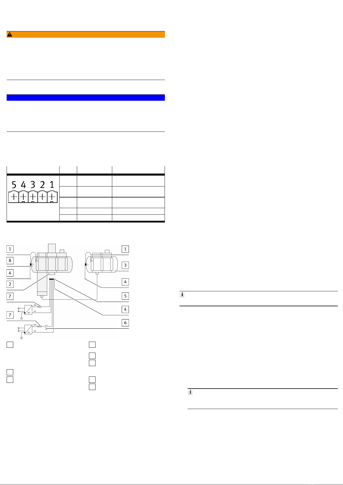
Pin allocation
Plug Pin System supply Function
1 24V DC UEL/SEN Operating voltage supply for
the electronics and sensors
2 0V UEL/SEN Operating voltage of electronics
and sensors
3 24V DC UOUT/A Load voltage supply for actuat-
ors
4 0V UOUT/A Load voltage of actuators
AIDA Push-pull
5 FE Functional earth
Tab. 6 Pin allocation, system supply
Electrical connection example
1Equipotential bonding between
the earth terminal of the left-hand
pneumatic sub-base and the left
end plate of the electrical interlink-
ing module
2System supply
3MSE6-D2M
4Equipotential bonding of function-
al earth (FE)
5Earth terminal pin 5
6Power supply can be separately
disconnected for actuator techno-
logy and electrical inputs
7External fuses
8MSE6-C2M …-M
Fig. 4 Power supply with separate circuits and equipotential bonding
7.3 Combination with MS6 modules
General information
– Maximum permissible number of entire service unit component combina-
tion:10individual modules. The product MSE6-C2M counts as a triple module
here.
– When supplementing MS6 modules, only use the wall mounting MS6-WPG
and the module connector MS6-MV-EX.
– When supplementing MS6 modules, the screws on the module connector
between the flow sensor, proportional-pressure regulator and the shut-off
valve may not be loosened èRestriction of EMC immunity to interference.
– Observe the assembly instructions for the wall mounting-SET MS6-WPG.
– In the case of a larger device configuration, a longer FE joint is required.
– The cable has a nominal cross section of 5mm2 with cable lug in accord-
ance with DIN 46234-4-6.
– Alternatively: earthing straps are manufactured in a bare or tin-plated
design in accordance with DIN 46444 or in accordance with DIN 72333-3.
Nominal cross section: >5mm2. Connection: M4.
Assembly
1. For pre-assembled MS6 combinations: replace the wall brackets with a
MS6-WPG wall mounting-SET.
2. For MS6 individual modules: replace module connectors for pre-assembled
MS6 combinations with MS6-MV-EX module connectors.
3. For additions to the left side: remove the left-hand pneumatic sub-base of the
MS6 module or MS6 module combination. At this point, assemble the left
pneumatic sub-base of the product.
4. For additions to the right side: remove the right-hand pneumatic sub-base of
the MS6 module or MS6 module combination. At this point, assemble the
right pneumatic sub-base of the product.
Earth terminal
1. Connect the earth terminal on the pneumatic sub-base with low impedance
(short cable with large cross-sectional area) to the end plate of the electrical
linkage module of the product (pre-assembled on delivery status)
è 7.2 Electrical installation.
2. Ensure that the earth terminal at the left end plate of the electrical interlink-
ing module on the product and the earth terminal at the power supply con-
nection have the same potential and that there are no compensating currents.
3. If necessary, the pre-assembled electrical joint of the energy efficiency mod-
ule MSE6-C2M must be replaced by a longer, electrically equivalent joint.
8 Commissioning
8.1 Safety
The product is equipped with a pneumatically-piloted proportional-pressure regu-
lator and a downstream shut-off valve. The shut-off valve is pneumatically piloted
and is open in a normal position. When inlet pressure P1 is applied, the product
automatically regulates the outlet pressure in the following cases to the last para-
meterised power-on target pressure (default setting 10 bar):
– Switch on of operating voltage until the connection is successfully made with
the high-order controller.
– Interruption of the network communication with correspondingly set system
parameters
– Stopping of the higher-order controller (see manufacturer's specifications),
e.g. in the case of transmission of control programs, parameters, configura-
tion data.
In the event of undervoltage in the operating voltage or the load voltage, the elec-
tronic pressure regulation is inactive when the shut-off valve is open. If pro-
longed, this can lead to an undefined drop in the outlet pressure.
8.2 Commissioning the product
The MSE6-C2M…-M enables the connection of an MSE6-D2M or max. 3 CPX I/O
modules in CPX-Extension series 2.
CPX-Extension connection and connectable CPX I/O modules
è 12.3 Technical data, electrical.
The product is delivered with pre-set parameters.
1. Check pneumatic tubing connection.
2. Check earth terminal.
3. Check the electrical wiring.
4. Check settings of the DIL switches.
5. Switch on the power supply for the product and the high-order controller.
6. Call up the control software.
7. Download the network-specific device description file from Festo's support
portal (GSDML file) èwww.festo.com/sp.
8. Import the device description file into the controller.
9. Activate the network scanner or open the hardware catalogue.
10. Transfer the product and bus node and the connected I/O modules for the
MSE6-C2M…-M from the hardware catalogue into the software controller
(detailed information can be found in the documentation for the higher-order
controller).
The module number 0 is always automatically assigned to the function mod-
ule and the module number 1 to the integrated bus node.
11. Configure the product (e.g. make settings for network interfaces).
12. Parameterise the product (e.g. upper flow rate critical limit).
13. Apply compressed air to the product.
ÄThe product is operational with pre-set parameters.
Upon successful commissioning, the LED P is dark. The LED P2 illumin-
ates if the pressure at the pneumatic connection P2 is > or = 4bar (pre-
set parameter value). With bus node CPX-M-FB34, the LEDs PS and PL
light up green. The LEDs TP1 and TP2 light up when the respective port is
used. The remaining LEDs do not light up.
8.3 Parameterisation
Overview of the module parameters of the function module. A differentiation is
made between changeable module parameters and read-only module paramet-
ers.
Detailed information on parameterisation è 1 Applicable documents.
Overview
The product can only be parameterised via the fieldbus or diagnostic interface.
1Interface module or network scan-
ner/bus master; the desired para-
meterisation can be guaranteed
e.g. in the start-up phase or after
fieldbus interruptions.
2User program in the machine con-
troller; parameters can be modi-
fied during operation.
3Network-specific configurators;
parameters can be modified during
the commissioning phase or dur-
ing troubleshooting.
4MSE6-C2M…(-M)
Fig. 5 Parameterisation the MSE6-C2M…(-M)
Module parameters
FunctionFunction no.1) Changeable module parameters
2) 3) 4) 5) 6) 7) 8)
Monitoring
Bit 0: Short circuit/overload in sensor sup-
ply
–––––n–
Bit 1: Short circuit/overload at outputs – – – – – – n
Bit 2: Undervoltage in actuator supply – – – – n–n
Bit 6: Critical limits n–nn–––
4828
+ m * 64 + 0
Bit 7: Parameters nnnnn– –
4828
+ m * 64 + 7
Critical limit startup n–n––––
Units
Bit 0…1: Pressure – – nnn– –
Bit 2…3: Flow rate n–––n– –
Bit 4…5: Consumption – n–––––
4828
+ m * 64 + 8
Bit 6…7: Flow standard n n ––n– –
4828
+ m * 64 + 10
Pressure change sample time – – – n–––
4828
+ m * 64 + 11…12
Upper critical limit flow rate n––––––
4828
+ m * 64 + 13…14
Upper critical limit pressure – – n––––
4828
+ m * 64 + 15…16
Upper critical limit pressure change – – – n–––
4828
+ m * 64 + 17…18
Auto controller delay time – – – – n– –
4828
+ m * 64 + 19…20
Auto controller flow rate critical limit – – – – n– –
FunctionFunction no.1) Changeable module parameters
2) 3) 4) 5) 6) 7) 8)
4828
+ m * 64 + 21…22
Pressure setpoint auto normal – – – – n– –
4828
+ m * 64 + 23…24
Pressure setpoint auto standby – – – – n– –
4828
+ m * 64 + 25…26
Lower critical limit pressure P2 – – n––––
Module control (byte 0)
Bit 0: signal extension channel digital input
0
–––––n–
Bit 1: signal extension channel digital input
1
–––––n–
Bit 2…3: signal extension time digital
inputs
–––––n–
Bit 4…5: debouncing time digital inputs – – – – – n–
Bit 6: behaviour of sensor supply USEN/EL
after short circuit/overload
–––––n–
4828
+ m * 64 + 27
Bit 7: behaviour of digital outputs after
short circuit / overload
––––––n
Module control (byte 1)
Bit 0…1: Q_low timer reset selection – – – – n– –
Bit 2: target pressure power on – – – – n– –
Bit 3: selection for digital output 0 – – – – – – n
4828
+ m * 64 + 28
Bit 4…6: target pressure rise limit – – – – n– –
1) m = module number (0)
2) Flow measurement
3) Consumption measurement
4) Pressure measurement
5) Pressure change
6) Regulation and blocking function
7) Digital inputs
8) Digital outputs
Tab. 7 Overview - changeable module parameters
Function no.1) Read-only module parameters
4828 + m * 64 + 29…30 Module time of operation
4828 + m * 64 + 31…32 Shut-off valve cycles
1) m = module number (0)
Tab. 8 Overview - read-only module parameters
Input and output data
The product possesses multiple items of functional module data, which can be
replaced with the higher-order controller using the I/O data presented below.
Data field / function Input word1) Output word
Flow measurement
Measured value Em.0 –
Status of monitoring of lower
critical limit
Em.3.6 –
Consumption measurement
Measured value channel 0 (16
Bit)
Em.1 –
Measured value channel 0 (32
Bit)
Measured value channel 1 (16
Bit)
Measured value channel 1 (32
Bit)
Data access via selectable input
data: Em.5, Em.6
Input address for data selec-
tion: Am.1
Measurement impulse Em.3.7 –
Status channel 0 Em.3.12 –
Status channel 1 Em.3.13 –
Measurement control channel
0, Run/Stop
– Am.0.12
Measurement control channel
0, Reset
– Am.0.13
Measurement control channel
1, Run/Stop
– Am.0.14
Measurement control channel
1, Reset
– Am.0.15
Pressure measurement
Measured value Em.2 –
Pressure change measurement
Measured value Data access via selectable input
data: Em.5, Em.6
Input address for data selec-
tion: Am.1
Pressure regulation and blocking function
Status of shut-off valve Em.3.0 –
Status of Q_low timer Em.3.4…3.5 –
Functional status Em.8…11 –
Shut-off valve controller – Am.0.0
Data field / function Input word1) Output word
Auto-user controller – Am.0.1
Q_low timer reset – Am.0.2
Selection of user target pres-
sure
– Am.0.3…0.4
Auto enable controller – Am.0.5
User pressure setpoint – Am.2
Electrical inputs
Status of sensor supply Em.3.1 –
Status of electrical input 0 Em.3.2 –
Status of electrical input 1 Em.3.3 –
Electrical outputs
Status of electrical output 0 Em.3.14 –
Status of electrical output 1 Em.3.15 –
Controller
Electrical output 0
– Am.0.6
Electrical controller
Output 1
– Am.0.7
Selectable input data
Input address Em.4 Am.1
Input data Em.5 (data bits 0…15),
Em.6 (data bits 16…32)
–
1) m = module number (0)
Tab. 9 Overview of I/O data
9 Malfunctions
9.1 Diagnostics
The product offers extensive possibilities of diagnosis and error handling via the
fieldbus or diagnostic interface.
Diagnostics Description Information
Via status LEDs on
product
The LEDs on the module indicate the
status of the outlet pressure p2, the status
of the electrical inputs and outputs and
module errors.
è 5.1.2 Display
components.
1
Via status LEDs on CPX
field bus node
The LEDs on the module indicate hardware
errors, bus errors, etc.
CPX system description
è 3 Additional
information.
2 Locally via the bus
node diagnostic inter-
face and operation
using the CPX FMT
(Festo Maintenance
Tool)
– Shows current error messages in
plain text
– Offers access to the diagnostic
memory.
è 1 Applicable
documents.
System status scan-
ning via the network
(status bits scanning)
The 8 status bits display common dia-
gnostic messages (global error message).
System diagnostics
with the network (via
I/O diagnostic inter-
face)
Internal diagnostics data can be read via
the I/O diagnostics interface. In this way,
detailed diagnostic information can be
accessed, even if the network used does
not offer any extensive network-specific
diagnostic functions.
The I/O diagnostic interface offers:
– Access to the current error message
– Access to the diagnostic memory
– Read access to internal parameters
and data.
3
Network-specific dia-
gnostic functions
Diagnostic functions or communication
services e.g. DPV1 (PROFIBUS)
CPX system description
è 3 Additional
information.
Tab. 10 Description of diagnostic options
9.2 Error numbers
N-
o.
Description
0 No error or end of a message status
2 Short circuit/overload
10 Upper critical limit exceeded1)
15 Module/channel failure2)
24 Fault in parametrising lower critical limit1)3)
25 Fault in parametrising upper critical limit1)3)
26 Fault in actuator supply1)
29 Fault in parametrising1)3)
1) With active monitoring, the module displays the relevant error, depending on the parameterisation.
However, the input signals will be processed further.
2) All the electrical module functions are stopped.
3) The parameter values entered will be ignored; the module operates internally with the last valid parameter
values.
Tab. 11 Error numbers
10 Disassembly
Settings are not saved in the product. Back up settings if required (e.g. on the
higher-order controller).
Dismantle the product in the following sequence:
1. Switch off the power supply (compressed air and power supply).
2. Remove the earth connection.
3. Loosen the pneumatic connections.
4. Loosen the screws from all mounting brackets, one after the other. Start with
the screws beneath the product.
5. Remove the complete product.
11 Disposal
ENVIRONMENT!
Send the packaging and product for environmentally sound recycling in accord-
ance with the current regulations èwww.festo.com/sp.
12 Technical data
12.1 Technical data, mechanical
MSE6-C2M
Product weight [g] 4550
Vibrations and shock (to IEC 60068)1)
Vibration (part 2-6) SG1
Shock (part 2 – 27) SG1
1) For explanations on the severity level, see the èfollowing table
Tab. 12 Technical data, mechanical
Vibration load
Frequency range [Hz] Acceleration [m/s2] Deflection [mm]
SG1 SG1 SG1
2…8 – ±3.5
8…41 10 –
41…58 – ±0.15
58…160 20 –
160…200 10 –
Tab. 13 Values for vibration and shock in accordance with IEC60068
Shock load
Acceleration [m/s2] Duration [ms] Shocks per direction
SG1 SG1 SG1
±150 11 5
Tab. 13 Values for vibration and shock in accordance with IEC60068
Continuous shock load
Acceleration [m/s2] Duration [ms] Shocks per direction
±150 6 1000
Tab. 13 Values for vibration and shock in accordance with IEC60068
12.2 Technical data, pneumatic
MSE6-C2M
Pressure ranges
[bar] 5…11Operating pressure P1
[MPa] 0.5…1.1
[bar] 2.5…10Outlet pressure P2
[MPa] 0.25…1
Medium
Operating medium Compressed air to ISO8573-1:2010 [7:4:4]
Nitrogen
Note Lubricated operation not possible
Temperature of medium [°C] 0…50
Mounting position Horizontal ±5°
Flow rate
Standard nominal flow rate 1}2
In main flow direction
[l/min] 70001)
Pressure sensor2)
[bar] 0…14Pressure measuring range
[MPa] 0…1.4
Accuracy [%FS] ±3
Repetition accuracy [%FS] ±0.3
Flow sensor2)3)
Flow direction Unidirectional P1}P2
MSE6-C2M
Flow measuring range [l/min] 50…5000
Accuracy of flow rate ±(3% of measured value +0.3%FS)
Repetition accuracy, zero point [%FS] ±0.2
Repetition accuracy, margin [%FS] ±0.8
Temperature coefficient, margin [%FS/K] Type ±0.1
[%FS/bar] ±0.5Pressure-dependent margin
[%FS/MPa] ±5
Pressure regulation2)
[bar] 2.5…10
Condition:
Operating pressure P1 ³ target pressure+1bar
Pressure regulation range P24)
[MPa] 0.25…1
Condition:
Operating pressure P1 ³ target pres-
sure+0.1MPa
Linearity error [%FS] 2
Repetition accuracy [%FS] 3
[bar] 0.3Pressure hysteresis
[MPa] 0.03
Total accuracy [bar] ±0.35
[MPa] ±0.035
Shut-off valve
[bar] £3.5
Switch-on pressure
[MPa] £0.35
[bar] <1
Switch-off pressure
[MPa] <0.1
[bar] <1
Residual pressure
[MPa] <0.1
Degree of protection in accord-
ance with EN60529
IP655)
1) Measured at p1 = 10bar and p2 = 6bar. Δp = 1bar
2) % FS = percent of the measurement value range end value (full-scale)
3) Typical accuracy with nominal conditions (6bar (0.6MPa), 23°C and horizontal mounting position)
4) measured at ambient temperature 23°C±5°C and temperature of medium 18°C±5°C
5) plug connector inserted or fitted with protective cap
Tab. 14 Technical data, pneumatic
12.3 Technical data, electrical
MSE6-C2M
Technical data for electrical inputs and outputs
Operating voltage supply for the electronics/sensors
Nominal voltage [VDC] 24±25%
Nominal voltage range [VDC] 18…30
Intrinsic current consumption
at 24V
[mA] Max.370
Additional current consump-
tion via sensor supply at
electrical inputs
[mA] Max.1000
Only MSE6...-M:
Additional current consump-
tion via connected modules
at extension interface
Description of connected modules
(MSE6-D2M, CPX-I/O modules)
Residual ripple [%] £10
(within the nominal voltage range)
Load voltage supply for actuators
Nominal voltage [VDC] 24–10%/+20%
Nominal voltage range [VDC] 21.6…28.8
Intrinsic current consumption
at 24V
[mA] Max.260
Additional current consump-
tion via load current at elec-
trical outputs
[mA] Max.1000
Only MSE6...-M:
Additional current consump-
tion via connected modules
at extension interface
Description of connected modules
(MSE6-D2M, CPX-I/O modules)
Residual ripple [%] £10
(within the nominal voltage range)
Electrical inputs
Number of digital inputs 2
Switching logic inputs Positive logic (PNP)
Input characteristics To IEC61131-2
Switching level, inputs Signal 0:£5V
Signal 1:³11V
Electrical isolation channel –
inputs channel
No
Electrical isolation channel –
Internal bus inputs
No
MSE6-C2M
Technical data for electrical inputs and outputs
Power rating of sensor sup-
ply
[A] Max.1
Fuse protection (short circuit)
sensor supply
Internal electronic fuse
Cable length, inputs [m] Max.30
Electrical outputs
Number of digital outputs 2
Switching logic at outputs PNP (positive switching)
Characteristic curve, outputs Based on IEC 61131-2
Electrical isolation channel –
channel outputs
No
Electrical isolation channel –
Internal bus outputs
Yes (when using a Push-Pull feed)
Power rating per channel out-
puts
[A] Max.1 (12W lamp load)
In compliance with the des max. permitted resultant
current
Resultant current of outputs [A] Max.1
Fuse protection (short circuit)
outputs
Internal electronic fuse per channel
Cable length, outputs [m] Max.30
CPX-Extension connection
Connectable module 1 MSE6-D2M or
Up to max.3 CPX I/O modules
Permitted CPX I/O modules – CPX-4DE (4 digital inputs)
– CPX-8DE (8 digital inputs)
– CPX-4DA (4 digital outputs)
– CPX-8DA (8 digital outputs)
– CPX-8DE/8DA (8 digital inputs
and 8 digital outputs)
– CPX-4AE-U-I (4 analogue inputs)
– CPX-CPX-2AA-U-I (2 analogue outputs)
Connecting cable length [m] Max.2
Electromagnetic compatibility
Interference emission èDeclaration of conformity (www.festo.com).
Immunity to interference èDeclaration of conformity (www.festo.com).
Tab. 15 Technical data, electrical

Other manuals for MSE6-C2M

2

Other Festo Control Unit manuals

Festo Compact Performance Series Owner's manual

Festo

Festo Compact Performance Series Owner's manual

Festo CP-FB8-E Parts list manual

Festo

Festo CP-FB8-E Parts list manual

Festo VZQA-C-M22C Series Setup guide

Festo

Festo VZQA-C-M22C Series Setup guide

Festo MS6-SV Series User manual

Festo

Festo MS6-SV Series User manual

Festo Compact Performance CP-FB6-E User manual

Festo

Festo Compact Performance CP-FB6-E User manual

Festo VIFB5 Series Parts list manual

Festo

Festo VIFB5 Series Parts list manual

Festo SPC200-MMI-DIAG Parts list manual

Festo

Festo SPC200-MMI-DIAG Parts list manual

Festo CPX-FB23 Operating and installation instructions

Festo

Festo CPX-FB23 Operating and installation instructions

Festo CPX-E AO-U-I Series Parts list manual

Festo

Festo CPX-E AO-U-I Series Parts list manual

Festo CPX-CMAX-C1-1 Parts list manual

Festo

Festo CPX-CMAX-C1-1 Parts list manual

Festo HMP AD Series User manual

Festo

Festo HMP AD Series User manual

Festo VZXA-C/W-M-V4 Series User manual

Festo

Festo VZXA-C/W-M-V4 Series User manual

Festo VAEM-V-S8EPRS2 User manual

Festo

Festo VAEM-V-S8EPRS2 User manual

Festo MS6 SV E 10V24 Series User manual

Festo

Festo MS6 SV E 10V24 Series User manual

Festo CPX-E-PN User manual

Festo

Festo CPX-E-PN User manual

Festo EFSD User manual

Festo

Festo EFSD User manual

Festo Smart cubic CPVSC1-VI User manual

Festo

Festo Smart cubic CPVSC1-VI User manual

Festo CPX-4AE-4AA-H User manual

Festo

Festo CPX-4AE-4AA-H User manual

Festo CPE-10-PRS series User manual

Festo

Festo CPE-10-PRS series User manual

Festo CPX-FVDA-P2 User manual

Festo

Festo CPX-FVDA-P2 User manual

Festo CPX-E User manual

Festo

Festo CPX-E User manual

Festo ZSB-1/8 User manual

Festo

Festo ZSB-1/8 User manual

Festo CPX-E-PN User manual

Festo

Festo CPX-E-PN User manual

Festo CAMC-G-S3 User manual

Festo

Festo CAMC-G-S3 User manual

Popular Control Unit manuals by other brands

Honeywell R7140G installation instructions

Honeywell

Honeywell R7140G installation instructions

Hayward SP0735 owner's manual

Hayward

Hayward SP0735 owner's manual

tau DC18 installation guide

tau

tau DC18 installation guide

Huawei ME309-562 Hardware guide

Huawei

Huawei ME309-562 Hardware guide

S&C TripSaver II Installation, Operation, and Configuration

S&C

S&C TripSaver II Installation, Operation, and Configuration

Nice Mindy A824 Instructions and warnings for the fitter

Nice

Nice Mindy A824 Instructions and warnings for the fitter

Racal Instruments 1260 VXI manual

Racal Instruments

Racal Instruments 1260 VXI manual

ETAS ES511.1 user guide

ETAS

ETAS ES511.1 user guide

Digi XBee SX 868 user guide

Digi

Digi XBee SX 868 user guide

Stafer 590.C.SM.00 user manual

Stafer

Stafer 590.C.SM.00 user manual

KSB LevelControl Basic 2 Installation & operating manual

KSB

KSB LevelControl Basic 2 Installation & operating manual

PRASTEL M1000E quick start guide

PRASTEL

PRASTEL M1000E quick start guide

Vega VEGADIS 176 Ex Safety instructions

Vega

Vega VEGADIS 176 Ex Safety instructions

Enerpac VP Series instruction sheet

Enerpac

Enerpac VP Series instruction sheet

Xaoc Devices Drezno II Operator's manual

Xaoc Devices

Xaoc Devices Drezno II Operator's manual

Pacific Recorders & Engineering Corporation LSM-10 Technical manual

Pacific Recorders & Engineering Corporation

Pacific Recorders & Engineering Corporation LSM-10 Technical manual

Resol VA300 manual

Resol

Resol VA300 manual

Behringer 2500 Series quick start guide

Behringer

Behringer 2500 Series quick start guide

manuals.online logo
manuals.online logoBrands
  • About & Mission
  • Contact us
  • Privacy Policy
  • Terms and Conditions

Copyright 2025 Manuals.Online. All Rights Reserved.