Novatek-electro PEF-321ABP User manual
«NOVATEK-ELECTRO» Ltd
Intelligent industrial electronics
CONTROL UNIT FOR THREE-PHASE AUTOMATIC TRANSFER
SWITCH
PEF-321АВР
OPERATING MANUAL
Quality control system on the development and production complies with requirements
ISO 9001:2015
Dear customer,
Company NOVATEK-ELECTRO LTD thanks you for purchasing our products.
You will be able to use properly the product after carefully studying the Operating Manual.
Keep the Operating Manual throughout the service life of the product.
Odessa, Ukraine www.novatek-electro.com

~ 2 ~
NOVATEK-ELECTRO PEF-321АВР
ATTENTION! ALL REQUIREMENTS OF THIS OPERATING MANUAL ARE COMPULSORY TO BE MET!
WARNING! –PRODUCT TERMINALS AND INTERNAL COMPONENTS ARE UNDER POTENTIALLY
LETHAL VOLTAGE.
TO ENSURE THE PRODUCT SAFE OPERATION IT IS STRICTLY FORBIDDEN THE FOLLOWING:
TO CARRY OUT MOUNTING WORKS AND MAINTENANCE WITHOUT DISCONNECTING THE PRODUCT
FROM THE MAINS;
TO OPEN AND REPAIR THE PRODUCT INDEPENDENTLY;
TO OPERATE THE PRODUCT WITH MECHANICAL DAMAGES OF THE CASE.
IT IS NOT ALLOWED WATER PENETRATION ON TERMINALS AND INTERNAL ELEMENTS OF THE
PRODUCT.
During operation and maintenance the regulatory document requirements must be met, namely:
–Regulations for Operation of Consumer Electrical Installations;
–Safety Rules for Operation of Consumer Electrical Installations;
–Occupational Safety when in Operation of Electrical Installations.
Installation, adjustment and maintenance of the product must be performed by qualified personnel having
studied this Operating Manual.
In compliance with the requirements of this Operating Manual and regulations the product is safe for use.
Terms and abbreviations:
AR –automatic re-closure.
АВР –automatic transfer switch.
The term "Normal voltage" means that the voltage value does not go beyond the thresholds set by the User.

~ 3 ~
PEF-321АВР NOVATEK-ELECTRO
This Operation Manual is intended to let you know about the device, safety requirements, operation and
maintenance procedures for the Control unit for automatic transfer switch PEF-321АВР ((hereinafter in the text
321ABP; device).
1 DESIGNATION
The device is designed to operate as a part of control cabinets for automatically turning on backup power in
uninterruptible power supply systems.
321ABP controls automatic transfer from the main three-phase power source to the backup one and vice versa
in case of unacceptable voltage deviations in phases, asymmetry or phase imbalance, changing the phase
sequence, breaking one or more phases in the "main" or "standby" networks.
The device can be used in power supply networks as a part of devices:
- automatic switching on a standby source (ABP);
- automatic start of a three-phase electric generator.
Device 321АВР controls voltage at two inputs of three-phase four-wire networks 230 / 400V with a grounded or
insulated neutral wire.
2 TECHNICAL SPECIFICATIONS
The general data of 321ABP are shown in Table 1. The main technical characteristics of 321ABP are shown in
Table 2. Output contact specifications are shown in Table 3.
Table 1 - General
Description
Value
Designation of the device
Control and distribution equipment
Rated operating mode
Long lasting
Product protection
IP20
Electrical shock protection class
II
Climatic version
NF 3.1
Permissible pollution
II
Overvoltage category
III
Rated insulation voltage, V
450
Rated impulse withstand voltage, kV
4.0
Wire cross section for connecting to terminals, mm2
0.5 –2
Tightening torque of terminal screws, N * m
0.4
Table 2 –Main technical specifications
Description
Value
Rated AC three-phase supply voltage, V
380 –400
Type of lines controlled
Two three-phase
four-wire inputs
Mains frequency, Hz
48 –62
Voltage hysteresis, V
5
Number of three-phase controlled inputs
2
Voltage at which operability is maintained:
-phase voltage with supply from one phase and connected neutral wire, V, not less
-linear voltage with supply from three phases, V, not more
100
450
Cutoff thresholds for Input 1, Input 2, acc. to Umax, V
Table 5
Cutoff thresholds for Input 1, Input 2, acc. to Umin, V
Contactor sticking control
yes
Switching wear resistance, thousand times
30
Inputs:
- analog inputs for measuring three-phase voltage at the inputs, pcs.
- analog inputs for measuring three-phase voltage at the load, pcs.
- analog input for connecting 12 V DC, pcs.
6
3
1
Outputs:
- discrete output for connecting the control winding of a three-phase load contactor, pcs.
- discrete output of voltage state at the inputs, pcs.
- discrete output of voltage presence at least at one phase of any input, pcs.
- discrete output for connecting indication of generator work, pcs.
- discrete output of generator control, pcs.
- digital input/output for connecting via RS-485 protocol, pcs.
- digital input/output for connecting via USB, pcs.
2
2
1
1
1
1
1
Time delay for voltage distortion, s
Table 5
Time delay of response to phase sequence failure, s
Table 5
Time delay of response to phase failure alarm, s
Table 5
~ 4 ~
NOVATEK-ELECTRO PEF-321АВР
Time delay of response to phase-slip, s
Table 5
Time delay of response to contactor sticking, s
Table 5
Power consumption (under the load), W, not more
4
Mass, not more, kg
0.4
Overall dimensions (HxBxL), mm
90.6х156.5х56
Mounting (assembling) on a standard 35 mm DIN rail
The device meets the requirements of: EN 60947-1; EN 60947-6-2; EN 55011; EN 61000-4-2.
The device maintains its serviceability in any position in the space
Material of the body frame - self-extinguishing plastic
No harmful substances in amount that exceeds permissible exposure limits
Table 3 –Characteristics of output contacts
Used
terminals
Max. current at
U ~250 V, A
Number of
responses
x1000
Max. switched
power, VA
Max sustained
AC/DC voltage, V
Max. current at
U DC = 30 V, A
Repay
cos φ = 1.0
1 - 6,
20 - 22
5
100
1100
250 AC
5
Triacoutput
photocoupler
12 - 15
0.06
-
-
400 AC
-
Optotransistor
16 - 19
0.14
-
-
280 AC / 400 DC
-
3 CONTROLS AND OVERALL DIMENSIONS
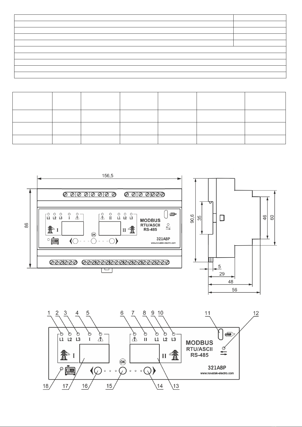
The overall dimensions of 321АВР are shown in Figure 1. The controls are shown in Figure 2. The connection
diagram is shown in Figure 3.
Fig. 1 –Overall dimensions of 321АВР
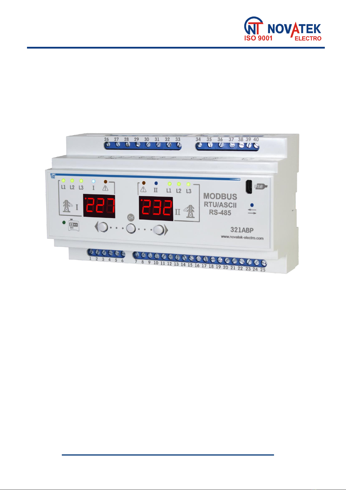
Fig. 2 –Controls and indication of 321ABP

~ 5 ~
PEF-321АВР NOVATEK-ELECTRO
The controls and indication:
1 –green LED «L1»lights if normal voltage is in phase
1 at input 1;
2 –green LED «L2»lights if normal voltage is in phase
2 at input 1;
3 –green LED «L3»lights if normal voltage is in phase
3 at input 1;
4 –blue LED «I»lights if the load has power supply
from input 1;
5 –red LED « » lights if there is at least one failure at
input 1;
6 –red LED « » lights if there is at least one failure at
input 2;
7 –blue LED «II»lights if the load has power supply
from input 2;
8 –green LED «L1»lights if normal voltage is in phase
1 at input 2;
9 –green LED «L2»lights if normal voltage is in
phase 2 at input 2;
10 –green LED «L3»lights if the normal voltage is in
phase 3 at input 2;
11 –connector for USB communication;
12 –blue LED « »blinks when transmitting data via
USB or RS-485, it does not light up if data transfer
is not used;
13 –input 2 displays phase and line voltage values,
input 2 network frequency and menu values;
14 –button « »;
15 –button «OK»;
16 –button « »;
17 –display of input 1 displays phase and line voltage
values, input 1 network frequency and menu.
18 –green LED « »lights if the generator is
connected to the load; blinks if time is running. It is
off when operating from the mains.
Functions of 321ABP terminals:
1 –input 1 control (normally open contact);
25 –RS-485-G;
2 –input 1 control (common contact);
26 –the first phase of input 1 to power the device;
3 –input 1 control 1 (normally closed contact);
27 –the second phase of input 1 to power the device;
4 –input 2 control (normally open contact);
28 –the third phase of input 1 to power the device;
5 –input 2 control (common contact);
6 –input 2 control (normally closed contact);
29 –neutral wire of input 1 to power the product;
30 –the first phase of input 2 to power the device or connect the
generator;
7,8,9,10,11 –not involved;
31 –the second phase of input 2 to power the device or connect
the generator;
12,13 –the state of voltage at input 1;
32 –the third phase of input 2 to power the device or connect
the generator;
14,15 –the state of voltage at input 2;
33 –neutral wire of input 2 to power the device or connect the
generator;
16,17 –the state of voltage on both inputs;
34 –the first phase of voltage measurement at the load;
18,19 –the state of generator operation;
35 –the second phase of voltage measurement at the load;
20 –generator control (normally open contact);
36 –the third phase of voltage measurement at the load;
21 –generator control (common contact);
37 –not involved;
22 –generator control (normally closed contact);
38 –external button to turn on the device from the battery;
23 –RS-485-A;
39 –“+” of power supply from the 12-V battery;
24 –RS-485-B;
40 –“-” of power supply from the 12-V battery.
4 OPERATION CONDITIONS
The product is designed for operation in the following conditions:
–Ambient temperature: from minus 35 to +55°C;
–Atmospheric pressure: from 84 to 106.7 kPa;
–Relative air humidity (at temperature of +25°C): 30 … 80%.
If the temperature of the device after transportation or storage differs from the ambient temperature at which it
is supposed to be operated, then before connecting to the mains keep the device under the operating conditions
within two hours (because of condensation may be on the device elements).
ATTENTION! The product is not intended for operation in the following conditions:
–Significant vibration and shocks;
–High humidity;
–Aggressive environment with content in the air of acids, alkalis, etc., as well as severe
contaminations (grease, oil, dust, etc.).
5 CONTENTS OF DELIVERY
The contents of delivery is shown in Table 4.
Table 4 - The contents of product delivery
Description
Quantity, pcs
321АВР
1
Coupling cable to connect a PC via USB
1
Operation Manual
1
Packing
1
~ 6 ~
NOVATEK-ELECTRO PEF-321АВР
6 USE AS INTENDED
6.1 Preparation for use
6.1.1 Preparation for connection::
-unpack the device and check the product for damage after transportation; in case of their detection,
contact the supplier or manufacturer;
-carefully study the Operation Manual (pay a special attention to the power supply circuits of the device);
-If you have any questions about the installation of the device, please contact the manufacturer over the
telephone number indicated at the end of the Operation Manual.
6.1.2 Connection of the device
ATTENTION! THE DEVICE IS NOT INTENDED FOR LOAD SWITCHIN OVER AT SHORT CASES.
THEREFORE, THE CIRCUIT OF INPUTS 1 AND 2 CONTROL CONTACTS MUST INCLUDE A CIRCUIT
BREAKER WITH A RATED CURRENT OF MORE THAN 5 A, CLASS "B".
ALL CONNECTIONS MUST BE PERFORMED WITH THE DEVICE BEING DEENERGIZED.
An error in installation work may result in damage of the device and instruments connected to it.
To ensure reliability of electrical connections, flexible (multi-wire) conductors should be used with insulation
for voltage of at least 450 V, the ends of which must be stripped of insulation by 5 ± 0.5 mm and crimped with
bushings. It is recommended to use a wire with a cross-section of at least 1 mm2. The fastening of the wires
should exclude mechanical damage, twisting and abrasion of wire insulation.
DO NOT LEAVE BARE SPOTS OF WIRE EXTENDING OUTSIDE THE TERMINAL.
For reliable contact, it is necessary to tighten the terminal block screws with the force specified in
Table 1.
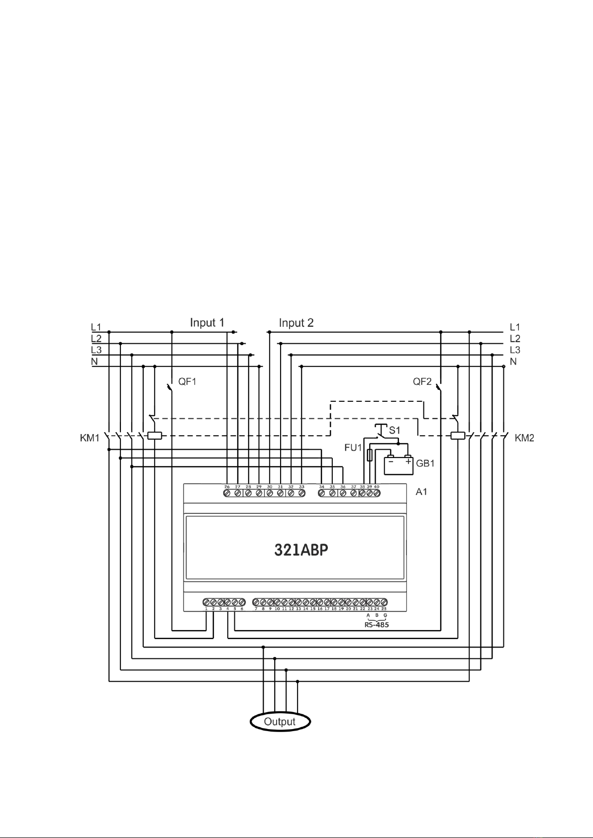
А1 –321АВР;
FU1 –0.5 A fuse;
GB1 –battery 12 V, 2 A·h;
KM1, KM2 –three-phase magnetic starters;
QF1, QF2 –circuit breakers;
S1 –normally open button without locking. Current of 0.5 A
at 12 V in the closed position.
Fig. 3 - Connection diagram of 321АВР
~ 7 ~
PEF-321АВР NOVATEK-ELECTRO
If the tightening torque decreases the connection site heats up, the terminal board may melt and the wire may
flame up. With an increase in the tightening torque, there may be breakage in the thread of the terminal block
screws or pinching in the connected wire.
To improve the operational properties of the product, it is recommended to install circuit breakers in
the 321АВР power supply circuit rated for current of 0.5 A.
The option of the 321ABP connection is shown in Figure 3.
If the neutral wires of various inputs are isolated, then contactors with four contact groups must be used. The
measuring circuits of various inputs inside the device are galvanically isolated from each other.
It is recommended for additional protection against simultaneous connection of two inputs, to switch on
additional groups of contacts on the contactors (normally closed) in the power supply circuit of the opposite
inputs (as shown in Fig, 3).
To ensure MODBUS communication in the absence of voltage at two inputs, it is recommended to connect a
12 V 2 A h battery to terminals 39 - 40.
Attention! When working with the generator, terminals 39 -40 must get supply from an external
battery.
6.2 Operation of the device
6.2.1 Modes of operation
321АВР supports 6 operating modes:
–two equivalent three-phase inputs;
–two three-phase inputs with priority input 1;
–two three-phase inputs with priority input 2;
–three-phase input 1 and a three-phase generator at input 2;
–work only with input 1;
–work only with input 2.
6.2.1.1 With equivalent inputs and with normal voltages at the both inputs, the device connects the load to
input 1 by contactor K1.
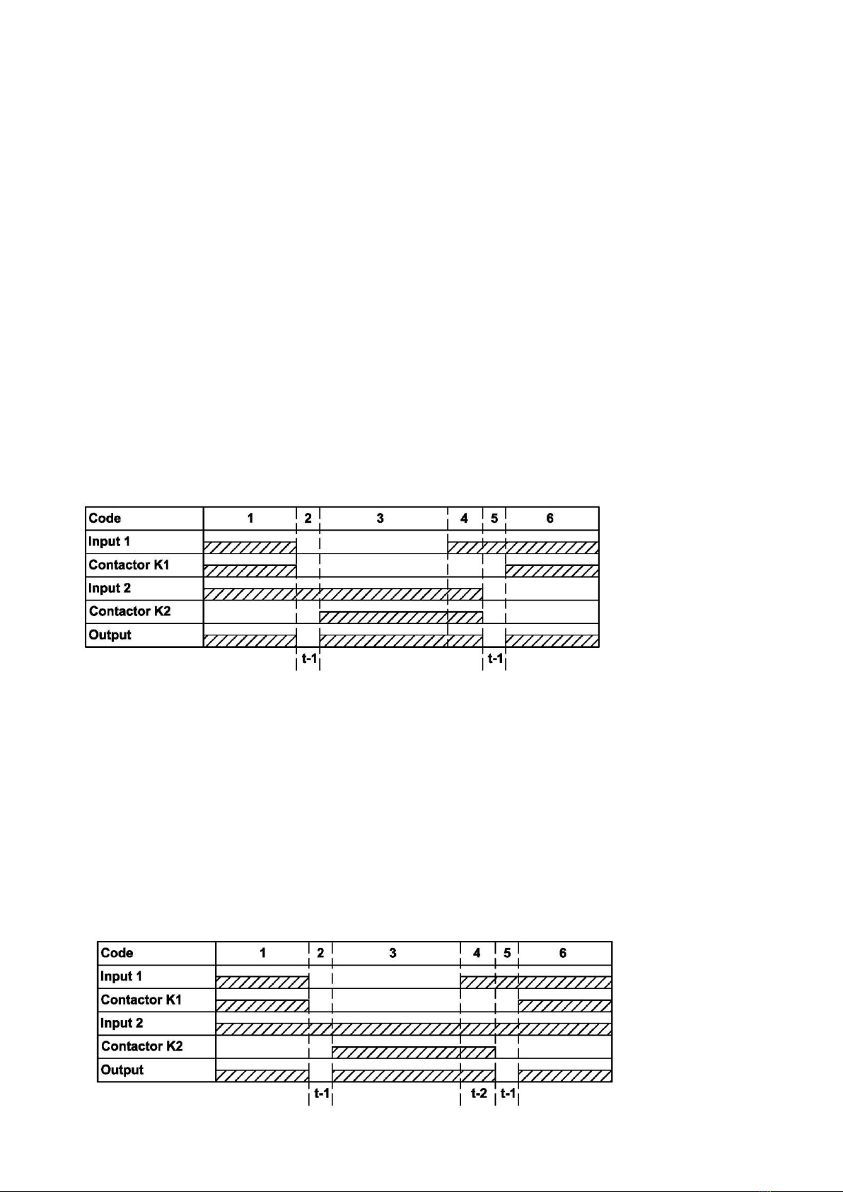
Fig. 4 –Diagram of
work with equivalent
entries
Figure 4 shows the diagrams of work with equivalent inputs. Detailed description of Figure 4:
1 –Normal voltages are present at inputs 1 and 2. The 321ABP connects the load to input 1 by contactor
K1.
2 –At input 1, the voltage went beyond the limits set by the user (a failure occurred). The device
disconnects the load from input 1 by contactor K1 and counts the transition time to another input
(«», table 5).
3 –After completion of the countdown «», the device connects the load to input 2 by the contactor K2.
4 –Some voltage appeared at input 1.
5 –At input 2, the voltage went beyond the limits set by the user (a failure occurred). The device
disconnects the load from input 2 by the contactor K2 and counts the transition time to another input
(«», table 5).
6 –After completion of the «»countdown, the device connects the load to input 1 by the contactor K1.
6.2.1.2 Figure 5 shows the diagrams of work with priority input 1 (Work with priority input 2 is similar).
Fig. 5 –Diagrams of work
with priority input 1
~ 8 ~
NOVATEK-ELECTRO PEF-321АВР
Detailed description of Figure 5:
1 –normal voltages are present at inputs 1, 2. Device 321АВР connected the load to input 1 by contactor
K1.
2 –at input 1, the voltage went beyond the limits set by the user (a failure occurred). The device
disconnects the load from input 1 by contactor K1 and counts the transition time to input 2 («»,
table 5).
3 –after the completion of the «», countdown, the device connects the load to input 2 by contactor K2.
4 –Some voltage appeared at input 1. Device 321АВР counts the time of return to the priority input («»,
table 5).
5 –the device disconnects the load from input 2 by contactor K2 and counts the transition time to another
input («», table 5).
6 –the device connects the load to input 1 by contactor K1.
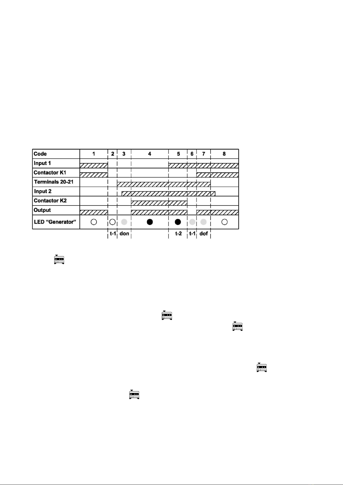
6.2.1.3 To work with a three-phase generator, it must be connected to input 2 (terminals 30–33) and select
the appropriate mode of operation with a three-phase generator –«» («», table 5). The trigger signal for the
generator is generated by the device in the event that a failure occurs at input 1. The start and stop signal of the
generator is shaped by the internal relay of the device, the contacts of which go to terminals 20, 21, 22 (20 - 21 -
normally open contact, 21 - 22 normally closed contact).
Fig. 6 –Diagrams of works
with a generator at input 2
A detailed description of work with a generator, in accordance with Fig. 6:
1 –Input 1 has a normal voltage. Device 321 АВР connected the load to input 1 by Contactor K1. The LED
«»does not light.
2 –At input 1, voltage went beyond the limits set by the user (a failure occurred). The device disconnects
the load from input 1 by contactor K1 and counts the transition time to the secondary input («»,
table 5).
3 –After completion of the «», 321АВР time countdown, device 321АВР closes terminals 20 - 21 (sends
a signal to start the generator). The time for starting and warming up of the generator is counted
(«», table 5). A test check is made for absence of voltage at the load (terminals 34 - 36) and for
absence of failures at input 2. The LED «» flashes.
4 –The device connects the load to input 2 by contactor K2. The LED «»lights up.
5 –Some voltage appeared at input 1. The device counts the time of return to the priority input («»,
table 5).
6 –After completion of the «» countdown, the device disconnects the load from input 2 by the contactor
K2. A test check is made for absence of voltage at the load (terminals 34 36) and absence of failures at
input 1. The device will count the time «»and «» (table 5). The LED «»flashes.
7 –After completion of time «»countdown, the device will connect the load to input 1 by contactor K1.
8 –After completion of the «»countdown, the device will open terminals 20 - 21 (it sends a signal to turn
off the generator). The LED «» goes off.
6.2.1.4 Battery connection
The battery is connected to terminals 39 and 40, as shown in Figure 3.
The battery is charged in the buffer mode with current of not more than 60 mA. It is not recommended to use
a battery with a capacity of more than 2 Ah because of the low charge current.
Attention! Devices connected in parallel to the battery affect its charge.
If there is voltage of 100 V, at least at one of the phases of any input, the device is powered by this voltage.
Otherwise, 321 АВР is powered by a battery with current of not more than 100 mA. If the battery is discharged to
11.5 V, then 321АВР will disconnect the battery from the circuit and it will stop working. The next time the device

~ 9 ~
PEF-321АВР NOVATEK-ELECTRO
will be energized when voltage appears at one of the inputs or after replacing the battery with a charged one,
followed by a short pressing of an external button connected to the terminals (38 - 39).
If voltage appeared at any input when supply is from the battery, then after 12 s device 321 АВР will be
switched over to the mains supply, and the battery will be charging.
The measured battery voltage is available for reading at MODBUS and is converted to an integer value
(multiplied by 100), address 25. Also, the flag of battery connection to the terminals (38 - 39) is transmitted to
address 43, bit 4.
6.2.2 Menu setting and viewing
6.2.2.1 Menu settings
To enter the menu, press and hold the «OK» button for 3 s. Display at input 1 will show «», and at
display of input 2 there will be «». Enter the password in accordance with clause 6.2.2.2. The factory default
password is «». If the «»value (table 5) is set to «»(password is not set), then after holding the «OK»
button for 3 seconds, you will immediately enter the menu.
To view and change menu values it is necessary:
–after entering the menu to select the desired menu item by using «» or «» buttons, it will be displayed
on the input 1 display, and its value - on the input 2 display;
–to change the value, press the «OK»button, thereby the value on the input 2 display will flash;
–change the flashing value with the buttons «» and « »;
–to save the data, briefly press the «OK». The value on the input 2 display stops flashing, you can
proceed to view and configure other menu items.
In order to exit the menu, press and hold the «OK»button for 3 s. If no button is pressed within 30 s, the
menu will exit automatically.
Table 5 - Menu
Menu
Value
Name
Description
Address
Basic items
Mode of operation
«» –equivalent inputs;
«» –priority input 1;
«» –priority input 2;
«» –work with a 3-phase generator;
«4» –work only with input 1;
«5» –work only with input 2.
100
Setting of the password
Described in clause 6.2.2.2
101
Voltage output
«» –permanent display of one of the
voltages;
«» –voltage display in turn, with interval of 5 s
102
Ratio of the minimum time of work
after load activation
Within 0 to 5 activations. If «0»is selected, this
parameter is disabled
103
Full phase shutdown
«»–full phase shutdown –a norm;
«» –full phase shutdown –a failure
104
Reset to factory settings
If «1» is written, there will be resetting of all
parameters of the menu
105
Voltages
Type of voltage measurement
«» –phase voltages;
«» –line voltages
106
Minimum phase voltage at input 1
From 140 to 230 V with interval of 5 V
107
Minimum phase voltage at input 2
108
¯
Maximum phase voltage at input 1
From 235 to 260 V with interval of 5 V
109
¯
Maximum phase voltage at input 2
110
Minimum line voltage at input 1
From 240 to 395 V with interval of 5 V
111
Minimum line voltage at input 2
112
¯
Maximum line voltage at input 1
From 405 to 450 V with interval of 5 V
113
¯
Maximum line voltage at input 2
114
Voltage imbalance at input 1
From 15 to 140 V with interval of 5 V
115
Voltage imbalance at input 2
From 15 to 140 V with interval of 5 V
116
Response time in case of failure
.
Minimum voltage
From 0.0 to 10.0 seconds with interval of 0.5 s.
If «0.0»value is set, this item of the check is
not used
117

~ 10 ~
NOVATEK-ELECTRO PEF-321АВР
Table 5 (continued)
¯
.
Maximum voltage
From 0.0 to 3.0 seconds with interval of 5 s. If
«0.0»value is set, this item of the check is not
used.
118
.
Voltage imbalance
119
.
Phase sequence
120
.
Phase breakage
121
.
Phase sticking
122
.
Contactor sticking
From 0.5 to 3.0 seconds with interval of 0.5 s
123
Minimum time of operation after
load connection
From 5 to 600 s
124
Time of switching over
.
Switching over to another input
From 0.5 to 900.0 s
125
.
Reset to the priority input
126
Work with a generator
Time of idle work of the generator
before its start
From 5 to 900 s
129
Time of idle work of the generator
before its switching off
130
Generator de-energizing in case of
failure
«» –enabled;
«» –forbidden
131
Parameters of the series connected interface (RS-485/ USB)
Enabling to change data
throughout the network
«» –enabled;
«» –forbidden
132
Data transfer interface
«» –communication via RS-485;
«» –communication via USB;
«» –communication is forbidden
133
Type of communication protocol
0 –«ASCII»; 1 – «RTU» –MODBUS modes
134
Parity check
«» –parity check is off;
«» –even parity check;
«» –odd parity check
135
Number of stop bits
«»or «».
136
Transfer rate
«» –transfer rate –2400 baud;
«» –transfer rate –4800 baud;
«» –transfer rate –9600 baud;
«» –transfer rate –14,400 baud;
«» –transfer rate –19,200 baud
137
Number of the device in the
network
From 1 to 247 with interval 1
138
Frequency
Frequency protection
«» –no frequency protection;
«» –protection on both inputs;
«» –protection of input 1;
«» –protection of input 2
139
Response time for frequency
control
From 5 to 20 seconds with interval of 5 s
140
¯
.
Upper limit of frequency at input 1
From 50.10 to 65.00 Hz with interval of 0.10 Hz
141
_
.
Lower limit of frequency at input 1
From 45.00 to 49.90 Hz with interval of 0.10 Hz
142
.
Upper hysteresis of frequency at
input 1
From 0.10 to 2.00 Hz with interval of 0.10 Hz
143
.
Lower hysteresis of frequency at
input 1
144
¯
.
Upper limit of frequency at input 2
From 50.10 to 65.00 Hz with interval of 0.10 Hz
145
_
.
Lower limit of frequency at input 2
From 45.00 to 49.90 Hz with interval of 0.10 Hz
146
.
Upper hysteresis of frequency at
input 2
From 0.10 to 2.00 Hz with interval of 0.10 Hz
147
.
Lower hysteresis of frequency at
input 2
148
~ 11 ~
PEF-321АВР NOVATEK-ELECTRO
6.2.2.2 Password setting
Input 1 will display «»and input 2 will display –«», with the most significant digit flashing. Use the
« »and « »buttons to alternately a flashing value of the high, middle and low order bits, while preserving the
value of each bit by briefly pressing the «OK»button. If you set the password value to «», then it will not be
requested.
6.2.2.3 Displaying of network voltage and frequency values
Depending on the «»setting (Table 5), the values can be displayed in two modes:
1) If «» = «», then during 321АВР operation, both displays will read values of phase or linear voltages,
the network frequency value at inputs 1 and 2.
In this mode, using the « »and « »you can switch the display of voltage values and network frequency in
accordance with Table 6.
2) If «» = «», then during 321АВР operation, both displays will alternately read with an interval of 5 s
values of phase or linear voltages at inputs 1 and 2 depending on the parameter «». If «» = «0», then
phase voltages will be output alternately, and if «» = «1», then linear voltages will be output. However, the
frequency value is not displayed.
Using the « »and « »buttons, you can switch the display of network voltage and frequency in accordance
with Table 6, but 15 seconds after the last pressing of the «» and «» buttons, only phase or only linear
voltages will be displayed again, as described above.
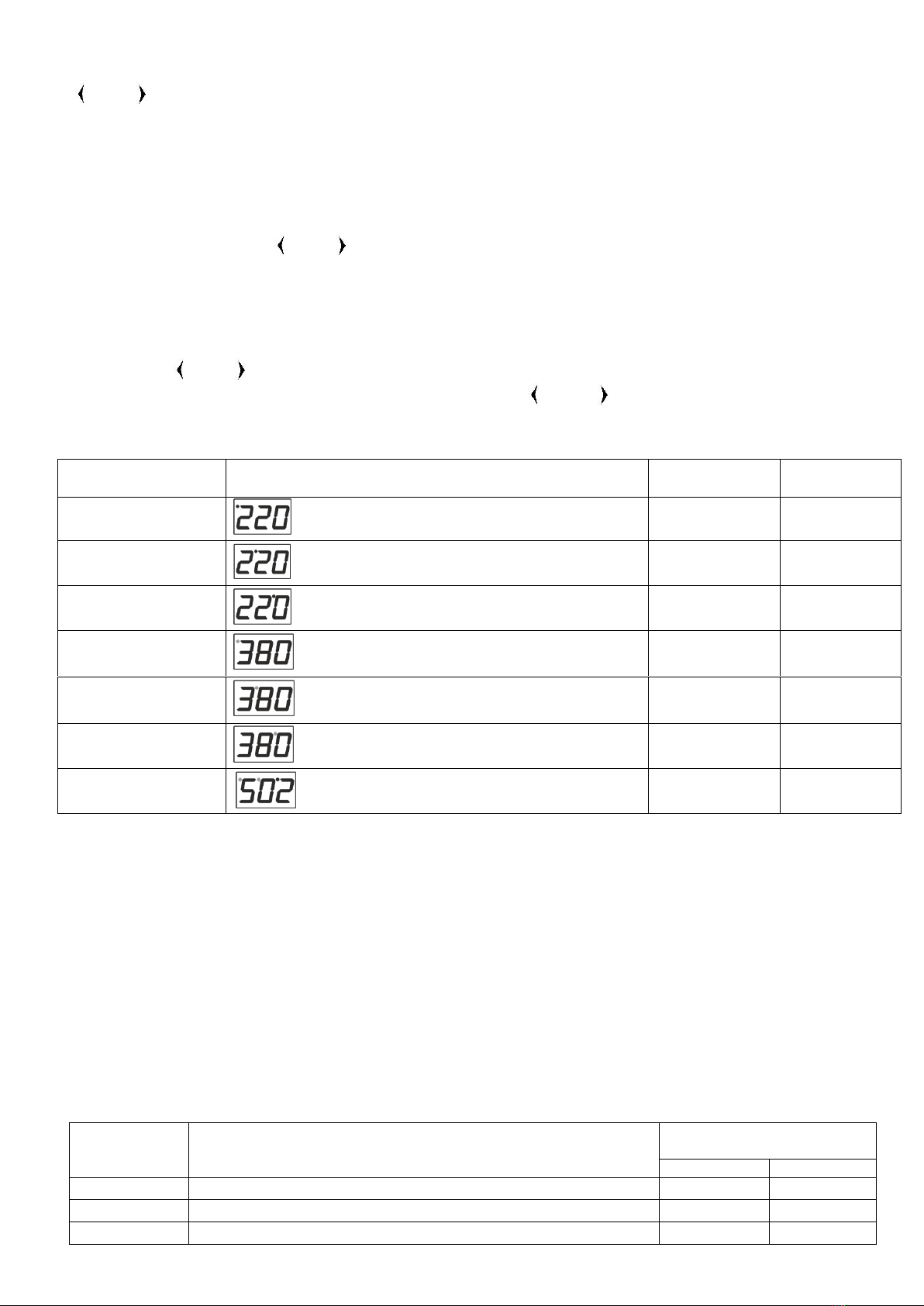
Table 6 - Indication of phase and linear voltage values
Type of voltage
Designation of the type of voltage
Address of
input 1
Address of
input 2
Phase voltage of
phase 1
High order dot is lighting
11
12
Phase voltage of
phase 2
Mid-order dot is lighting
13
14
Phase voltage of
phase 3
Low-order dot is lighting
15
16
Linear voltage of
phases 1, 2
High-order dot is flashing
17
18
Linear voltage of
phases 2, 3
Mid-order dot is flashing
19
20
Linear voltage of
phases 1,3
Low-order dot is flashing
21
22
Frequency
Dots in the high and mid-order are flashing
and a dot in the low order if lighting
23
24
Flags of voltage presence at the load are transmitted via MODBUS with addresses 44.1 (phase 1), 44.2
(phase 2), 44.3 (phase 3). If the corresponding bit is «1» there is voltage in the phase, if «0»- there is no voltage
in the phase.
6.2.2.4 Indication of failures
Failures are indicated on the display by three characters. The first two are «»,and the third one is different
for each failure (according to Table 7). If one of the indicated failures occurs, the input 1 or 2 display (depending
on the input at which the failure occurred) will periodically display a code for this failure. The EEPROM failure
() is displayed on two displays at once and the device will be blocked.
In case of a failure as contactor sticking (), the failure can be displayed both on one of the displays and
on the both of them at once (the device is blocked until the power is reset). In the first case (indication on
one of the displays), device 321АВР determined that sticking occurred on the corresponding input (input 1 - the
left display, input 2 –the right display) when the contactor opens. In the second case (indication on the both
displays), it was not possible to determine on which contactor sticking had occurred.
Table 7 –Types of failures
Code of
failure
Explanation
Address of the register
Bit №
Input 1
Input 2
Contactor sticking when switching on
41:0
41:1
Contactor sticking when switching off
41:2
41:3
Voltage imbalance
41:4
41:5

~ 12 ~
NOVATEK-ELECTRO PEF-321АВР
Table 7 (continued)
Failure in phase sequence
41:6
41:7
Phase breakage
41:8
41:9
Phase sticking
41:10
41:11
Failure of generator start
---
41:13
Failure in generator stoppage
---
41:15
42:0
Failure in automatic re-closure ratio
42:1
42:2
Failure in frequency
42:3
42:4
Voltage goes beyond the lower limit set by the User
42:5
42:6
Voltage goes beyond the higher limit set by the User
42:7
42:8
If a failure occurs at input 1, then the LED « » of input 1 will light up,if at input 2, then the LED « » of
input 2 will light up.
6.2.2.5 External indication
The 321АВР has 4 outputs to the terminal for connecting an external indication. Table 8 shows the
connections for external displays.
Table 8 - External Indication
Terminals
Type of
thermocouple
Name
Explanation of operation of the indicator
connected to respective terminals in series
with the source of power supply
Max. duration of
allowable AC/DC
voltage, V
12 –13
Triacoutput
photocoupler
The state of
voltage at input
1
Lighting up –voltage is within the norm;
Is flashing –voltage is beyond the limits set
by the User;
Is not lighting –no voltage
400 AC
14 –15
Triacoutput
photocoupler
The state of
voltage at input
2
Lighting up –voltage is within the norm;
Is flashing –voltage is beyond the limits set
by the User;
Is not lighting –no voltage
400 AC
16 –17
Optotransistor
Availability of
the battery
Is not lighting –the battery is disconnected;
Is lighting –the battery is connected
280 AC /
400 DC
18 –19
Optotransistor
The state of
generator
operation
Duplicates LED " "
6.2.3 MODBUS parameters
The parameters available for reading upon the MODBUS protocol are shown in Table 9. The parameter sets
available upon the MODBUS protocol are shown in Table 10.
Table 9 - Parameters accessible for reading upon MODBUS protocol
Parameter
Address
Type of the device
Code, defining the device of MODBUS for a manufacturer (25 321АВР)
0
Firmware version
Firmware version for the built-in software (firmware version, for example «2.3»,
is transmitted upon MODBUS as «0x0203»)
1
Time account for switching over to another input
26
Time account for return to the foreground input
27
Time account for waiting for generator start
29
Time account for generator idle work before switching off
30
The state of input 1 relay
1 –normally-open contacts are closed;
0 –normally-open contacts are open
43:0
The state of input 2 relay
43:1
The state of the generator relay
43:2
The state of the battery relay
43:3
Availability of voltage at the load, phase 1
1 –voltage is present at the load;
0 –no voltage at the load
44:1
Availability of voltage at the load, phase 2
44:2
Availability of voltage at the load, phase 3
44:3
Table 10 –Parameters available upon the MODBUS protocol
Access
Addresses
Reading and writing
100 –250
Only reading
0 –99
~ 13 ~
PEF-321АВР NOVATEK-ELECTRO
6.3 Work with interface RS (EIA/TIA)-485 upon the MODBUS protocol
6.3.1 General
321АВР allows to perform data exchange with external devices via the serial RS (EIA/TIA)-485 interface
using the MODBUS protocol with a limited set of commands (the list of supported functions is shown in Table 12.
Table 12 - List of supported functions
Function (hex)
Purpose
Note
0x03
Reading of one or several registers
Maximum 50
0x06
Writing of one value to the register
----
When designing a network, the principle of the master-slave arrangement is used, where device 321АВР acts
as a slave. A network can have only one master unit and several slave units. The master unit is a personal
computer or a programmable logic controller. With this setting up, the initiator of the exchange cycles can only be
the master unit.
Requests of the master unit are individual (addressed to a specific device). The 321АВР device performs
transmission, responding to individual requests of the master unit.
If errors are detected in receiving requests, or if it is impossible to execute the received command, 321АВР
generates an error message as a response (Table 13).
In 321ABP, all values with a dot are converted to integers. Therefore, when processing data, it is necessary to
apply additional mathematical operations.
When reading a value with a dot (for example, 1.000) 321АВР will return an integer value of 1000, in order to
convert the read value to the correct format, it is necessary to divide by.
Before writing a value with a dot (for example, 1.000) you must reduce it to an integer value by multiplying the
value by 1000, then write the value to 321АВР.
The coefficient of reduction to an integer value is determined by a number of decimal places (1,0 –10; 1,00 –
100; 1,000 - 1000).
Table 13 - Error codes for the MODBUS protocol
Error
code
Name
Error description
01
ILLEGAL FUNCTION
The accepted function code cannot be processed
02
ILLEGAL DATA ADDRESS
The data address specified in the request is not available
03
ILLEGAL DATA VALUE
The value contained in the query data field is not a valid value
04
SERВER DEVICE FAILURE
An unrecoverable error occurred while the slave device was
attempting to perform the requested action
05
ACKNOWLEDGE
The slave device has accepted the request and is processing it,
but this is time consuming
06
SERВER DEVICE BUСY
The slave device is busy processing the command. The master
unit should retry the message later when the slave is free
07
NEGATIVE_ACKNOWLEDGE
The slave device cannot execute the software function specified in
the request
08
MEMORY PARITY ERROR
When reading the extended memory, the slave device detected a
parity error
6.3.2 Message Formats
The exchange protocol has clearly defined message formats. Compliance with the formats ensures the
correctness and stability of the network.
The data in the message is transmitted in high byte forward.
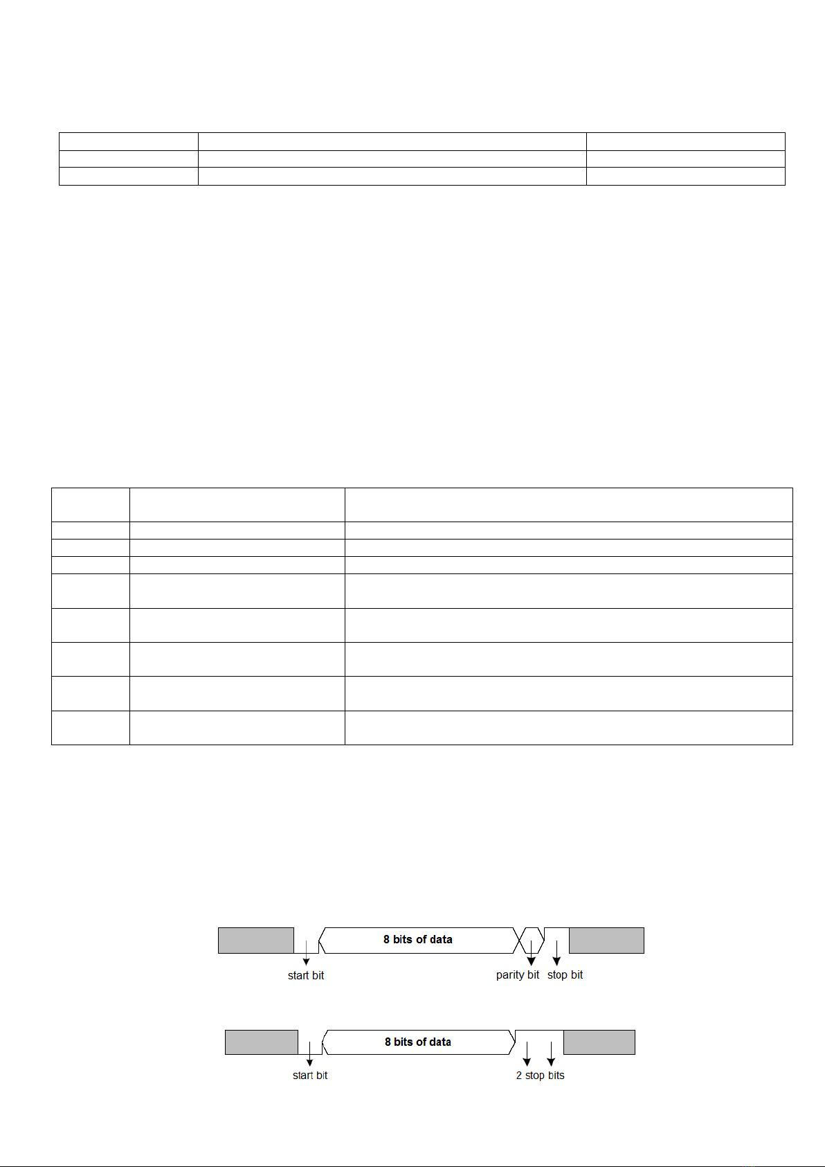
6.3.2.1 Byte format
321АВР is configured to work with one of two data byte formats: with parity control (Figure 7) and without
parity control (Figure 8). In the mode of operation with parity control, the type of control is also indicated: parity
(Even) or oddness (Odd). The transmission of data bits is performed by the least significant bits forward.
By default (during manufacture), the device is configured to operate without parity and with two stop bits.
Fig. 7 –Byte format with a parity control
Fig. 8 - Byte format without parity control (2 stop bits)

~ 14 ~
NOVATEK-ELECTRO PEF-321АВР
Bytes are transmitted at speed of 2400, 4800, 9600, 14400 and 19200 bps. By default, during manufacture,
the device is configured to operate at a speed of 9600 bps.
Note - for MODBUS RTU mode, 8 data bits are transmitted, and for MODBUS ASCII mode, - 7 data bits are
transmitted.
6.3.2.2 Frame format
In the MODBUS RTU mode, the start and end of the frame are controlled using silence intervals of at least
3.5 bytes transmission time. The frame should be transmitted as a continuous stream of bytes. The correctness
of the frame acceptance is further controlled by checking the CRC checksum.
The address field takes up one byte. Addresses of the slave devices are in the range from 1 to 247.
Figure 9 shows the RTU frame format.
Silence interval
>3.5 bytes
Address
Function code
Data
CRC checksum
Silence interval
>3.5 bytes
1 byte
1 byte
Up to 50 bytes
2 bytes
Fig. 9 - RTU frame format
In the MODBUS ASCII mode, the start and end of the frame are controlled using special characters (symbol
(„:‟ 0x3A) –to start the frame; characters („CRLF‟ 0x0D0x0A) –to end the frame). The frame should be
transmitted as a continuous stream of bytes. The correctness of the frame acceptance is further controlled by
checking the LRC checksum.
The address field takes up two bytes. Addresses of the slave devices are in the range from 1 to 247.
Figure 10 shows the ASCII frame format.
:
1 byte
Address
Function code
Data
CRC checksum
CRLF
2 bytes
2 bytes
2 bytes
Up to 504 bytes
2 bytes
Fig. 10 - ASCII frame format
Note - in the MODBUS ASCII mode, each byte of data is encoded with two bytes of ASCII code (for example:
1 byte of data 0x25 is encoded with two bytes of ASCII code 0x32 and 0x35).
6.3.3 Generation and verification of a checksum
The transmitting device generates a checksum for all bytes of the transmitted message. 321АВР similarly
generates a checksum for all bytes of the received message and compares it with the checksum received from
the transmitting device. If the generated checksum does not match the accepted one, an error message is
generated.
6.3.3.1 CRC checksum generation
The checksum in the message is transmitted in the lower byte forward; it is a cyclic check code based on the
irreducible polynomial 0xA001.
The subroutine for generating CRC checksum is in C language:
1: uint16_t GenerateCRC(uint8_t *pСendRecvBuf, uint16_t uCount)
2: {
3: conсuint16_t Polynom = 0xA001;
4: uint16_t crc = 0xFFFF;
5: uint16_t i;
6: uint8_t byte;
7: for(i=0; i<(uCount-2); i++){
8: crc = crc ^ pСendRecvBuf[i];
9: for(byte=0; byte<8; byte++){
10: if((crc& 0x0001) == 0){
11: crc = crc>> 1;
12: }elсe{
13: crc = crc>> 1;
14: crc = crc ^ Polynom;
15: }
16: }
17: }
18: returncrc;
19: }
6.3.3.2 LRC checksum generation
The checksum in the message is transmitted in high byte forward, which is a longitudinal redundancy check.

~ 15 ~
PEF-321АВР NOVATEK-ELECTRO
The subroutine for generating LRC checksum is in C language:
1: uint8_t GenerateLRC(uint8_t *pСendRecvBuf, uint16_t uCount)
2: {
3: uint8_t lrc = 0x00;
4: uint16_t i;
5: for(i=0; i<(uCount-1); i++){
6: lrc = (lrc + pСendRecvbuf[i]) & 0xFF;
7: }
8: lrc = ((lrc ^ 0xFF) + 2) & 0xFF;
9: returnlrc;
10: }
6.3.4 Set of instructions
6.3.4.1 Function 0x03 - read operation of a group of registers
The 0x03 function reads the contents of 321ABP registers. The master‟s request contains the address of the
initial register, as well as the number of words to read.
Answerback of 321АВР contains the number of bytes returned and the requested data. The number of
registers returned is limited to 50. If the number of registers in the request exceeds 50, the response is not split
into frames.
An example of a request and response in the MODBUS RTU is shown in Figure 11.
Request
Address
Function
In. address
HB
In. address
LB
Number of words
HB
Number of words
LB
CRC LB
CTC HB
01h
03h
00h
A0h
00h
02h
C4h
29h
Answerback
Address
Function
Number of
bytes
HW HB
data
HW LB
data
LW HB
data
LW LB
data
CRC LB
CTC HB
01h
03h
04h
44h
7Ah
00h
00h
CFh
1Ah
Fig. 11 - Example of request and response of function 0x03 - reading a group of registers
6.3.4.2 Function 0x06 - register entry
Function 0x06 provides writing to one 321ABP register. The master‟s request contains the address of the
register and data for entering.
The answer of the device coincides with the request of the master unit and contains the address of the
register and the established data. An example of a request and answer in the MODBUS RTU mode is shown in
Figure 12.
Request –register 00A0h = 1000 (INT)
Address
Function
In. address
HB
In. address
LB
HB
data
LB
data
CRC LB
CTC HB
01h
06h
00h
A0h
03h
E8h
89h
56h
Answerback
Address
Function
In. address
HB
In. address
LB
HB
data
LB
data
CRC LB
CTC HB
01h
06h
00h
A0h
03h
E8h
89h
56h
Fig. 12 - Example of request and answer of function 0x06 - register setting
7 MAINTENANCE
7.1 Safety precautions
THE TERMINALS AND THE DEVICE INTERNAL ELEMENTS CONTAINS POTENTIALLY LETHAL
VOLTAGE.
DURING MAINTENANCE IT IS NECESSARY TO DISABLE THE DEVICE AND CONNECTED
DEVICES FROM THE MAINS.
7.2 Maintenance of the device must be performed by the skilled professionals.
7.3 Recommended frequency of maintenance is every six months.
7.4 Maintenance Procedure:
1) Check the connection reliability of the wires, if necessary, clamp with the force specified in Table 1;
2) Visually check the integrity of the housing, in case of detection of cracks and damages take the device out
of service and send for repair;
3) If necessary, wipe the front panel and the housing of the device with cloth.
Do not use abrasives and solvents for cleaning.

~ 16 ~
NOVATEK-ELECTRO PEF-321АВР
8 SERVICE LIFE AND MANUFACTURER WARRANTY
8.1 The lifetime of the device is 10 years. Upon expiration of the service life, contact the manufacturer.
8.2 Shelf life is 3 years.
8.3 Warranty period of the device operation is 5 years from the date of sale.
During the warranty period of operation (in the case of failure of the device) the manufacturer is responsible
for free repair of the device.
ATTENTION! IF THE DEVICE HAS BEEN OPERATED IN VIOLATION OF THE REQUIREMENTS OF THIS
OPERATION MANUAL, BUYER WILL FORFEIT THE RIGHT TO WARRANTY SERVICE.
8.4 Warranty service is performed at the place of purchase or by the manufacturer of the device.
8.5 Post-warranty service of the device is performed by the manufacturer at current rates.
8.6 Before sending for repair, the device should be packed in the original or other packing excluding
mechanical damage.
You are kindly requested, in case of the device return and transfer it to the warranty (post-warranty) service
please indicate detailed reason for the return in the field of the claims data.
9 TRANSPORTATION AND STORAGE
The device in the original package is permitted to be transported and stored at the temperature from minus 45
to +60 °C and relative humidity of no more than 80 %.
10 ACCEPTANCE CERTIFICATE
PEF-321АВР has been manufactured and accepted in accordance with the requirements of valid technical
documentation and classified as fit for operation.
Head of QCD Date of manufacture
_____________ _____________
Seal
11 CLAIMS DATA
_____________________________________________________________________________________
_____________________________________________________________________________________
_____________________________________________________________________________________
_____________________________________________________________________________________
_____________________________________________________________________________________
_____________________________________________________________________________________
_____________________________________________________________________________________
_____________________________________________________________________________________
The Company is grateful to you for the information about the quality of the device and suggestions for its operation.
For all questions, please contact the manufacturer:
NOVATEK-ELECTRO Ltd,
59 Admiral Lazarev Str.;
Odessa 65007, Ukraine.
Tel.: (048)738-00-28;
Tel./fax: (0482) 34-36-73;
http://novatek-electro.com
Date of sale: __________ VN190618
Table of contents
Popular Control Unit manuals by other brands


DMP Electronics
DMP Electronics ITI 738I Installation and programming guide

Danfoss
Danfoss VLT AutomationDrive FC 360 installation instructions

Kemo
Kemo M028N Connection manual

MKS
MKS Granville-Phillips Series 275 instruction manual

Ebyte
Ebyte E19-433M20S2 user manual

RF SOLUTIONS
RF SOLUTIONS PB-03F user manual