NOAQ Boxwall BW102 User manual

User instructions
NOAQ Boxwall BW102
For instructions in other languages, see www.noaq.com
NOAQ BW102 1.0 201201
A NOAQ Boxwall is a mobile self-anchoring flood barrier. The NOAQ Boxwall BW102 creates
a dam for water up to a height of 100 cm. The boxwall is so light that it can quickly be set up
to protect buildings and other property against water damage, and also to keep roads open.
A boxwall is designed for use on an even surface, such as a paved street, a concrete floor
or a lawn.
A boxwall consists of sections (boxes) that are linked together by means of a simple manual
operation. No tools are needed.
The NOAQ Boxwall is also available in a lower model, called BW52, with a damming ability
of 50 cm.
NOAQ BW102 1.0 201201
2 (8)
Each box consists of a damming part (the rear wall), an anchoring part (the horizontal section
that rests on the ground) and a sealing part (the front edge of the horizontal section). Sealing
strips of cellular plastic are fitted under the front and side edges. Each box is also fitted with
three cellular rubber soles to create a good grip on the road.
A boxwall is built up by snapping boxes one at a time onto the previous one. The easiest
way is to work from left to right (viewed from the dry side). You should avoid working from
two directions, as it is difficult to make the two wall sections meet at exactly the same point.
As with all mobile flood barriers you need to count on a certain leakage. This can be minimized
by covering the barrier with a plastic liner. But water is also leaking through the ground under
the barrier. Water may also come to the protected area as rain and through brooks which have
been cut off by the barrier itself. Therefore one or more pumps must always be put on the
intended dry side of the barrier.
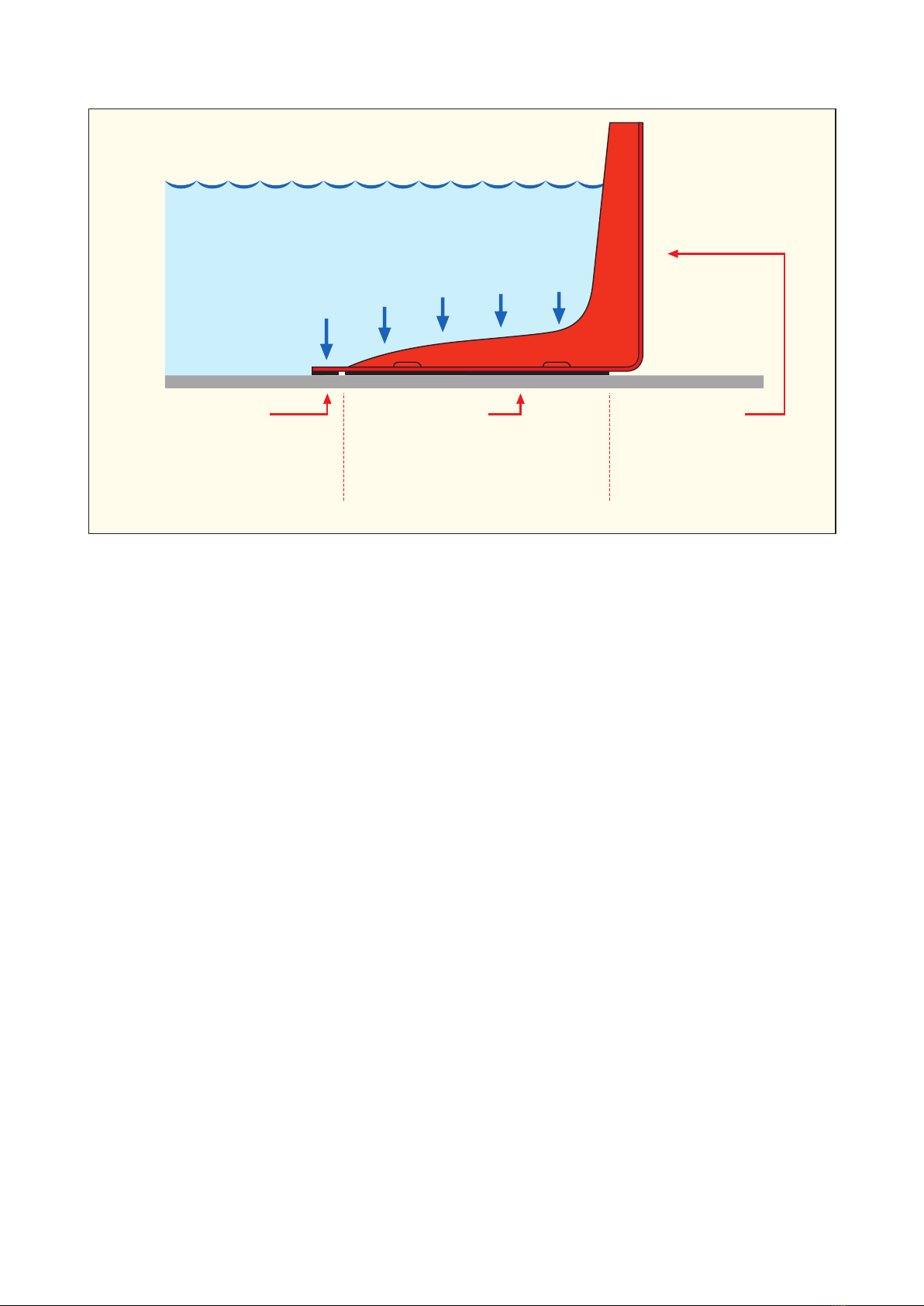
Sealing part
Beneath the front edge of
the boxwall is a sealing strip
made of cellular rubber. This
keeps the leakage of water
at the bottom to a minimum.
Anchoring part
The anchoring force is proportional to
the difference in water pressure between
the upper and lower side of the boxwall.
A system of drainage channels on the
lower side diverts the leaking water, so
that no counter pressure arises
Damming part
The rear wall dams the flood
water. The water’s pressure
is absorbed by a three large
bulges, which also act as
drainage channels.
This is how a NOAQ Boxwall works
The base section of the boxwall is pressed firmly against
the ground by the weight of the flood water. There are
three cellular rubber soles on the underside to provide
a reliable grip on the road.

3 (8)
NOAQ Boxwall BW102 together with the BW52
Follow these instructions:
1. Inspect the area where the boxwall is to be constructed
The boxwall has been specially designed for firm, even surfaces such as asphalt, concrete,
lawns etc. It is therefore ideal for setting up on streets and paths, across car parks, in industri-
al areas, around shopping malls, in harbours and at airports. It must not be used on surfaces
that are very uneven or on ground that is prone to erosion. Inclinations of the ground of up to
1:10 is no problem, but abrupt transitions from a surface with one inclination to an other need
to be done perpendicularly. Holes or bumps should be avoided. The boxes are 992 mm long
but overlap one another, which means each box adds 900 mm to the total barrier length. A box-
wall requires a free width of 1,200 mm.
Loose sand and gravel must be brushed away from where the wall is to be erected. The
soles attached beneath each box have just as good a grip as the rubber soles on your shoes.
If there is sand on the road you run the risk of slipping, and the same applies for the boxwall.
The coupling between the individual boxes has a built-in flexibility of +/-2°, which means a
boxwall can be drawn in curves. The curv radius then becomes 26 meters.
The boxwall can be placed on land that is already flooded, but if the ground surface is difficult
to see through the water, you must take particular care to make sure that the boxes are not
placed on uneven surfaces, on the wrong side of surface water drains, etc.
The boxes are easy to handle and move, and you can also adjust the setting of a constructed
boxwall as long as the water has not started to press firmly against the base. But you must
avoid dragging the boxes on the ground, as the sealing strips on the underside are vulnerable
to wear and may become damaged.
NOAQ BW102 1.0 201201

2. Lay out the boxes and connect them one by one
Start from the left (seen from the dry side) and connect the boxes one at a time to the previous
one. The boxes have a coupling mechanism (at the front) and a locking mechanism (at the
top). Tip the box slightly forwards and connect it with the previous box by inserting the protruding
”tongue” (on the far left) beneath the ”bridge” (on the right-hand side of the previous box).
Now lean the box a little to the side, press down its rear edge and insert the pin of the locking
mechanism into the groove in the previous box. Use your foot to hold up the right side of the
box to be able to use both hands for the coupling maneuver. Turn the box so that the pin ends
up in the middle of the groove. This is the normal position. However, the locking mechanism
has a certain flexibility allowing the boxes to be turned +/-2° against one another.
To help the sealing strip underneath create a tight seal against an uneven surface, you can
place a weight on the front edge of each box, for example a stone or a sandbag. It can also
be necessary to ballast the boxes in this way if there is a strong wind, before the water arrives.
The boxwall is not very susceptible to winds coming from the front, but winds from behind
will try to lift it.
Also when deploying a boxwall in deep water the boxes need to be ballasted from start to
prevent them from floating. A difference in levels between the water in front of the boxwall
and behind it is necessary to achieve the pressure difference that keeps the barrier in place.
If you want to improve the seal, you can cover the boxwall and its connections with a specific
thin plastic sheeting, a liner. The sheeting for BW102 is 3.0 meters wide and can be fixed with
clamps along the upper edge and with a line of gravel or sandbags on the ground in front of
the front edge. By covering the boxwall with a plastic liner it can also be used on a much more
uneven ground, as the liner is more flexible.
Assembly position 2° in one direction Normal position 2° in the other direction
4 (8)
NOAQ BW102 1.0 201201
Locking mechanism
Coupling mechanism
Bridge
Tounge
Pin Groove

3. Connect to wall or facade
When connecting a boxwall to a wall or a facade the connection need to be sealed, and this
is preferrably done by using a plastic liner. A such can be ordered as an accessory to the box-
wall. The plastic sheet is attached up against the facade, and to the boxwall. Make sure that
the liner protrudes somewhat in front of the boxwall and fix it to the ground. If the liner is thin
enough it will adapt to irregularities in the ground and in the facade as the water rises and
the water pressure increases.
4. Pump away leaking water
When using mobile flood barriers you always need one or more pumps to pump away the
water that will collect on the intended dry side of the barrier. A certain leakage will always
occur, through the barrier, under the barrier and also through the ground itself. Upon this
comes rain water that runs down towards the barrier but cannot reach the river or the lake
as the barrier itself blocks the way. If the ground is level or if it slopes towards the flood, this
water must be pumped clear with a pump. If the ground slopes away from the flood (e.g. on
the crown of permanent embankments), the water will run away without the need for pumps.
Having a working pump in place is extra important if the space between the barrier and the pro-
tected object is small, for example when using a short boxwall in front of an entrance. Without
a pump even a small leakage may lead to fast rising water levels on the dry side.
Be aware of any surface water drains or manholes and try to lay the boxwall behind such.
If there is a risk that culverts might lead the flood water under the wall and into the protected
area, these channels must be plugged or blocked.
5. Combine BW102 och BW52
The two boxwall models BW52 and BW102 can be combined. They are quite simply placed
side by side and the connection is covered with a piece of liner to avoid leakage.
6. Combine Boxwall and Tubewall
NOAQ Boxwall can be combined with a NOAQ Tubewall. The walls are laid so that they
overlap by a metre or so, ideally with the tubewall closest to the flood and the boxwall
beneath and behind the tubewall. One or a pair of the tubewall’s joint covers are used to
form a seal between the two wall sections.
5 (8)
NOAQ BW102 1.0 201201
6 (8)
NOAQ BW102 1.0 201201
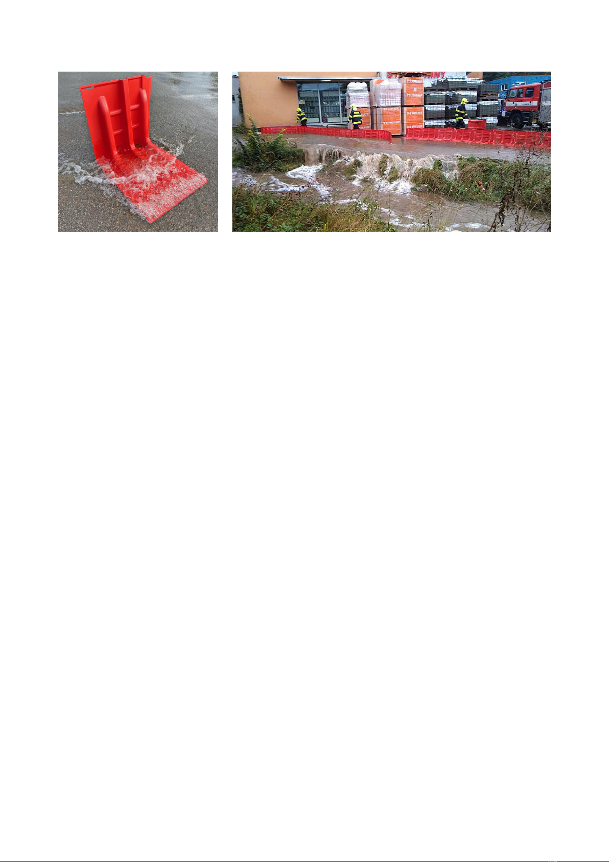
7. Flash flooding
The boxwall can also be used in flash flooding, when water is running fast over the streets.
When this happens the most obvious measure is to protect low entrances and vulnerable
objects by redirecting the water flow toward areas where flooding will cause less damage.
A similar situation can occur when snow is melting, and the water tries to take unacceptable
routes. As for the use in calm water, the boxwall should only be used on firm and even
surfaces.
If water is already running fast at the place of the intended action, the first measure would
be to place a number of boxes in the water flow, to break down the speed of it and reduce its
power. Put the boxes close to each other, facing upstream, but do not try to connect them.
They will be anchored directly by the weight of the water entering upon them.
Behind this protective row of boxes a continuous boxwall may then be assembled. When the
boxwall is completed, the front row of boxes can be removed.
This way the boxwall can be used to lead away watermasses in a controlled manner down
the streets, hereby reducing water levels and flood problems upstream. The boxwall does
not need to be in the shape of one continuous barrier, a number of short boxwalls can be
deployed just at the spots where the water needs to be redirected. For some streches short
overlapping sections of boxwall may also be an easier alternative to one long single barrier.
To divert the water off a street the boxwall may be deployed diagonally. The angle chosen,
in relation to the direction of the current, depends on the amount of water and its speed.
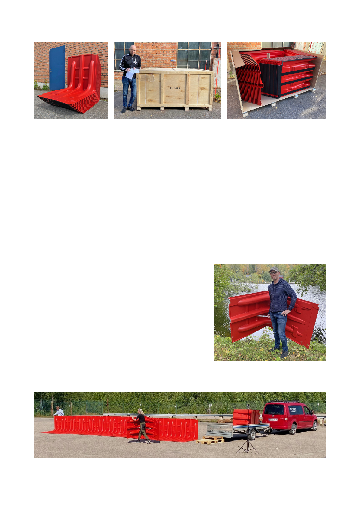
8. Handling
The boxes fit into each other, which makes it possible to stack them very compactly. Larger
volumes of BW102 are delivered in plywood cases measuring 2.15 x 1.47 x 1.14 meters
(85” x 58” x 44”). Each case contains 32 boxes, or approx. 29 meters (95’) of boxwall. The
cases are also intended for storing the boxes.
The cases are opened from the front. Start by loosening the seven buckles that hold the
front in place. Then gently pull out the top of the front using the handle. Then lift the entire
front, and remove it. Now all the boxes can be taken out, first the 16 on the right, then the
16 on the left.
The lid can also be removed, but it is not necessary. With the lid in place, the short sides are
also kept in place. The short sides and the backside are fixed and cannot be removed.
7 (8)
NOAQ BW102 1.0 201201
Also the loading of the case is made from the front, first
the 16 boxes that should stand to the left, then the 16
that should stand to the right.
A bar on the floor of the case helps to steer the first one
of the 16 right hand boxes in place. This box should
rest against the bar and be pushed all the way to the
backside of the case.
Using a special carrying stick the boxes can easily be
carried to wherever you want to have them.

9. After use
Disconnect the boxes. By leaning the right hand box (the one with the pin) against the left
hand one, they are easily disconnected.
Rinse the boxes clean using a garden hose or by rinsing them in water, and stand them on
their side to dry (when they are placed on the side the water runs off more quickly from the
pores in the sealing strip). If there is a risk of temperatures falling below zero, the boxes
must be taken indoors and stored in a heated area until all “soft parts” (soles and sealing
strips) have dried out properly.
8 (8)
NOAQ BW102 1.0 201201
Important!
Floods result from a course of events controlled by forces of nature that can only be controlled
to a limited degree. Furthermore, no two events are the same, which means that all protective
equipment must be used not only with good knowledge of its function and limitations, but also
with generally sound judgement. Those who provide the equipment, manufacturers, resellers,
hirers, etc. can never accept liability for the actual use and any possible personal injury or
damage to property that might arise.
Inspect all soft parts. Damaged or worn sealing strips can be
replaced, but worn soles should not, as the remnants may be
hard to remove completely.
If the soles have become very worn, additional pieces of sole
material can be attached to free spaces on the underside,
marked on the photo to the right. Boxes, where the soles have
suffered big damage, should be scrapped.
The boxes can be stacked to take up as little space as possible
during transport and storage. The plywood cases, in which
the boxes have been delivered, are also intended to be used
for storing them.
Table of contents


