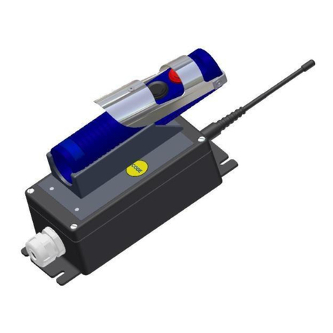
Delta DE212 GLOBAL Specification sheet

Delta RC AS Tlf. +47 33 44 83 90 Document item no: 02743
P.O. Box 1065
Søndre Kullerød 4A Web site: www.deltarc.no Last revision: 19.11.2018
Norway
Delta DE212
Wireless Deadman System
with
Differential Pressure Switch Function
for Aero Plane Refuelling Trucks and Dispensers
For license-free, global operation.
Operation and Installation Manual
- Approved transmitter

User and Installation Manual, DE212 GLOBAL
DELTA RC AS Page 2 of 36
Document 02743
CONTENTS
1. INTRODUCTION................................................................................................................................................ 3
1.1 SYSTEM HIGHLIGHTS ............................................................................................................................................3
1.2 SYSTEM CONFIGURATION ......................................................................................................................................3
2. INSTALLATION .................................................................................................................................................4
2.1 INSTALLATION OF THE RECEIVER............................................................................................................................4
Figure 2.1 Receiver and Transmitter in the drivers cabin.....................................................................................
4
2.2 RECEIVER UNIT CONNECTIONS ..............................................................................................................................5
2.3 CHANGING THE FUNCTION OF THE RECEIVER UNIT BY SW2........................................................................................8
2.4 ATEX CERTIFICATION..........................................................................................................................................9
3. OPERATION .................................................................................................................................................... 10
3.1 UNIT DESCRIPTION............................................................................................................................................. 10
3.2 FUNCTIONAL DESCRIPTION .................................................................................................................................. 11
3.2.1
Transmitter Unit:..................................................................................................................................
11
3.2.2
Receiver Unit .......................................................................................................................................
12
3.3 CODING THE TRANSMITTER AND RECEIVER UNITS.................................................................................................. 13
3.4 MAINTENANCE .................................................................................................................................................. 13
3.5 BATTERY RECHARGING....................................................................................................................................... 14
4. REPLACING THE BATTERY ................................................................................................................................... 15
5. OPTIONS, ADDITIONAL EQUIPMENT AND SPARE PARTS. .............................................................................. 16
5.1 OPTIONS........................................................................................................................................................... 16
5.2 ADDITIONAL EQUIPMENT ..................................................................................................................................... 16
5.3 SPARE PARTS.................................................................................................................................................... 16
5.3.1
Receiver front unit, parts identification ...............................................................................................
17
5.3.2
Transmitter parts identification ...........................................................................................................
17
6. WARRANTY CONDITIONS ............................................................................................................................... 18
6.1 APPROVED SERVICE STATIONS............................................................................................................................ 19
6.2 AGENTS............................................................................................................................................................20
7. TECHNICAL DATA........................................................................................................................................... 21
7.1 ATEX CERTIFICATES.........................................................................................................................................23
7.2 DECLARATION OF CONFORMITY ...........................................................................................................................32
7.3 DIMENSIONS......................................................................................................................................................33
8. ENVIRONMENTAL INFO ................................................................................................................................. 35

User and Installation Manual, DE212 GLOBAL
DELTA RC AS Page 3 of 36
Document 02743
Receiver unit
1. INTRODUCTION
The DE212 is a wireless Deadman control system, designed for aero plane refuelling trucks, hydrant
dispensers and road trucks.
The handheld Deadman switch is Ex approved according to the ATEX and IECEx regulations.
NOTE: Due to changed Ex requirements for the hand-held transmitter, the new handsets have grey
colour.
2.1 SYSTEM HIGHLIGHTS
•Operates wireless up to 30m from the refuelling vessel. Range can be adjusted in receiver.
•Integrated system, all you need for a safe Deadman operation is included.
•Several Delta wireless systems can operate in the same area without disturbing each other.
•Wireless operation improves efficiency and operational safety. No cable length limitations to move around
the aero plane and no cable to brake.
•No risk for false activation, each wireless handheld unit has a unique code.
•Flexible and modular system, easy to operate and maintain.
•Built in timer, no risk for the operator to manipulate the handheld unit.
•Integrated output for timer warning light and beeper.
•Emergency stop is included.
•External override function.
•Integrated interlock, ensure safe operation.
•Long battery capacity, more than 12 hours with a fully charged battery.
•Receiver has integrated intelligent charger.
•Unique coding system between handheld unit and receiver, easy maintenance.
2.2 SYSTEM CONFIGURATION
Wireless Deadman System Diagram
(Not to scale)
12/24VDC
Valve control
Emergency STOP
Interlock
Hose reel
Warning Light
External Override
DP switch
DP Reset/Override
DP Output
DP Warning light
External STOP
Warning Buzzer

User and Installation Manual, DE212 GLOBAL
DELTA RC AS Page 4 of 36
Document 02743
2. INSTALLATION
2.1 INSTALLATION OF THE RECEIVER
Installation in drivers cabin
External long range antenna (Optional)
Figure 2.1 Receiver and Transmitter in the driver’s cabin
The receiver unit with antenna is normally installed in the driver’s cabin, out of EX defined area.
The receiver must have connection to power supply/battery, 12 or 24VDC, and the fuel valve,
controlling the filling of the aircraft.
The receiver front panel is also the charging station for the transmitters battery. It is important that
the installation of the receiver is made so that it is easy to reach for the driver, in order to place the
transmitter for charging each time it has been used.
The orientation of the receiver is not important regarding the antenna. It must however be considered
that a lot of metal close to the antenna could reduce the radio signal strength, and reduce operational
range and also the functional stability.
If an external antenna must be used, up to 1,5m from the receiver unit, it must be connected by a
coaxial cable, and the antenna must be mounted vertically on a metal base.
If several antennas are installed on the truck, the DE212 antenna should be at a distance to other
antennas of no less than 1m.
NOTE: When installing the receiver unit, it should be considered to installed it in a place with
temperature within 0 and +50ºC. This is because, the transmitter batteries, NiMH does not charge
properly outside these temperatures.
If the temperature is outside these limits, it is recommended to use a mains battery charger, CH300
inside in a controlled temperature area. See section 5.2.

User and Installation Manual, DE212 GLOBAL
DELTA RC AS Page 5 of 36
Document 02743
2.2 RECEIVER UNIT CONNECTIONS
All connections to the Deadman system are made in the receiver unit.
Receiver connections
In order to get the most stable range between the receiver and the handheld transmitter, it is
recommended to install an antenna at the outside of the refuelling truck cabin. With an external
antenna the path between the two units is less dependent on radio shielding from the driver’s cabin
walls and items between the two units.
Antenna connection
HF-module
1. Timer Beeper output
2. Timer Warning output
3. Extra function
4. Deadman output
5. STOP
6. Interlock
7. Minus-pole for input voltage (-)
8. Plus-pole for input voltage (+)
9. Do not connect
10. DP Reset/Override
Receiver main board
1
2
3
4
5
6
7
8
9
10
Receiver connector P1
Input voltage fuse, 5A auto fuse
5
4
3
2
1
Receiver connector P3
1. External override
2. DP Switch
3. External STOP
4. Not in use
5. GND
SW2, Function select
(See chapter 3.3)
1
2
3
4
1
2
3
4
5
1. Do not connect
2. Do not connect
3. GND
4. DP Output
5. DP Warning Light
Receiver connector P2

User and Installation Manual, DE212 GLOBAL
DELTA RC AS Page 6 of 36
Document 02743
Connector
P1 in receiver
Functional description
Receiver function
Select, SW2
1
Timer beeper output
SW2-1: 2 min. timer ON/OFF
ON= timer active, OFF=No timer
2
Timer warning output
SW2-2: Extra function.
Simultaneous or no simultaneous operation with the
Deadman function.
ON = Simultaneous operation
3
Extra function, for
hose reel or pump speed control
4
Deadman output
SW2-4: DP Enable
5
Normally closed=activated output, opens
when STOP is pressed
6
Interlock (transmitter is charging)
Output is active when transmitter is
charging
7
Minus-pole for input voltage
8
Plus-pole for input voltage
9
Do not connect
10
DP Reset / Override
Receiver connections and functional selection.
Note: All outputs are 12 or 24V, same as the power supply voltage, when activated.

User and Installation Manual, DE212 GLOBAL
DELTA RC AS Page 7 of 36
Document 02743
Receiver connections, connector P3:
Functions installed with receiver software program: 02046
Conn.
P3
Functional description
1
External override
The Deadman function is active as long as this input is
low, connected to GND
SW2-3 : External override
ON= Ext. override active. OFF=Ext.
override disabled
2
Not in use, for future expansion.
Do not connect
3
External STOP.
Stops all functions in the receiver when connected to GND
This function is always enabled
4
Not in use, for future expansion.
Do not connect
5
GND, ground or common terminal.
Same as P1, term. 7
NOTES:
•Input voltage is 11 to 35 V DC. All outputs give input voltage when activated.
•NOTE: Input voltage above 35V, will shut down the receiver.
•Note that the potential between the minus pole and ground, must not be greater than 50VDC/AC peak.
•The timer warning output operates as follows: when the Deadman function is activated, the time warning
output also go active, supplying 12/24V out. When 30 seconds are left of the 2 min. time period, the
standard period, the output change from a steady output, to an off/on signal during the last 30 seconds of
the time period. The output is intended for connection to an indicating lamp, visible for the operator. The
on/off flashing lamp is intended to warn the operator to restart the time period.
•The timer beeper output is active only as long as the warning signal is flashing.
If external connection box is delivered, the connections are as follow:
Cable
marking
Receiver
connector
Function
YE-GN
Not in use
6
6
Interlock
5
5
STOP
4
4
Deadman output
3
3
Extra function
2
2
Timer warning
1
1
Timer beeper
7
7
Minus-pole, input voltage
8
8
Plus-pole, input voltage, 12/24VDC

User and Installation Manual, DE212 GLOBAL
DELTA RC AS Page 8 of 36
Document 02743
2.3 CHANGING THE FUNCTION OF THE RECEIVER UNIT BY SW2.
The function of the receiver unit can be changed according to operational requirements.
The following can be changed:
•SW2-1: Timed or no timed Deadman. ON is activated.
•SW2-2: Simultaneous or no simultaneous operation of the extra function, connection P1-3 when the
Deadman is activated.
•SW2-3: External override, active or off.
•SW2-4: Differential Pressure Switch on or off.
Standard factory setting of SW2 switches:
To change the settings:
1. Set the function switch, SW2 to the desired position
2. Take out the fuse, F1.
3. Press the receiver front button CODE while replacing the fuse. Press the CODE button for about 3
seconds, then the function is changed according to settings.
4. NOTE: SW2-2 must ALWAYS be set back to OFF after settings are changed.
SW2 Switch for function selection
NOTE: The connector for external override and STOP is normally not installed
This functions must be specified when ordering, see page 7.
2
3
4
1
1. Deadman timer enabled, 2 min timer (Default ON)
2. Simultaneous operation of extra function (Default OFF)
3. Deadman override input disabled (Default ON)
4. DP Enabled (Default ON)
OFF
ON

User and Installation Manual, DE212 GLOBAL
DELTA RC AS Page 9 of 36
Document 02743
2.4 EX CERTIFICATION.
The handheld unit, the TX212 transmitter is Ex approved, to verify this, look at the identification label
located under the handle.
Note that the certification is no longer valid if the TX212 is repaired by an un-authorized workshop, or
if the instruction given in this document is not followed.
The Ex-standards applied for this certifications are:
For the EU: II 2 G Ex ib IIC T4, EN 60079-0:2012 + A11:2013 and EN 60079-11:2012
IECEx: IEC 60079-0 Ed.6 and IEC 60079-11:2011
ATEX certification number: ZELM 03 ATEX 0139X
IECEs certification: IECEx ZLM 13.005X
The label tells the name of the producer and that the unit has an ATEX and IECEx certification, and is
allowed to be used in Ex environment, Zone 1.
The ART: is the article number of the product
The TYPE: is TX212-2S, given that it is a transmitter of the DE212 system.
2S says that it has two functions and STOP.
The S/N: is the serial number of the unit, which is a unique number.
The DATE: gives the production date.
The PROG: gives the software version of the transmitter.
The FREQ: gives the radio frequency of the transmitter.
The VOLT: gives the nominal battery voltage.
The IP: gives the protection grade of the transmitter

User and Installation Manual, DE212 GLOBAL
DELTA RC AS Page 10 of 36
Document 02743
OPERATION
3.1 UNIT DESCRIPTION
System units
The system unit includes the following parts:
•Portable and ergonomic transmitter, with battery and antenna.
•Receiver for fixed installation, with antenna connector, and cable gland for connection cable.
•Approx. 14 cm long antenna for installation on top of the receiver. OPTIONAL: external antenna with 1,5m
cable for external mounting.
•Delta CH300, 115/ 230V mains-powered battery charger for transmitter, OPTIONAL.
See section 5.2.
Receiver
Transmitter
Charging station
Cable inlet
Antenna

User and Installation Manual, DE212 GLOBAL
DELTA RC AS Page 11 of 36
Document 02743
3.2 FUNCTIONAL DESCRIPTION
3.2.1 TRANSMITTER UNIT:
The transmitter is controlled by a small microprocessor. It is always turned on in a standby mode, and
will therefore discharge the battery after 3 to 5 months, depending on the state of the battery, if it is
not recharged during that period of time.
A fully charged battery have a capacity of at least 12 hours of continues operation. The long operating
time is made possible by the Delta timeshare transmission system, WTT.
The battery is charged by the stainless steel contacts at the back side of the transmitter. The
transmitter must be charged on the charge station on the receiver front panel, or on a mains battery
charger, CH300 delivered by Delta. The charging connections, are protected from discharging of the
built-in battery.
The Deadman push-button is activated by a stainless steel handle as long as it is pressed.
The radio signal activates an output circuit in the receiver, supplying the output or the Deadman
function on the receiver’s connector. This is the output for the Deadman button for refuelling.
When the handle is released, the Deadman output is off after max 1,5 seconds.
If the STOP-button is pressed, all function stops instantly and the normally operated STOP output,
used for emergency stop, in the receiver goes off as long as the button is pressed.
The third push-button called, extra function, is normally used for hose reel in control, or pump RPM
control. Note that this function is on the standard delivery not possible to operate simultaneously with
the Deadman function. For simultaneously operation, the receiver must be reprogrammed.
There are two light diodes, LED on the front panel marked “TX”and “LB”.
The TX LED is yellow and is blinking when the transmission is active, and will continue to blink for a
short time after the operative push-button is released, sending an active stop signal to the receiver.
The LB LED is a dual function LED. It blinks with a red light when the battery is at low voltage or
capacity, and should be recharged. The transmitter can be used for about 15 min. after the red LED is
turned on. At a lower battery voltage, the TX LED is turned off, indicating that the transmitter has
stopped transmitting.
During normal operation, the LB LED is flashing green, indication that the connection with the receiver
is good.
The LB red LED is active only when the transmitter is activated. By pressing the Stop- button, the
battery can be tested during active transmission.
Handle
STOP Button
Extra function
Deadman
TX LED
LB LED
Battery

User and Installation Manual, DE212 GLOBAL
DELTA RC AS Page 12 of 36
Document 02743
The Stop button turns off the functions in the transmitter and sends an active STOP, turning instantly
off all the functions activated in the receiver. If the Deadman button is stuck, and the Stop-button is
pressed, the transmitter cannot be operated again before the damaged button or switch is changed.
Transmitter operation in low temperatures, lower than -20C can be performed, but not for a long
period of time. The transmitter must be warmed and charged at temperatures higher than 0C when
not in use.
Under normal use, the battery lifetime is 2-4 years.
3.2.2 RECEIVER UNIT:
The receiver front has a charging station for the transmitter unit, two LED indicators and one
push button marked “CODE”.
The energy charged to the battery, is calculated according to the time the transmitter has been used.
This will ensure high capacity and reduced overcharging of the battery.
The CH LED has three stages when the transmitter is placed to charge:
1: CH is dark. No action.
2: CH burns continues. Full charge current.
3: CH flashes. Indicates trickle charging, battery is full according to the last operation.
The green light diode, marked ON, indicates that a correct voltage is supplied and the receiver is ready
for operation. When coding the receiver and transmitter, this green LED flashes three times when the
code is accepted and stored in the receiver.
When the receiver is in operation, receiving an accepted telegram from transmitter, the yellow CH LED
is flashing rapidly.
CODE button
RX, CH, Charge
ON
Charge station
Charge contacts
Antenna

User and Installation Manual, DE212 GLOBAL
DELTA RC AS Page 13 of 36
Document 02743
3.3 CODING THE TRANSMITTER AND RECEIVER UNITS
In order to make the receiver execute a function, the code in the handheld unit, the transmitter, must be
transmitted to the receiver and correspond with the code stored in the receiver.
The DE212 system has 65536 different codes available. Each code and serial number is logged by the producer,
and a code is only used once. The transmitter is coded from the factory, while the receiver must be coded by the
user before starting operation as follows:
Press the yellow CODE button on the receiver front panel. Simultaneously press the red transmitter STOP button.
After about three seconds, the green ON-LED will flash three times, indicating that the code is stored. The
system is now ready to operate. The code is stored in the receiver even if the power is turned off.
Erasing the code:
The stored code in the receiver is erased by pressing first the Deadman button on the transmitter then the
CODE-button in the receiver, after some seconds, the green ON flashes 5 times, and the code is erased. To
maintain normal operation again, the receiver must be re-coded.
3.4 MAINTENANCE
This equipment should be kept as clean as possible at all times.
The transmitter, TX212 is an Ex, ATEX/IECEx classified unit, which can be used in hazard areas, zone 1. This
classification needs a special attention from the owner and user.
The TX212 design, both the electronic- and the mechanical part, is designed and controlled to meet the Ex
requirements. To keep the classification, and the security, the TX212 unit should be inspected regularly.
In case of a damage of the TX212, it should be send for repair to Delta RC AS or an appointed service station
immediately. All services and repairs of the unit, will be stored at the repair station, and by Delta RC AS store. In
case of an accident, it is possible to see the “history”of the unit.
Do not operate a TX212 which has a damaged housing.
A damaged unit must be taken out of service, and returned for repair.
Damages like cracks or holes in the cabinet plastic or rubber, are a safety risk and must be repaired before
further use.
The operator or owner can only change the battery module, following the instructions in chapter 4.
IMPORTANT NOTE:
Any unauthorized attempted repair, modification or other alterations of the product without prior
written permission from Delta RC AS will render both ATEX/IECEx approvals and warranties
invalid, and the responsible operator/owner will be held liable for any damages or injuries which
may occur.
Delta RC AS shall not be liable for reimbursements, claims and damages that may result from the
unauthorized repair, modifications or alterations of the product.

User and Installation Manual, DE212 GLOBAL
DELTA RC AS Page 14 of 36
Document 02743
3.5 BATTERY RECHARGING
1. Before the transmitter is used for the first time, it should be recharged with continues charging for 3 hours.
Place the transmitter in the charger on the receiver. Wait 30 seconds till the CH lamp start flashing, press the
CODE button on the receiver for some seconds, and the CH lamp will start to light constantly, indicating that
the transmitter battery is charged with maximum current. If the transmitter is left in the charger, this state
will last for 3 hours leaving a completely fully charged battery. Note, if the battery is not completely empty,
two hours charging is normally sufficient to start operation. Do not repeat the 3-hour full charging unless the
red LB lamp on the transmitter is flashing.
2. When the transmitter is placed on the receiver charge station, the transmitter battery will be recharged
according to the duration the transmitter has been used. The recharging will replace the used battery energy
actually used during operation. This type of charging will secure maximum battery capacity and lifetime.
Every time the transmitter is placed in the charger, it charges for 30 seconds with full current. After 30
seconds, and if the transmitter is unused, the charge current is reduced to maintenance charging and the CH
lamp will start flashing.
If the transmitter has been in operation longer than 5 minutes, the CH lamp will light constantly, indicating
that charging is at full current. When the battery energy has been restored, charging is reduced to
maintenance as long as the transmitter is in the charger. If the power of the receiver is switched off, stored
information regarding transmitter operation time, is erased.
3. The charging of the transmitter battery is controlled by the software in the receiver, and it is recommended
always to leave the transmitter for charging. The charging current is limited to 50mA during full charge, and
the charging time is regulated by the receiver software. The battery temperature will never rise above +50ºC
and will not be a hazard for the EX environment. In case of a short circuit of the battery connections, a build
in temperature and current fuse, in the battery will secure a temperature allowable in EX environment.
With a fully recharged battery the operational time is 12 hours. This means that the Deadman button on the
transmitter might be held operated for 12 hours before it stops transmitting.
Note that operation of the transmitter in low temperatures reduces the capacity of the battery down to 30%
of normal capacity at room temperature. At temperatures lower than -20C, the battery may “freeze” and
lose all its capacity.
4. NOTE: Charging the battery, should take place at temperatures not lower than 0ºC and not higher than
+50ºC. Charging outside these limits will results in very low charging current, or no charging of the battery at
all. The battery will however not be damaged.
When operating at low temperatures, lower than 0ºC, do not leave the transmitter in a cold driver’s cabin
overnight or for a long period of time. Take the transmitter inside to keep the battery warm. Charging of the
transmitter will normally be finished before the car is back to the depot.
It is recommended to use a CH300-230/115V mains charger, if the receiver is installed so that the
temperatures often is outside the recommended temperatures.
Use only Delta chargers for charging the transmitter, other chargers might overload the battery and the
ATEX/IECEx certification is no longer valid.
5. The type of battery used is a 3,6V 300mAh NiMH. The battery is a part of the end section of transmitter
house. The connection to the printed circuit board is by a small connector. Defective batteries must be
disposed at a proper place, where batteries can be disposed. Please see chapter 8 for further information.
A normal lifetime for a battery is approximately 500 recharging.
NOTE: After July 1. 2003, the new ATEX norms are activated. For the DE212 system, the battery module and
the transmitter circuit board must be replaced with parts produced according to this norms. This means that
repair of the TX212 must take place at Delta RC AS or by a Delta RC AS appointed dealer. Otherwise ATEX
certificate is no longer valid.

User and Installation Manual, DE212 GLOBAL
DELTA RC AS Page 15 of 36
Document 02743
REPLACING THE BATTERY
Note: The battery module 02465 and all replaceable parts of the transmitter, must be original parts delivered
by Delta RC AS. Otherwise the Ex certifications are lost, and the customer has to take all responsibilities. The
operator is only allowed to change the battery module, nothing else.
From December 2013, the battery module is changed, in accordance with the IECEx certification. The new
battery module for IECEx is 02465.
NOTE: Battery module 02465, cannot be replaced by the old 02166, but 02465 can replace the old 02166. Old
02166 battery modules are no longer valid for replacement and must be discarded.
WARNING:
THE BATTERY REPLACEMENT OPERATION MUST ALWAYS TAKE PLACE OUTSIDE
EX-AREA.
When the battery module has to be replaced, this procedure needs to be followed strictly:
•Verify that the old battery module 02166 is replaced by 02465.
Battery module 02465 must be replaced by 02465 only.
•Battery types other than specified must NEVER be used.
•Open the bottom end of the transmitter, by pressing the two lock-sections in.
•Pull the battery module gently out of the housing without jamming the O-ring.
•Disconnect the battery from connector marked “P3” on the PCB, by lifting the connector up.
See section 5.3.2
•Put a thin layer of non-corrosive, acid-free Vaseline on the new battery module O-ring
•Connect the new battery, and push the battery module back into the housing. Carefully make
sure the O-ring and connecting wires are not jammed during this operation.
•When the operation is finished, charge the battery for 3 hours, and test all functions.
See section 3.4
•Defective batteries must be disposed at a proper recycling facility.
Please refer to chapter 8 for further information.

User and Installation Manual, DE212 GLOBAL
DELTA RC AS Page 16 of 36
Document 02743
OPTIONS,ADDITIONAL EQUIPMENT AND SPARE PARTS.
5.1 OPTIONS
The DE212 is a deadman control system designed for aero plane refuelling trucks and
dispensers.
Both the receiver and transmitter are controlled by a microprocessor, making it possible to
tailor special functions for a customer.
The following units of the DE212 GLOBAL are available:
Order number
Functional description
02705
Transmitter TX212-2S Global2 2,4GHz with 1 extra function. Ex approved
01836
Receiver RXA6 Global 2,4GHz operation. 2min timeout. Standard delivery.
Note:The receiver has in a standard delivery with functions as follows:
•Timer controlled deadman. Running for 2 min. continuously. Warning light, or beeper tells
operator 30 sec. before end of the 2 min. to restart timer by a short release of the deadman
function.
•An interlock output signal when the transmitter is placed in the charge station on the receiver
front.
•Emergency STOP. An output signal as long as power is on.
The output is switched OFF when the STOP button on the transmitter is pressed.
•External Override. An input signal from an external unit, which overrides the deadman
handset. Emergency STOP on the handset is still active, even if external override is used.
5.2 ADDITIONAL EQUIPMENT
The standard delivery of a deadman control system comprises one receiver, one transmitter
and an 145mm antenna for installation on top of the receiver. For an installation require more
than this, the following are available:
5.3 SPARE PARTS
The following spare parts are available:
Order number
Item description
01855
Transmitter PCB TX212-2S Global 2,4GHz w/extra function. ATEX approved.
02704
Transmitter housing TX212-2S Global2 CH2 mount
02465
Transmitter battery module 3V6 NiMH 300mAh TX212. ATEX/IECEx approved.s
02052
Receiver PCB RXA mainboard
02345
Receiver PCB HF-module Global 2,4GHz.
01760
Receiver housing RXA Top CH2 mount
02258
Receiver housing RXA Bottom mount
02511
Receiver assembly set RXA Global
02477
Antenna for external installation, including 3m cable with FME connector
Order number
Item description
01780
Transmitter Charger CH300-2 110/230V AC.

User and Installation Manual, DE212 GLOBAL
DELTA RC AS Page 17 of 36
Document 02743
5.3.1 Receiver front unit, parts identification
5.3.2 Transmitter parts identification
Main connector P1
Input voltage fuse
Auto fuse 5A
Antenna
connector
Connector P3
(If applicable)
Battery module
#02465
Printed Circuit Board,
#01855
Battery module connector, P3
Charge connector, P2
Transmitter housing
#02704
Battery and charge connector
connected.
Printed circuit board shown partly inserted in
the housing.
During assembly, carefully make sure the O-
ring and wires are not jammed
between the battery module and housing.
Double-check polarity!
O-ring
HF module
connectors
SW2
Function select
Main printed circuit board
# 02052
HF module
# 02345

User and Installation Manual, DE212 GLOBAL
DELTA RC AS Page 18 of 36
Document 02743
WARRANTY CONDITIONS
Complaints
When receiving the product the buyer must inspect it, and eventually complain any obvious faults or
missing items within 8 days from reception. Acceptance of complaint will otherwise not be
considered. Complaints of any faults that could only first be discovered after mounting and testing
the product must be reported at once.
Warranty
The warranty covers only damages caused by material faults and manufacturing errors.
The guaranty ceases 12 months after the delivery date.
Delta RC AS or appointed repair workshop, is bound to repair and replace defect parts in its products,
free of charge, in its main workshop during its normal working hours. Packages being sent to and from
Delta RC AS are in the responsibility of the purchaser, as he is also economically responsible for
paying the transportation charges, toll, insurance and other charges related.
Should the warranty repair be done at the customer’s location, there will be charges for cost of
travelling, accommodation and dieting, conforming to the government’s assertions. There will also be
an additional charge of 50% of travelling time by the current repair regulations.
The warranty is cancelled if:
a) There has been done any modification or attempts in the product without a
prior written permission from Delta RC A/S.
b) The product has been handled wrongly or has not been maintained properly.
c) The payment conditions have not been fulfilled.
Repair work
NOTE: DE212 transmitters, TX212-2S are Ex, ATEX/IECEx approved. This means that repair work on
the transmitters must be performed by Delta RC AS or by a Delta RC AS appointed repair workshop. If
repair of a Ex approved part is done by a non-appointed repair workshop, the Ex approval is lost, and
the customer must take all responsibility.
Note that for the TX212 transmitter, the customer can change the battery unit only, according to
instruction in chapter 4
.
Repair work done after the warranty period is charged at full cost. Packages being sent to and from
Delta’s workshop are on the purchaser’s cost and risk.
If the repair work is done at the customer’s location, by Delta serviceman, there will be charges for
costs of travelling, accommodation, dieting, travelling time and hours of work.
Warranty exceeding 3 months after repair work is limited to cover only the fault that was repaired. A
new fault after the repair must be pointed by the customer.
Any other defect or missing part during this period is not covered by the warranty.
Should Delta offer a service unit during the warranty time, the purchaser pays for the transportation,
insurance and a weekly rent.

User and Installation Manual, DE212 GLOBAL
DELTA RC AS Page 19 of 36
Document 02743
6.1 APPROVED SERVICE STATIONS
Norway
Delta RC AS
P.O.Box 1065
NO-3204 Sandefjord
Phone: +4733448390
E-mail: sales@delta-RC.no
Germany
Henniger Electronics
Untere Dorfstrasse 24
DE-38304 Wolfenbüttel
Germany
Phone: +495331904103
Fax: +495331904115
E-mail:
a.henniger@henniger-electronics.de
UK and Ireland
Aljac Fuelling Components Ltd
Pitfield House, Station Approach,
Shepperton
Middlesex TW17 8AN
U.K.
Phone: +441932269869
Fax: +441932269230
E-mail:
Sweden
BeWe Elektronik
P.O. Box 78
SE-43905 Åsa
Sweden
Phone: +46340655677
Fax +46340655677
E-mail:
Denmark
Temac Automation ApS
Kastanie Alle 16
DK-6760 Ribe
Denmark
Phone: +45 43443900
Fax +45 43447800
E-mail: [email protected]
Web: www.temac.dk

User and Installation Manual, DE212 GLOBAL
DELTA RC AS Page 20 of 36
Document 02743
6.2 AGENTS
Thailand
Aviation Enterprise Co.
54/116 Soi3. Baranee Village
Klongsam. Klongluang, Pathum Thanee
12120 Bangkok
Thailand
Phone: +6628327253
Fax: +6625997662
E-mail:
aviation_enterprise@yahoo.com
France
Marco Tech
5, Rue Jean Jaures
FR-33310 Lormont
France
Phone: +33557306300
Fax: +33557306301
E-mail: [email protected]u
Canada/Northern America/Southern America/Caribian Area
GoExport Ltd.
5795, avenue De Gaspé, bureau 214
Montréal (Québec) H2S 2X3
Canada
Phone: +1 514 227 8490
E-mail : info@goexport.ca
Other manuals for DE212 GLOBAL
3
Table of contents
Other Delta Control System manuals