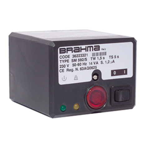
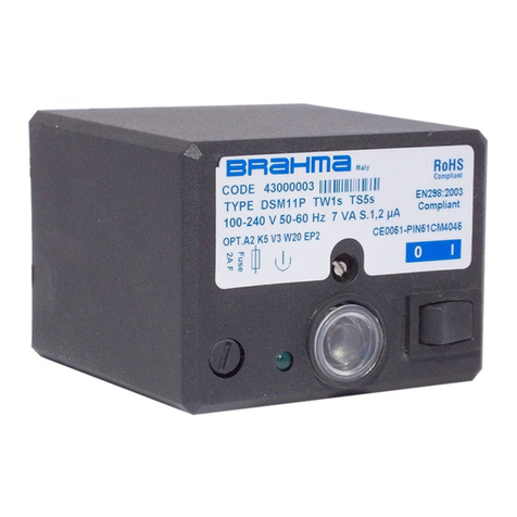
BRAHMA EUROFLAT Series User manual

EUROFLAT SERIES
TYPES MT11 MT31
AUTOMATIC GAS BURNER CONTROL
SYSTEMS FOR GAS BURNERS AND GAS
BURNING APPLIANCES WITH OR
WITHOUT FAN MONOELECTRODE WITH
EXTERNAL IGNITION DEVICE.
Application
This range of electronic gas burner control systems has
been designed specifically for atmospheric and fan assisted
burners for intermittent operation (systems for non-
permanent operation).
These types of automatic burner control units differ from the
standard model essentially in the operating cycle and in the
features of the ignition-detection device. Due to the design
and the technical-structural characteristics, the controls of
this series can be used in general in gas firing installations
with atmospheric burner.
Features
Table 1 shows the main features of this series. Other
important features are:
− in accordance with EN298 (European standard for
automatic gas burner control systems);
− flame monitoring by the rectification property of the
flame: ionization;
− electrical service life at max. loading >250.000
operations;
− two independent safety contacts in series on the gas
valve output;
− electronic ignition device (transformer TC1 – TD1
series).
TABLE1 BURNER
single flame
atmospheric without fan
atmospheric with fan
classification code according to
EN298
MT11 * * AMCLXN
MT31 * * FMCLXN
3999_r01
1/4

TECHNICAL DATA
Supply Voltage: 230V∼50-60Hz
Operating temperature range: -20°C +60°C
Ambient humidity: 95% max at 40°C
Protection degree: IP 00
Times:
- Waiting or pre- purge time (TW):
1,5/3/5/10/20/30/40 s
- Safety time (TS): 3/5/8/10/20/50/60 s
- Ignition time (TSP): (40% di TS) s
- Drop out time on running flame failure: < 1 s
The times given on the burner control label correspond to
the values guaranteed. The actual values differ slightly from
the values given, warm time is in fact longer and safety time
shorter than their nominal values.
Power consumption, at starting up:
atmospheric burner 13 VA
atmospheric fan-assisted burner 15 VA
Contact rating: I max
-Thermostat: 4A cos ϕ≥0.4
-VG1: 0.5 A cos ϕ≥0.4
-Fan: 1A cos ϕ≥0.4
-Alarm: 0,5 A cos ϕ= 1
Max. length of the cables of
external components: 1 m
Fuse rating internal: 4A T
Fuse rating external: 3,15 A F
Flame control:
The ionization flame detector device makes use of the
rectification property of the flame.
The ionization flame detector device is not a safe to touch
output (no provision with protective impedances).
-Minimum ionization current: 0.5µA
1.2µA
-Recommended ionization current:
3 ÷ 5 times the minimum ionization current
-Max length of the cable: 1 m
-Minimum insulation resistance of cable and flame
detector device to earth: ≥50MΩ
-Max. parasitic capacitance of
detection probe: ≤1nF
-Max. short circuit current: < 200µA AC
Weight: 200 g
CONSTRUCTION
The enclosure made of plastic material protects the control
from mechanical damage, dust and dirt from the conditions
of installation.
The printed circuit board dimensions have been reduced by
means of a module with surface mounted components.
A varistor protects the control from voltage transients on the
mains supply. An internal fuse protects the relays of the
control in case of short circuits on the outputs (valve, fan,
lock-out signal and ignition / detection device). This is not an
accessible fuse and the control must be protected with a
fuse of the fast blow type suitable to the load connected and
never exceeding 3,15A.
Overall Dimensions
The following figure Fig. 1 shows the overall dimensions of
the controls.
Fig. 1
Accessories
The control units are usually supplied with a kit of female
connectors and/or reset button. Do no fit terminals and
female connectors of different types.
These accessories can be supplied upon request (see
Fig.2).
RESET BUTTON DRILLING PLAN
COD.: 81020980 Reset 1
Lock-out s. 2
3 Neutral
FEMALE CONNECTORS TERMINALS
STOCKO: MKF 2800 STOCKO: RFB 7851
STELVIO:BS95/... STELVIO: CT84
Fig.2
Connection
Using non reversible connectors with different number of
poles makes the connection easy and reliable.
One–way fast–on connectors of different sizes permit their
easy installation and replacement.
Regarding the connection of the control units, provisions
such as strain reliefs, sufficient earth terminals and neutral
terminals should be present in the appliance or in external
connection boxes.
M4 SCREW
SLOT
2/4 3999_r01

The controls are prearranged to operate with only one
electrode for ignition and flame detection (the ignition
electrode also makes the flame detection function by means
of wire connection between pin 16 of J4 and fast-on J5 as
shown in figure 4a); they can also correctly operate with
separate ignition electrode and detection electrode (as
shown in figure 4b).
DIRECTIONS FOR THE USE
− For technical-safety reasons a regulation shutdown must
occur every 24 hours (systems for non-permanent
operation).
− Automatic controls are safety devices and shall not be
opened. Responsibility and guarantee of the
manufacturer is invalidated if the control is opened.
− The control must be connected and disconnected only
without the main power.
− The control can be mounted in any position.
− Avoid exposure of the control unit to dripping water.
− Ventilation and the lowest temperature ensures the
longest life of the control.
− Make sure that the type (code and times) you are using
is correct before installing or replacing the control.
− The gas appliance in which the control is installed must
provide adequate protection against the risk of electrical
shock (at least IP20).
Electrical installation
− The applicable national regulation and European
standards (e.g. EN60335-1/EN50165) regarding
electrical safety must be respected.
− Live and neutral should be connected correctly, a
mistake could cause a dangerous situation, i.e. the
valve would still be live with the thermostats and limits
switched off. Besides, if live-neutral polarity is not
respected the control performs a non-volatile at the end
of the safety time at starting up.
− Before starting check the cables carefully. Wrong
connections can damage the control and compromise
the safety.
− Take great care while connecting the lock-out signal and
reset button: an inversion in the connection can damage
the control.
− The earth terminal of the control, the metal frame of the
burner and the earth on the mains supply must be well
connected.
− Use an ignition cable as short and straight as possible
and keep it far from other conductors.
− Using the control with separate detection electrode, a
heat resistant cable and detection probe must be used,
well insulated to the ground and protected from possible
woisture (or water in general).
IMPORTANT: in the event of "partial" short circuits or
bad insulation between phase(s) and earth the voltage
on the ionization device can be reduced until it causes
the lock-out of the control.
Checking at start
Always check the control before the first start and also after
substitutions or a long period of non operation of the
system. Before any ignition attempt make sure that the
combustion chamber is free from gas.
Then make sure that:
− if the attempt to start occurs without the gas supply the
control performs a non-volatile or volatile lock-out after
TS;
− when stopping the gas flow (while the control is in
running state) supply to the gas valve is interrupted
within 1 second and after a recycling, the control
proceeds to a non-volatile lock-out;
− operating times and sequence are suitable;
− the level of the flame signal is sufficient, see Fig.4 for the
measuring test;
− the intervention of limiters or safety devices causes a
safety shut-down according to the application.
Fig.3
Operation
At every start the control unit proceeds to a self-checking of
its own components.
In the type with control of the fan, before the elapsing of pre-
purge time (TW), the air pressure switch contacts are
checked to prove their "no air flow" state.
Only if the test is positive the fan is started and with the air
pressure switch in "air flow" state, pre-purge time begins.
At the end of wanting or pre-purge time the gas valve is
supplied and the ignition device, so that safety time TS and
ignition time TSP begin.
The ignition device is kept in operation for 40% of the safety
time TS under all operating condition (time TSP ending). If
during remaining time TS, the control unit will keep the gas
valve supplied until a flame failure occurs (followed by a
recycling) or the regulation ring opens. On the contrary, if
the control doesn't detect a flame by the end of TS, it
proceeds to non-volatile (or volatile) lock-out, the gas valve
is switched off while the lock-out signal output is supplied.
The attached diagrams are useful to understand how each
control operates.
Reset of the control
When a control has gone to non-volatile or volatile lock-out,
an interval of 10 seconds should be allowed before
attempting to reset the control unit; if this time is not
observed then the control may not reset correctly.
In general, resetting of the appliance must occur in sight and
in the near vicinity of the appliance. Resetting must also
occur by means of a conscious manual action and not by
means of automatic device like thermostats or timers.
Please note that it is allowed to combine the reset button
together with the main switch on the appliance. In this case
the alarm light will have to be installed too.
IGNIT. / DETEC.
ELECTRODE
J4 J5 J6
A
-+
I ion
BROWN
BLUE
G/V
3999_r01
3/4

BRAHMA S.p.A.
Via del Pontiere, 31
37045 Legnago (VR) – ITALY
Tel. +39 0442 635211 – Fax +39 0442 25683
2011/06/07 subject to amendments without notice
http://www.brahma.it
CONNECTION DIAGRAMS
F 3.15A
L N
SB
RESET
N
1 2 3 4 5 6 7
J1
N
VG1
13 14 15
J3
TYPE MT11 TYPE MT31
PA V
J2
N
8 9 10 11 12
F 3.15A
L N
SB
RESET
N
1 2 3 4 5 6 7
J1
N
VG1
13 14 15
J3
IGNIT. / DETEC.
ELECTRODE
BROWN
BLUE
G/V
1619 18 17
J4 J5 J6
F 3.15A
L N
SB
RESET
N
1 2 3 4 5 6 7
J1
N
VG1
13 14 15
J3
TYPE MT11 TYPE MT31
PA V
J2
N
8 9 10 11 12
F 3.15A
L N
SB
RESET
N
1 2 3 4 5 6 7
J1
N
VG1
13 14 15
J3
Fig. 4a CONNECTION DIAGRAMS WITH SINGLE IGNITION / DETECTION ELECTRODE
Fig. 4b CONNECTION DIAGRAMS WITH SEPARATE DETECTION ELECTRODE
IGNITION
ELECTRODE
BROWN
BLU
G/V
1619 18 17
J4 J5 J6
DETECTION
ELECTRODE
IGNIT. / DETEC.
LECTRODE
BROWN
BLUE
G/V
1619 18 17
J4 J5 J6
IGNITION
ELECTRODE
BROWN
BLUE
G/V
1619 18 17
J4 J5 J6
DETECTION
ELECTRODE
T
ION
Tw Tsp
Ts Ts
Tw Tsp
TYPE MT11
Ts
TYPE MT31
Tw Tsp Tw
Ts
Tsp
SB
VG1
SB
ION
VG1
T
PA
V
TR
TR
PA ION SB
TR
VG1
V
T
THERMOSTAT FAN AIR PRESSURE
SWITCH FIRST GAS
VALVE EXTERNAL IGNITION
DEVICE FLAME
SIGNAL
LOCK - OUT
SIGNAL
OPERATING CYCLES
4/4 3999_r01
NOTE: the limit thermostat has to be wired in series to the live
ATTENTION
-
> Company Brahma S.p.A. takes no responsibility for any damage resulting from Customer's tamp
ering with the device.
This manual suits for next models
2
Other BRAHMA Control System manuals


