Noble 495HTGW22 User manual

NOBLE WAREWASHING - GLASSWASHER - 495HTGW22
USER MANUAL
GENERAL INSTRUCTIONS
FOR INSTALLATION, USE
AND MAINTENANCE
Glasswasher
495HTGW22
12318950
495HTGW22 User Manual Revised 09/22
9900857
CONFORMS TO UL STD. 921
CERT. TO CSA STD. C22.2 Nº168
9900857
CONFORMS TO STD.
NSF/ ANSI 3-2019
READ FIRST
THIS MANUAL MUST BE RETAINED FOR FUTURE REFERENCE.
READ, UNDERSTAND AND FOLLOW THE INSTRUCTIONS AND
WARNINGS CONTAINED IN THIS MANUAL.
WARNING
IMPROPER INSTALLATION, ADJUSTMENT, ALTERATION, SERVICE OR
MAINTENANCE CAN CAUSE PROPERTY DAMAGE, INJURY OR DEATH.
READ THE INSTALLATION, OPERATION & MAINTENANCE INSTRUCTIONS
THOROUGHLY BEFORE INSTALLING OR SERVICING THIS EQUIPMENT.
WARNING HAZARDOUS
VOLTAGE
PLEASE READ
INSTRUCTIONS
PROTECTIVE
EARTH
EQUIPOTENTIAL
BONDING
Model: Purchased From:
495HTGW22
Serial: Location:
Date Purchased: Date Installed:
Purchase Order: For Service, call:

TABLE OF CONTENTS
3
1. INDEX
1. INDEX ..................................................................................................................................... 3
2. GENERAL INFORMATION AND WARNINGS ....................................................................... 4
3. GENERAL MEASUREMENTS AND CONNECTIONS .......................................................... 5
4. QUICK STARTUP GUIDES ................................................................................................... 6
5. ELECTRICAL DIAGRAMS..................................................................................................... 7
6. ELECTRIC DIAGRAMS LEGEND ......................................................................................... 8
7. PRODUCT DETAILS ............................................................................................................. 9
7.1 Technical specications ................................................................................................ 10
8. INSTALLATION INSTRUCTIONS ........................................................................................ 11
8.1 Removal of packaging ................................................................................................. 11
8.2 Positioning and leveling ............................................................................................... 11
8.3 Electrical connection .................................................................................................... 12
8.4 Water connection ......................................................................................................... 13
8.5 Drainage connection..................................................................................................... 14
8.6 Liquid rinse aid dispenser ............................................................................................ 16
8.7 Detergent dispenser .................................................................................................... 16
8.8 Recycling ..................................................................................................................... 18
9. USE AND MAINTENANCE INSTRUCTIONS ...................................................................... 19
9.1 Operation ..................................................................................................................... 19
9.1.1 Control panel symbols .............................................................................................. 19
9.1.2 Switching on the machine ......................................................................................... 19
9.1.3 Hygiene practices ..................................................................................................... 20
9.1.4 Preparation of the dishes .......................................................................................... 21
9.1.5 Selecting the wash cycle .......................................................................................... 21
9.1.6 Stopping the wash cycle and end of wash cycle ...................................................... 22
9.1.7 Drainage of the machine ........................................................................................... 22
9.1.8 Switching off the machine ......................................................................................... 24
9.1.9 Cleaning the machine at the end of the day ............................................................. 24
9.2 Cleaning and Maintenance Instructions ....................................................................... 24
9.2.1 Routine maintenance ................................................................................................ 24
9.2.2 Rinse aid and detergent ............................................................................................ 25
9.2.3 Prolonged non use .................................................................................................... 25
10. FAULTS AND TROUBLESHOOTING ................................................................................. 26
GENERAL INFORMATION AND WARNINGS
4
2. GENERAL INFORMATION AND WARNINGS
This manual has been created to help you understand the operation, installation and maintenance
of the machine. It contains all the necessary information and warnings to ensure that the appliance
is installed and used correctly, together with information about the characteristics and possibilities
offered, so that you may enjoy your machine to the fullest.
BEFORE STARTING THE APPLIANCE, PLEASE READ THE INSTRUCTIONS
CONTAINED IN THIS MANUAL CAREFULLY.
The manual should be kept safely on hand for future reference.
If the machine is sold or transferred, please pass the manual to the new user.
THIS APPLIANCE IS EXCLUSIVELY FOR PROFESSIONAL USE AND SHOULD ONLY
BE USED BY QUALIFIED PERSONNEL.
• The positioning and installation, and all repairs or modications, should always be carried out
by an AUTHORIZED TECHNICIAN, in accordance with the applicable local legislation. The
manufacturer does not accept liability if the machine is incorrectly installed.
• The installation, incorrect adjustment, inappropriate maintenance or use of the appliance may
cause material damages and injuries.
• The dishwasher should be correctly leveled, and care taken to ensure that none of the electric
cables, water or drainage hoses are trapped or kinked.
• DO NOT climb on top of the dishwasher or place heavy objects on top of the machine as it has
only been designed to bear the weight of the basket of plates to be washed.
• The dishwasher is designed for washing plates, glasses and other kitchenware with
traces of human food. Any other objects must not be washed in the machine.
• If your machine breaks down, please contact authorized dealer.
• Unqualied or unauthorized personnel must NOT try to repair the machine.
• Use of spare parts other than original parts will cancel the guarantee.
• During all maintenance operations, the dishwasher must be disconnected from the main
power supply at the mains power switch, and the water intake tap must be closed.
• Abrasive or corrosive products, acids, solvents and chlorine-based detergents must
NOT be used to clean the appliance, as this may damage the components.
• Detergents or sanitizers shall not be manually added to the machine.
• This appliance has been designed for use in ambient temperatures between 41 ºF
and 104 ºF
Failure to comply with these instructions or the incorrect use of the appliance shall
relieve the manufacturer of any obligations regarding the guarantee or possible
claims.

GENERAL MEASUREMENTS
5
3. GENERAL MEASUREMENTS AND CONNECTIONS
Glasswasher 495HTGW22
A B C D E F G
Water Inlet Drain Hose
Power Supply
Cable Strain
Relief
Connection
Strip (Inside) Rinse Aid Inlet Detergent
Inlet
Equipotential
Bond

QUICK STARTUP GUIDES
6
4. QUICK STARTUP GUIDES
8
ELECTRICAL DIAGRAMS
7
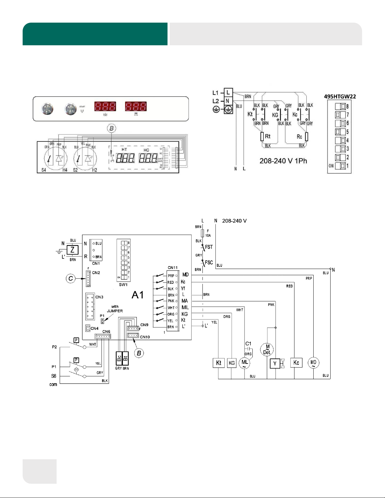
5. ELECTRICAL DIAGRAMS
ELECTRICAL DIAGRAMS LEGEND
8
6. ELECTRICAL DIAGRAMS LEGEND
11
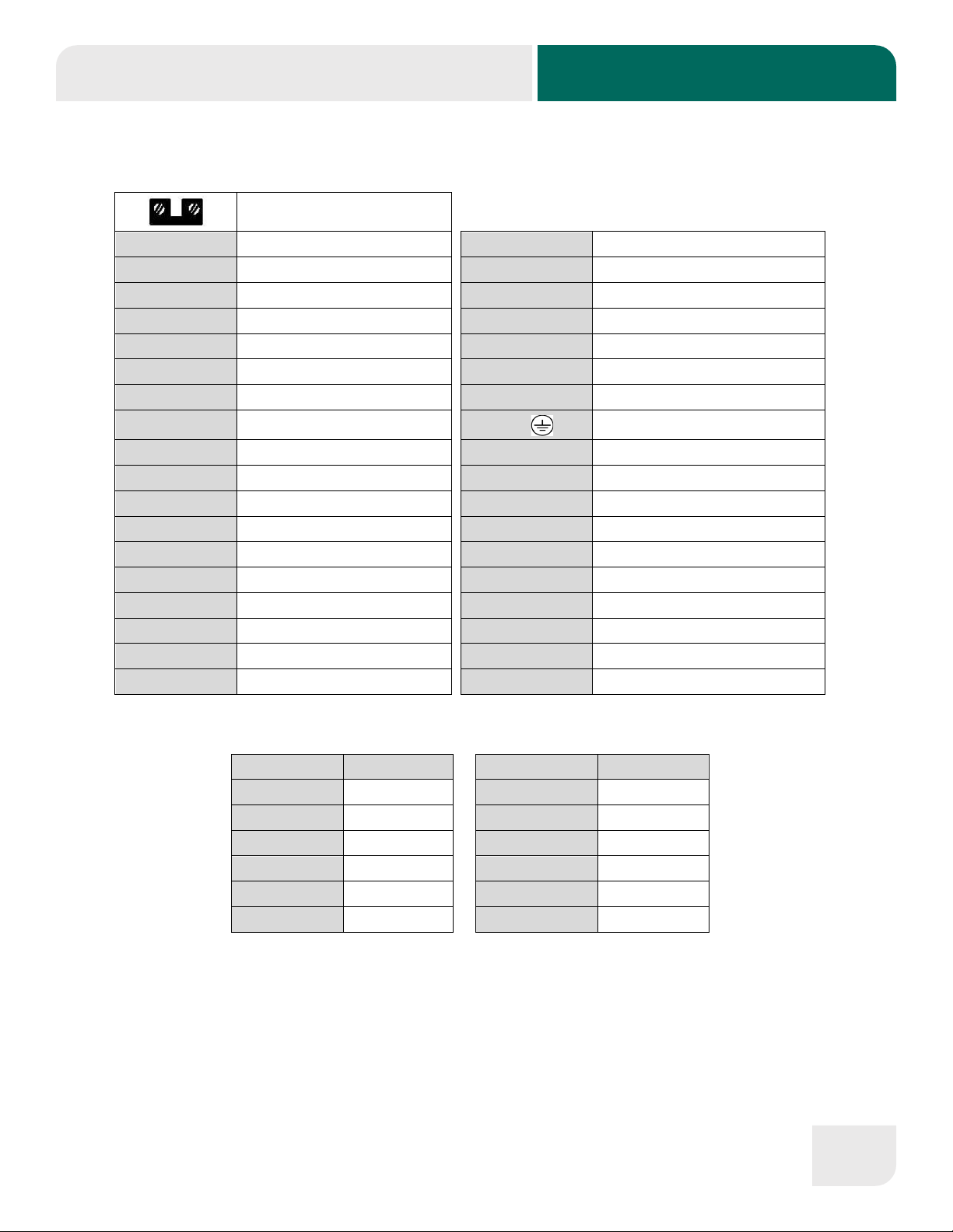
5. ELECTRIC DIAGRAMS LEGEND
Terminal block bridge
A1, A2
Electronic Board
MD
Drain Pump
A1-P1
Electric Bridge / Jumper
MDet
Detergent Dispenser
Bc
Boiler temperature probe
ML, ML1, ML2
Wash Pump
Bt
Tank Temperature Probe
N
Neutral
C1, C2
Capacitor
P1
Tank Pressure Switch
F
Fuse
P2
Tank Safety Pressure Switch
FSC
Boiler Safety Thermostat
P3
Boiler Pressure Switch
FST Tank Safety Thermostat PE /Earth Ground
H1, H2, H3
Cycle Light
RC
Boiler Heating Element
H4
Power On Light
RT
Tank Heating Element
HC
Boiler temperature Display
S1, S2, S3
Program/Cycle Push button
HT
Tank Temperature Display
S4
ON/OFF Push button
KC
Boiler Heating Contactor
S6
Door Switch
KG
Main Relay
SW1
DIP-SWITCH
KT
Tank Heating Contactor
TRF
Transformer
L, L1, L2, L3
Power Supply Phases
Y
Tank Filling Solenoid valve
MAbr
Rinse Aid Dispenser
Yf
Boiler Filling Solenoid valve
MA
Rinse Pump
Z
EMC Filter
COLOR COLOR
BLK, bk, n
Black
PNK, pk, rs
Pink
BLU, bl, a
Blue
PRP, pr, vi
Purple
BRN, bn, m
Brown
RED, rd, r
Red
GRN, gn, ve
Green
WHT, wh, b
White
GRY, gy, g
Grey
YEL, yw, am
Yellow
ORG, or, na
Orange
YW/GN, am/ve
Yellow / green
PRODUCT DETAILS
9
7. PRODUCT DETAILS
As it is an industrial product, it is characterized for having a high dishwashing capacity. The
characteristics of the product are listed below to help you understand your machine better.
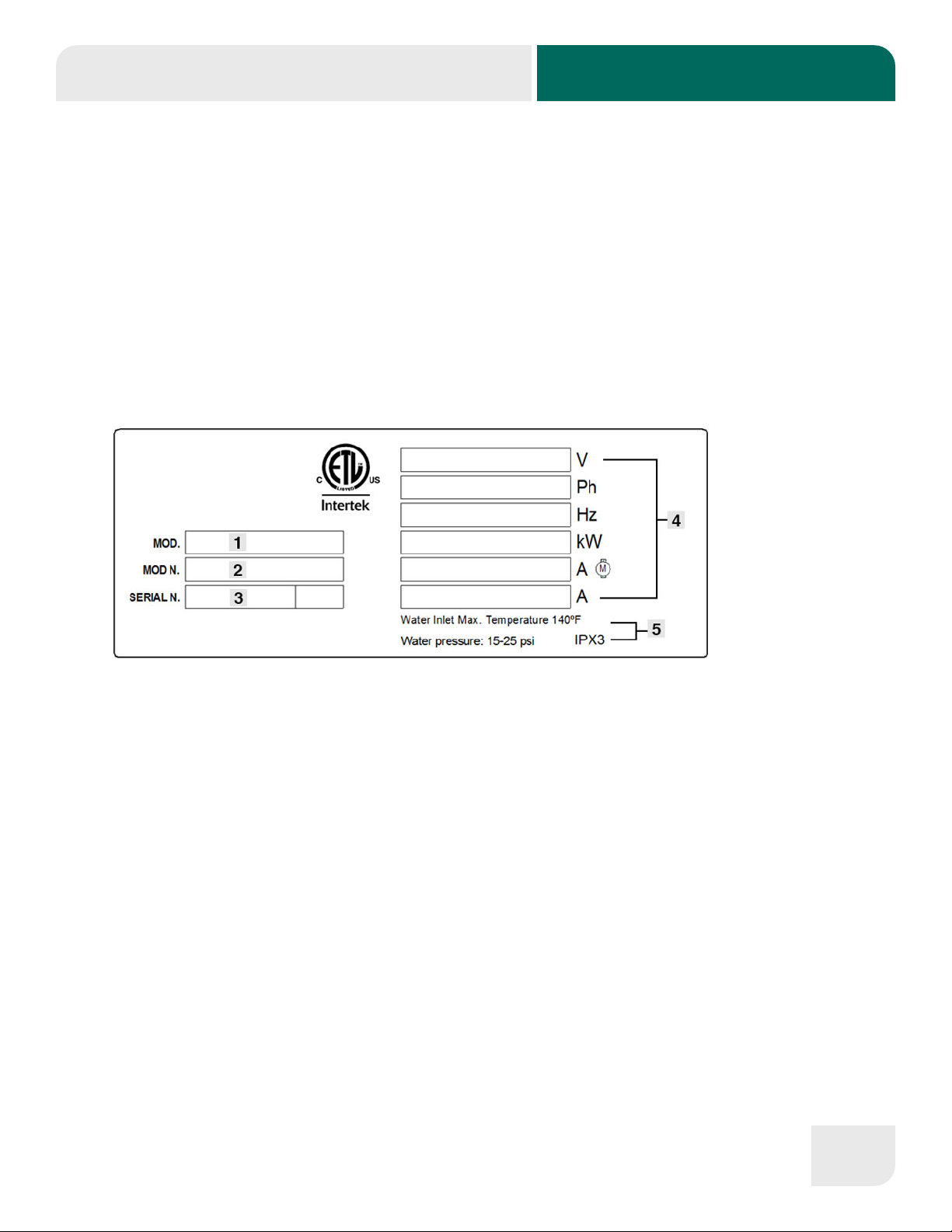
All the appliances have a nameplate which identies the appliance and indicates its technical
characteristics. Under no circumstances should the data plate be removed from the unit. The data
plate is essential to identify the particular features of your machine and is of great benet to installers,
operators and maintenance personnel. It is recommended that, in the event the data plate is removed,
you copy down the essential information in this manual for reference before installation.
DATA PLATE
☐1: APPLIANCE MODEL NAME
☐2: APPLIANCE REFERENCE
☐3: SERIAL NUMBER + MANUFACTURE DATE
☐4: ELECTRICAL SPECIFICATIONS
☐5: WATER INLET SPECIFICATIONS
These details should be quoted when the technical service is called.
PRODUCT DETAILS
10
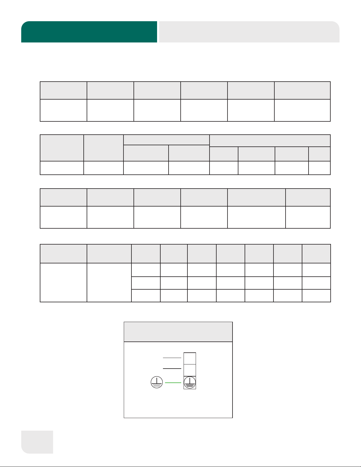
7.1 Technical Specications
MODEL RACKS PER
HOUR
WASH TANK
(Gal)
GALLONS PER
CYCLE
WATER INLET
MAX TEMP.
WATER INLET
PRESSURE
Glasswasher -
495HTGW22 22 4 0.53 140º F At Pressure Gauge
20psi ± 5psi
MODEL WIDTH DEPTH HEIGHT MAX CLEARANCE
FOR DISHWARE RACK
Glasswasher -
495HTGW22 20 7/8” 26 3/4” 35 10 5/8” 16” x 16”
MODEL WASH PUMP
MOTOR
HEATING ELEMENTS OPERATING CYCLE TIME (s)
WASH TANK (kW) BOILER (kW) WASH DWELL RINSE TOTAL
Glasswasher -
495HTGW22 1/3 hp 2.15 3 101 5 14 120
MODEL CONNECTION
TYPE
VOLTAGE
(V)
TOTAL
LOAD (A)
TOTAL
POWER
(kW)
PUMP
LOAD (A)
PUMP
POWER
(kW)
TANK
POWER
(kW)
BOILER
POWER
(kW)
Glasswasher -
495HTGW22
208-240V
60Hz
1Ph
208V 12.03 2.50 1.02 0.21 1.64 2.29
220V 12.73 2.80 1.08 0.24 1.83 2.56
240V 13.88 3.33 1.18 0.28 2.18 3.05
Glasswasher - 495HTGW22
L1
L
L2 N
208-240V, 60HZ, 1PH

INSTALLATION INSTRUCTIONS
11
8. INSTALLATION INSTRUCTIONS
The dishwasher shall be installed in accordance with local codes, or in the absence of
local codes, installed in accordance with the applicable requirements in the National
Electrical Code, NFPA 70, Canadian Electrical Code (CEC), Part 1, CSA C22.1, and
Standard for Ventilation Control and Fire Protection of Commercial Cooking Operations,
NFPA 96.
The positioning and installation, and all repairs or modications, should always
be carried out by an AUTHORIZED TECHNICIAN, in accordance with the applicable
legislation of the country.
The installation, incorrect adjustment, inappropriate maintenance or use of the appliance
may cause material damages and injuries.
8.1 Removal of packaging
Remove packaging from the machine and check for damage during transportation. If any damage is
observed, immediately notify the supplier and the transport company. In the event of doubt, do not use
the machine until the problem has been assessed.
Packaging (plastic, expanded polyurethane, staples, etc…) must not be left
in the reach of children, they are a potential hazard.
The machine should be moved using a fork-lift truck or similar to avoid damage to the structure.
Transport the machine to the installation location and then remove packaging. All the packaging
can be recycled. Dispose of packaging correctly.
8.2 Positioning and leveling
This appliance has adjustable feet. This is done by turning the leveling stands to the desired height.
For optimum operation, it is essential that the machine is correctly leveled. The ooring on which the
machine is to be installed must be able to bear the full weight of the machine.
INSTALLATION INSTRUCTIONS
12
8.3 Electrical connection
• Refer to the wiring diagram, the machine data plate and technical specications for service
size requirements.
• Check that the mains voltage corresponds to that indicated on the nameplate.
• The power-supply cord shall be Type S, SE, SO, SOO, ST, STO, or STOO (with or without
W at the end).
• The power supply cord wire size must be suitable for the rated current of the machine
(amperage load). Use copper conductors only.
• The appliance must be grounded using the ground connection of the terminal block of the
appliance.
• An all phase Circuit Breaker must be installed near to the appliance between the power
supply and the appliance in accordance to required consumption guidelines. Switch the
circuit breaker to “OFF” when servicing the appliance. It is recommended that it has lockout-
tagout capabilities. The manufacturer will not be held liable for damage originated by failure
to observe this requirement.
• A suitable safety switch / Residual current device must be installed near the appliance
between the power supply and the appliance. The manufacturer will not be held liable for
damage originated by failure to observe this requirement.
• If any faults are observed during the installation, the supplier should be notied immediately.
When a number of appliances are installed in line, they should all be ground bonded at the point
provided for that purpose.
To access the connection strip when a permanent connection needs to be made, release the cover
of the machine’s front (see Section 2 - General Measurements and Connections). The power cable is
connected to the connection strip. It is also possible to change the machine conguration here.
The manufacturer will not be held liable for any personal or material damage to the
machine resulting from incorrect installation or failure to comply with the manufacturer’s
specications.

INSTALLATION INSTRUCTIONS
13
It is the personal responsibility and obligation of the customer to contact a qualied
electrician to assure that the electrical installation is adequate.
8.4 Water connection
The new hoses supplied with the appliance should be used (do not reuse old hoses).
Before connecting the machine to the water supply, the water quality should be tested.
Recommended water quality:
17
•Refer to the wiring diagram, the machine data plate and technical specifications
for service size requirements.
•Check that the mains voltage corresponds to that indicated on the nameplate.
•The power-supply cord shall be Type S, SE, SO, SOO, ST, STO, or STOO (with
or without W at the end).
•The power supply cord wire size must be suitable for the rated current of the
machine (amperage load). Use copper conductors only.
•The appliance must be grounded using the ground connection of the terminal
block of the appliance.
•An all phase Circuit Breaker must be installed near to the appliance between the
power supply and the appliance in accordance to required consumption
guidelines. Switch the circuit breaker to “OFF” when servicing the appliance. It is
recommended that it has lockout-tagout capabilities. The manufacturer will not be
held liable for damage originated by failure to observe this requirement.
•A suitable safety switch / Residual current device must be installed near the
appliance between the power supply and the appliance. The manufacturer will not
be held liable for damage originated by failure to observe this requirement.
•If any faults are observed during the installation, the supplier should be notified
immediately.
When a number of appliances are installed in line, they should all be ground bonded at the point
provided for that purpose.
To access the connection strip when a permanent connection needs to be made, release the cover of
the machine’s front (see chapter 2. General measurements and connections). The power cable is
connected to the connection strip. It is also possible to change the machine configuration here.
The manufacturer will not be held liable for any personal or material damage to the
machine resulting from incorrect installation or failure to comply with the
manufacturer’s specifications.
It is the personal responsibility and obligation of the customer to contact a
qualified electrician to assure that the electrical installation is adequate.
8.4
The new hoses supplied with the appliance should be used (do not reuse old hoses).
Before connecting the machine to the water supply, the water quality should be tested.
Recommended water quality:
pH:
6.5 to 7.5
Alkalinity:
Less than 50 ppm (mg/L)
Free Chlorine:
Less than 0.2 ppm (mg/L)
Total Dissolved Solids (TDS):
Less than 60 ppm
Chlorides:
Less than 30 ppm (mg/L)
Sulfates:
Less than 40 ppm
Hardness:
Less than 3 gpg (52 ppm)
Iron:
Less than 0.1 ppm
Conductivity:
400 –1.000 µS/cm
Copper:
Less than 0.05 ppm
Silica:
Less than 12 ppm (mg/L)
Manganese:
Less than 0.05 ppm
Water installation is carried out as shown in . :
S→SHUT-OFF COCK
F→FILTER
H→WATER HOSE
E→WATER VALVE
. Direct connection of water input hose.
Use 3/4” copper tubing inlet line.
It is necessary to remove all foreign debris from the water line that may potentially get trapped in the
valves or cause an obstruction, prior to connecting to the machine.
Use only the supplied hoses (3/4” Female hose connector) at the water connections. Failure to do so
may result in damage to the solenoid valve threads and leaking. Tighten by hand. Connect the bent
side of the hose to the machine. Adaptor supplied for ¾” female garden hose connection.
FOR HARD WATER SUPPLIES WITH A HARDNESS OF OVER 3 gpg OR 5ºfH AND PH BEYOND
THE RANGE OF 6.5 – 7.5, A WATER CONDITIONER/DESCALER MUST BE INSTALLED.
In addition to water quality, the pressure of the mains water supply must be considered. This is
important to ensure the machine operates correctly.

INSTALLATION INSTRUCTIONS
14
Glasswasher (495HTGW22):
Required water dynamic pressure measured at pressure gauge 20psi ± 5psi.
CAUTION: Do not confuse static pressure with ow pressure. Static pressure is the line
pressure in a “no ow” condition (all valves and services are closed). Flow pressure is the
pressure in the ll line when the solenoid valve is opened during the lling or cycle.
In areas where the pressure uctuates or it is higher than the recommended pressure, a water pressure
regulator shall be installed between the shut-off cock and the water hose (Fig. 1.).
If the water pressure is less than required, installation of a water pump is required.
The hot water heater should be set to deliver 140 ºF (not lower than 122 ºF) water temperature to the
dishwasher for best results.
Slowly turn on the water supply to the machine after the incoming ll line and the drain line have been
installed. Check for any leaks and repair as required. All leaks must be repaired prior to placing the
machine in operation.
The following requirements are necessary for the correct hydraulic installation of the machine.
• The hydraulic circuit must be tted with a valve to shut-off the water supply.
• Check that the mains pressure is within the range indicated.
• To optimise the work of the machine, the water temperature at the machine intake should be
within the following range: 122 ºF (50 ºC) < Hot water Temp < 140 ºF (60 ºC)
• If using hot water, the water temperature must not exceed 60 ºC / 140 ºF.
• All the machines should have a 3/4” screw-on connection.
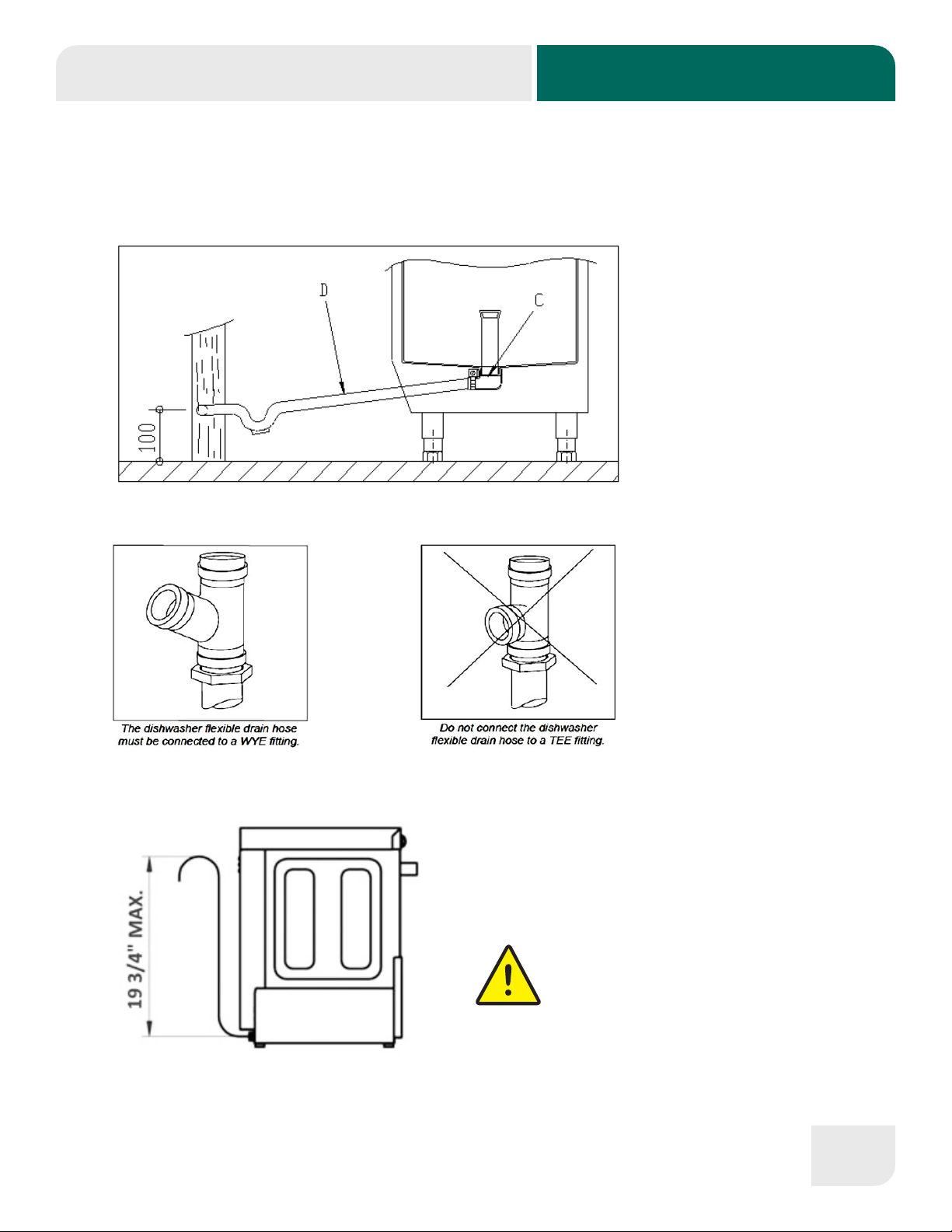
8.5 Drainage connection
Attach the drain hose as shown in Fig. 2 (on next page). The drainage pipe must always be tted on a
siphon to prevent the return of odours.
All piping from the machine to the drain must be a minimum 1-1/2” I.P.S. There should also be an air
gap between the machine drain line and the drain. For natural overow efciency use oor drain.
The water draining from the machine must ow freely and therefore the drainage pipe should be lower
than the drainage outlet (Fig. 2).
INSTALLATION INSTRUCTIONS
15
If the drainage pipe is not lower, a drainage pump will be required. This must not be mounted at a
height of more than 19 3/4” for glasswashers (Fig. 3). In this case, the pump may be requested at the
time of purchase or subsequently.
Fig. 2. Drainage installation
D: Drain hose
C: Drain collector
Fig. 3. Installation of drainage at a height using
drainage pump.
THE DRAINAGE PUMP MUST
ONLY BE INSTALLED BY
PERSONNEL AUTHORIZED BY
THE MANUFACTURER, AND THE
MANUFACTURER DOES NOT
ACCEPT LIABILITY IN THE EVENT OF
INCORRECT INSTALLATION.

INSTALLATION INSTRUCTIONS
16
8.6 Liquid rinse aid dispenser
Installation: Take the tube located in the back or your machine marked “Rinse Aid” and place inside
rinse container.
Tubes are transparent to make it visible that the chemicals are being dispensed.
Operation: This dispenser absorbs the rinse aid when it detects a loss in pressure during rinsing.
That is, when the lling solenoid valve closes, a vacuum is created that makes the rinse aid dispenser
absorb the uid to which it is connected.
Adjustment: The dispenser should be adjusted when the machine is installed to ensure that the wash
is optimized from the start. The setting should be adjusted according to the type of rinse aid and the
water hardness.
WATER PRESSURE MUST BE MINIMUM 20 PSI AT THE PRESSURE GAUGE FOR THE RINSE AID
DISPENSER TO OPERATE PROPERLY.
Rinse Aid
Filter
Regulation
Rinse Line
8.7 Detergent dispenser
This machine must be operated with an automatic detergent feeder including a visual means to verify
that detergent is delivered or a visual or audible alarm to signal if detergent is not available for delivery
to the respective washing system. Please see instructions for electrical and plumbing connections
located in this manual and in the feeder equipment manual.
The detergent dispenser ensures that the correct measure of detergent is supplied to the machine.
Use ONLY Commercial Grade, High Temperature, Low Suds Liquid Detergent. Noble doesn’t
recommend any specic brand name of chemicals. Contact your local chemical distributor for questions
concerning your chemical needs.
Installation: the detergent dispenser input is in the wash tank front part, above the maximum water
level.
Take the tube located in the back or your machine marked “Detergent” and place inside detergent
container.

INSTALLATION INSTRUCTIONS
17
Tubes are transparent to provide you visible means that chemicals are being dispensed.
Operation: the detergent dispenser is activated when the machine is taking water, whether
it is in rinse cycle or whether it is lling.
Settings: the quantity of detergent used should be adjusted on installation to ensure hat the
wash is optimized from the start.
Time-Pause Regulation
Wash Tank
Water Valve
Electrical Connection
Detergent
Filter
It is recommended that the detergent and the dispenser setting are dened by a
technician specialized in the use of chemical products in order to ensure a
more efcient wash.
If you require the installation of a NON-NOBLE Detergent and/or Rinse pump, a form
MUST be ll out prior to installation by your installer. Failure to do so will void your
Warranty. This form can be located inside your dishwasher. If lost, please contact
Noble to get a copy.
and rinse.

INSTALLATION INSTRUCTIONS
18
8.8 Recycling
The product packaging consists of:
• A wooden pallet.
• Cardboard.
• A polypropylene band.
• Expanded polyethylene.
All the packaging used around the machine can be recycled. The correct disposal of these products
will help to protect the environment. For further information regarding the recycling of these products,
please refer to your local recycling authority.

USE AND MAINTENANCE INSTRUCTIONS
19
9. USE AND MAINTENANCE INSTRUCTIONS
BEFORE STARTING THE APPLIANCE, PLEASE READ THE INSTRUCTIONS
CONTAINED IN THIS MANUAL CAREFULLY.
THE APPLIANCE IS EXCLUSIVELY FOR PROFESSIONAL USE AND SHOULD
ONLY BE USED BY QUALIFIED PERSONNEL.
9.1 Operation
The steps required to optimise the operation of your dishwasher are shown below, with all
the available options.
9.1.1 Control panel symbols
495HTGW22 (Glasswasher)
ON/OFF - LON WT RT
P1 - L1
ON/OFF ON/OFF Button
P1 Wash Cycle 1 / Drainage Button
LON ON/OFF Pilot Light
WT Wash Tub thermometer
RT Rinse boiler thermometer
L1 Blinking: Cycle pilot light
Steady: Wash tub over 150ºF
9.1.2 Switching on the machine
Before switching on the machine, check the following:
✓ The mains switch must be on.
✓ The water stop cock must be open.
✓ There must be water in the mains network.
✓ The corresponding lters must be in place.
✓ The overow should be mounted in place.
To switch on the machine just press the ON-OFF button once for 2 seconds.

USE AND MAINTENANCE INSTRUCTIONS
20
9.1.2.1 Filling and heating
In the Glasswasher model, when the machine is switched on, it will start to ll the
machine. First the rinse boiler is lled and then the wash tub. The lling process
may last a few minutes. Once the wash tub is full, the boiler and the tub start to heat
up. Although it is possible to start the wash process, this is not recommended as
the water inside the machine is not yet at the ideal temperature. When the machine
has reached the ideal temperature for washing the dishes properly, a light comes
on, advising the user that the machine is ready. The required temperature of the
machine is over 180 ºF in the rinse boiler (see thermo-stop chapter) and over 158
ºF in the wash tub. It is recommended that the water in the dishwasher is changed
every 40/50 washes or twice a day.
The machine you have purchased has a safety thermostat in the boiler and another
for the tub, so that in the event of the breakdown of any of the main thermostats, the
safety thermostats switch off the corresponding heating.
9.1.3 Hygiene practices
• Operators must strictly observe all hygiene requirements when handling clean dishes
and cutlery.
• Do not touch clean dishes with dirty or greasy hands. Handle the dishes/cutlery with
gloves or clean hands to prevent contamination. Be careful as the dishes will be hot.
• Use clean sterilized cloths to thoroughly dry the dishes. Do not dry the plates with
kitchen towels or cloths that are not sterile.
• Wait until the machine reaches the correct wash temperature to ensure a thorough
disinfection and wash. To obtain optimum results wash the dishes when the machine is
ready.
• Drain the wash tub and rinse the lters at least twice a day or every 40-50 wash cycles.
• Make sure that the quantities of detergent and rinse aid dispensed are correct (as
recommended by supplier). At the start of the work day, check that the quantity of
product in the reservoirs is enough for the daily requirement.
• The dishwasher should be kept perfectly clean and maintained.
Table of contents
Other Noble Dishwasher manuals


