Noble HT-180EC Setup guide

INSTALLATION, OPERATION,
AND SERVICE MANUAL
HT-180EC
HT-180EC Manual • 07610-004-92-22-A
NOBLE DOOR-TYPE DISHMACHINES
150 °F

ii
Revision
Letter
Revision
Date Made by Applicable ECNs Details
A 10-9-20 JH N/A Initial release of manual.
REVISION HISTORY

iii
The manufacturer provides
technical support for all of
the dishmachines detailed
in this manual. We strongly
recommend that you refer to
this manual before making a
call to our technical support
sta. Please have this manual
open when you call so that our
sta can refer you, if necessary,
to the proper page. Technical
support is not available
on holidays.
Contact technical support toll-
free at 1-888-800-5672.
Technical support is available
for service personnel only.
HT-180EC1
Door-type dishmachine; ENERGY STAR® qualied,
electric-heated, high-temp, hot-water sanitizing,
with booster heater, single-phase.
HT-180EC3
Door-type dishmachine; ENERGY STAR® qualied,
electric-heated, high-temp, hot-water sanitizing,
with booster heater, three-phase.
NOMENCLATURE

iv
TABLE OF CONTENTS
GUIDES
Symbols...................................................................................................................................... 1
Abbreviations & Acronyms.......................................................................................................... 1
SPECIFICATIONS
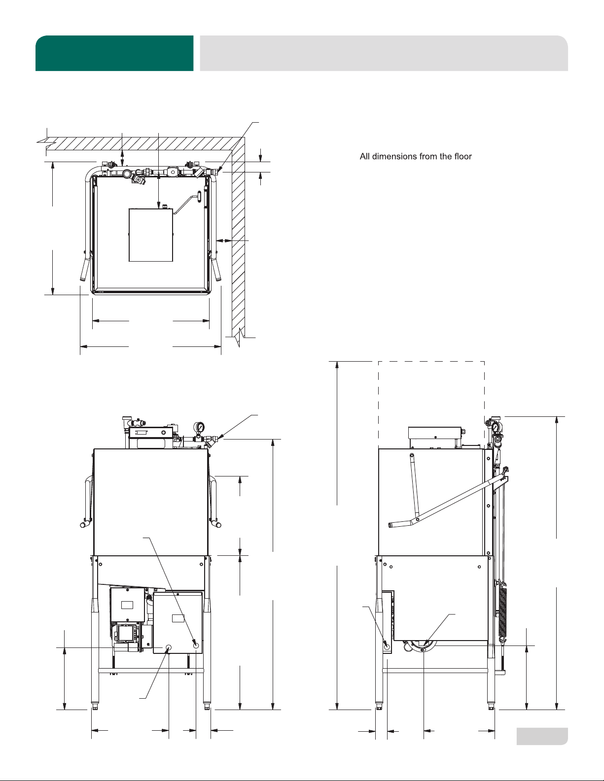
Dimensions................................................................................................................................. 2
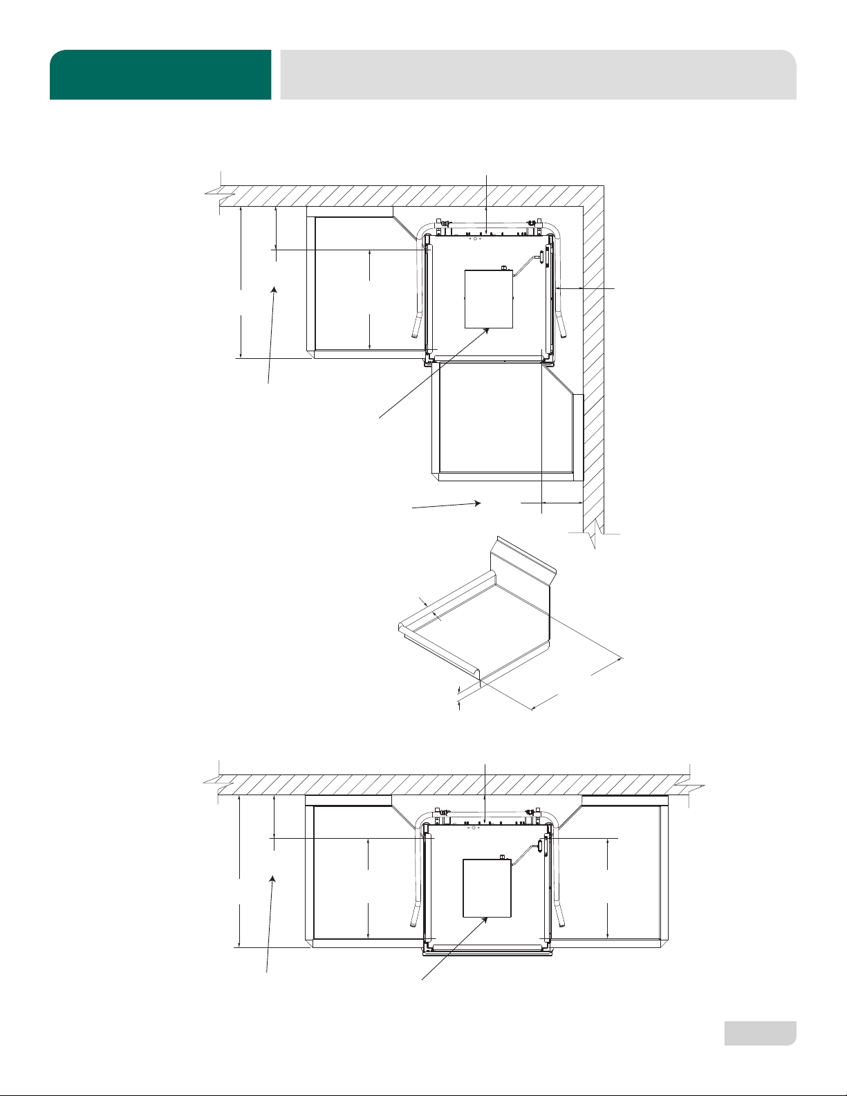
Table Dimensions ....................................................................................................................... 3
Operating Parameters ................................................................................................................ 4
Electrical Requirements ............................................................................................................. 5
INSTALLATION
Installation Instructions............................................................................................................... 6
Inspection ....................................................................................................................6
Unpacking....................................................................................................................6
Leveling .......................................................................................................................6
Plumbing......................................................................................................................6
Water Supply Connection............................................................................................6
Pressure Regulator......................................................................................................7
Shock Absorber ...........................................................................................................7
Connecting the Drain Line...........................................................................................7
Chemical & Exhaust Fan Electrical Connections ........................................................7
Chemical Connections.................................................................................................8
Plumbing Check ..........................................................................................................8
Electrical Power Connections......................................................................................9
Motor Rotation.............................................................................................................9
Voltage Check ...........................................................................................................10
Surrounding Area ......................................................................................................10
Temperature Setpoints ..............................................................................................10
OPERATION
Operating Instructions .............................................................................................................. 11
Preparation................................................................................................................ 11
Power Up................................................................................................................... 11
Filling the Wash Tub .................................................................................................. 11
Ware Preparation ...................................................................................................... 11
Daily Machine Preparation ........................................................................................ 11
Warm-Up Cycles ....................................................................................................... 12
Washing a Rack of Ware........................................................................................... 12
Operational Inspection............................................................................................... 12
Shutdown & Cleaning................................................................................................ 12

v
OPERATION
Detergent Control ..................................................................................................................... 15
Deliming ................................................................................................................................... 16
MAINTENANCE
Preventative Maintenance........................................................................................................ 17
TROUBLESHOOTING
Troubleshooting........................................................................................................................ 18
PARTS
Control Box............................................................................................................................... 20
Electrical Box............................................................................................................................ 22
Hood......................................................................................................................................... 24
Door & Arm............................................................................................................................... 26
Tub ........................................................................................................................................... 28
Frame ....................................................................................................................................... 30
Rinse Tank................................................................................................................................ 31
Motors ...................................................................................................................................... 32
Heaters..................................................................................................................................... 34
Plumbing .................................................................................................................................. 35
Plumbing Options ..................................................................................................................... 37
Wash & Rinse Assemblies........................................................................................................ 38
460 V Machine Transformer Mounting Box .............................................................................. 40
Kits ........................................................................................................................................... 41
SCHEMATICS
208/230/460 V, 50/60 Hz, 1-PH/3-PH....................................................................................... 42
TABLE OF CONTENTS

1
07610-004-92-22-A
GUIDES GUIDES
SYMBOLS
!
CAUTION
!
WARNING
NOTICE
- risk of injury to personnel.
- risk of damage to equipment.
- risk of electrical shock.
- lockout electrical power.
- reference data plate.
- important note.
i
- caustic chemicals.
ABBREVIATIONS & ACRONYMS
ANSI - American National Standards Institute
Btu/Hr - British Thermal Units per Hour
CFM - Cubic Feet per Minute
GHT - Garden Hose Thread
GPH - Gallons per Hour
GPM - Gallons per Minute
GPG - Grains per Gallon
HP - Horsepower
Hz - Hertz
ID - Inside Diameter
kW - Kilowatts
MCA - Minimum Circuit Ampacity
MOP - Maximum Overcurrent Protection
NFPA - National Fire Protection Association
NPT - National Pipe Thread
OD - Outside Diameter
PRV - Pressure Regulating Valve
PSI -Pounds per Square Inch
V- Volts

07610-004-92-22-A
2
LEGEND
A - Water Inlet (1/2” NPT)
B - Electrical Connection Point
C - Drain (1 1/2” NPT)
can be increased 1 1/8" using the
machine's adjustable feet.
8
[204 mm]
25 1/4
[641 mm]
30 5/8
[779 mm]
29
[737 mm]
59
[1499 mm]
34
[864 mm]
TABLE HEIGHT 2 1/4
[58 mm]
13 1/4
[337 mm]
3 1/4
[81 mm]
16 7/8
[428 mm]
A
B
C
15 1/2
[394 mm]
2 1/8
[55 mm]
64
[1625 mm]
76
[1930 mm]
DOOR OPEN
14
[355 mm]
C
B
17 1/4
[438 mm]
CLEARANCE
A
4
[102 mm]
MIN
4
[102 mm]
MIN
SPECIFICATIONS DIMENSIONS

07610-004-92-22-A
3
30
(762 mm)
8 7/16
(214 mm)
20 1/2”
(521 mm)
OPENING
4 (102 mm) MIN
ALIGN WITH TABLE -
DISTANCE CAN VARY
4 (102 mm) MIN
ALIGN WITH TABLE -
DISTANCE CAN VARY
8 7/16
(214 mm)
Distance from wall
to rear rack rail.
Distance from wall
to right rack rail.
Control Panel
1 1/4”
[32 mm]
1 3/8”
[35 mm]
20 1/2”
[521 mm]
OPENING
30
(762 mm)
8 7/16
(214 mm)
20 1/2”
(521 mm)
OPENING
4 (102 mm) MIN
ALIGN WITH TABLE -
DISTANCE CAN VARY
Distance from wall
to rear rack rail. Control Panel
20 1/2”
(521 mm)
OPENING
CORNER INSTALLATION
STRAIGHT-THROUGH INSTALLATION
TABLE DIMENSIONS
SPECIFICATIONS
CORNER INSTALLATION
STRAIGHT-THROUGH INSTALLATION

4
07610-004-92-22-A
PERFORMANCE/CAPABILITIES
Operating Capacity:
Racks per Hour 58
Dishes per Hour 1450
Glasses per Hour 2088
Minimum Operating Cycle (Seconds):
Wash Time 40
Rinse Time 13
Dwell Time 4
Total Cycle Time 57
Tank Capacity (Gallons/Liters):
Wash Tank 8.0/30.3
Rinse Tank 2.0/7.6
WATER REQUIREMENTS
Minimum Wash Temperature (°F/°C) 150/66
Minimum Rinse Temperature (°F/°C) 180/83
Inlet Water Temperature (°F/°C) 110/44
Flow Pressure (PSI) 10 ± 2
Water Line Size 1/2”
Drain Line Size 1 1/2”
OPERATING PARAMETERS
SPECIFICATIONS
Always refer to the machine data plate for specic electrical and water requirements. The material provided on
this page is for reference only and is subject to change without notice.
NOTICE
i

07610-004-92-22-A
5
ELECTRICAL REQUIREMENTS
SPECIFICATIONS
On three-phase machines, imbalanced wild leg goes to L3.
Also see the Motor Rotation section.
NOTICE
Local codes may require more stringent protection than what is displayed here and on the data plate. Always verify with
your electrical service contractor that your circuit protection is adequate and meets all applicable national and local codes.
Numbers in this manual are for reference and may change without notice.
Volts Phase Freq Wash
Motor
Wash
Heater
Rinse
Heater Total Load MCA MOP
208 1 60 Hz 5.0 A 19.7 A 50.6 A 75.3 A 76.6 A 80.0 A
230 1 60 Hz 5.0 A 21.8 A 55.9 A 82.7 A 84.0 A 90.0 A
208 3 60 Hz 5.0 A 11.4 A 29.2 A 45.6 A 46.9 A 50.0 A
230 3 60 Hz 5.0 A 12.6 A 32.3 A 49.9 A 51.2 A 55.0 A
i

07610-004-92-22-A
6
INSTRUCTIONS
INSTALLATION
Before installing the machine, check the packaging and machine for damage. If the
packaging is damaged, the machine might also be damaged. If there is damage to both
packaging and machine, do not throw away the packaging. The machine has been
inspected and packed at the factory and is expected to arrive to you in new, undamaged
condition. However, rough handling by carriers or others might result in damage to the
machine while in transit. If so, do not return the machine to the manufacturer. Instead,
contact the carrier and ask them to send a representative to the site to inspect the
damage and complete an inspection report. You must contact the carrier and the dealer
that sold you the machine within 48 hours of receiving the machine.
While unpacking the machine, ensure that there are no missing parts. If an item is
missing, contact the manufacturer immediately.
The machine must be level in its operating location to prevent damage to the machine
during operation and to ensure the best results. The machine comes with four adjustable
bullet feet, which can be turned using a pair of channel locks (or by hand if the machine
can be raised safely). Ensure that the machine is level from side-to-side and front-to-
back before making any connections.
Plumbing connections must comply with all applicable local, state, and national
plumbing codes. The plumber is responsible for ensuring that the incoming water line
is thoroughly ushed before connecting it to any component of the machine. It is very
important to remove all foreign debris from the water line that might potentially get
trapped in the valves or cause an obstruction. Any valves that are fouled as a result of
foreign matter left in the water line—and any expenses resulting from this fouling—are
not the responsibility of the manufacturer.
A water hardness test must be performed to determine if a water treatment system
needs to be installed.
If water hardness tests at greater than 3 GPG, install the Scaltrol Water Treatment
system (see the Plumbing Options page) into the water line before the machine’s
incoming water connection point. A water shut-o valve should be installed to allow
access for service.
If water hardness tests at lower than 3 GPG, install the water supply line directly to
the machine’s incoming water connection point. A water shut-o valve should be
installed to allow access for service.
INSPECTION
LEVELING
UNPACKING
PLUMBING
A water hardness test
MUST be performed.
Do not throw away
packaging if damage is
evident!
WATER SUPPLY
CONNECTION:
WATER HARDNESS
GREATER THAN
3 GPG
WATER SUPPLY
CONNECTION:
WATER HARDNESS
LOWER THAN 3 GPG
The plumber MUST ush
the incoming water line!

7
07610-004-92-22-A
INSTRUCTIONS
INSTALLATION
PRESSURE
REGULATOR
SHOCK ABSORBER
CONNECTING THE
DRAIN LINE
The manufacturer recommends the installation of a pressure regulating valve (PRV)
in the incoming water line to ensure proper owrate at all times and oers these
devices as options (see the Plumbing Options page).
Do not confuse static pressure with ow pressure. Static pressure is the line pressure
in a “no ow” condition (all valves and services are closed). Flow pressure is the
pressure in the ll line when the ll valve is opened during the cycle.
The manufacturer also recommends the installation of a shock absorber in the
incoming water line and oers these devices as options (see the Plumbing Options
page). This prevents line hammer/hydraulic shock—induced by the solenoid valve as
it operates—from causing damage to the equipment.
The machine's drain is a gravity-discharge drain. All piping from the 1 1/2” NPT
connection on the wash tank must be pitched (1/4” per foot) to the oor or sink drain.
All piping from the machine to the drain must be a minimum 1 1/2” NPT and must not
be reduced. There must also be an air-gap between the machine drain line and the
oor sink or drain. If a grease trap is required by code, it should have a ow capacity
of 5 GPM.
Remove control box lid and make chemical and exhaust fan connections at the
points shown below:
CHEMICAL &
EXHAUST FAN
ELECTRICAL
CONNECTIONS
EXHAUST FAN
CONTROL
CONNECTION
EXHAUST FAN
CONTROL
CONNECTION
RINSE AID
DISPENSER
CONNECTION
DETERGENT
DISPENSER
CONNECTION
CONSTANT
VOLTAGE
CONNECTION
L1 TO EXHAUST
FAN CONTACTOR
COIL
3 AMP SLOW BLOW
FUSE
CUSTOMER
EXTERNAL VOLTAGE
SOURCE FOR FAN
CONTACTOR COIL,
240V MAX
3 AMP SLOW BLOW
FUSE
L1 208-240V
OUTPUT
LIVE WHEN RINSE
VALVE IS OPEN
3 AMP SLOW BLOW
FUSE
L1 208-240V
OUTPUT
LIVE WHEN WASH
PUMP IS ON
3 AMP SLOW BLOW
FUSE
L1 208-240V
OUTPUT
LIVE WHEN MACHINE
POWER IS ON
3 AMP SLOW BLOW
FUSE
F2 F3 F4 F5 F6
L2 (TO CHEMICAL
DISPENSERS)

07610-004-92-22-A
8
INSTRUCTIONS
INSTALLATION
CHEMICAL
CONNECTIONS
PLUMBING CHECK Slowly turn on the water supply to the machine after the incoming ll line and drain
line have been installed. Check for any leaks and repair as required. All leaks must be
repaired before operating the machine.
Detergent
Connect detergent by removing the bulkhead tting on the back of the machine and
replacing it with the appropriate dispensing equipment.
Chemical connections
should be made by the
chemical supplier.
Rinse-aid
Connect rinse-aid by removing the brass plug at the base of the rinse injector and
replacing it with the appropriate dispensing equipment.
Rinse-aid
Using deionized water or
other aggressive uids
will result in corrosion and
failure of components and
will void the warranty.
WARNING! Some of the
chemicals used in
dishwashing may cause
chemical burns if they
come in contact with skin.
Wear protective gear when
handling these chemicals.
If any skin comes in
contact with these
chemicals, immediately
follow the instructions
provided with the
chemicals for treatment.
!
WARNING
Detergent Probe
Installs Here

9
07610-004-92-22-A
INSTRUCTIONS
INSTALLATION
Electrical and grounding conductors must comply with the applicable portions of the
National Electric Code ANSI/NFPA 70 (latest edition) and/or other electrical codes.
The data plate is located on the right side of the machine. Refer to the data plate for
machine operating requirements, machine voltage, total amperage, and serial number.
1. Open electrical box at bottom-front of machine by using a phillips screwdriver to
remove the two screws.
2. Install 3/4” conduit into the pre-punched hole in bottom of electrical box.
3. Route power wires and connect to power block and grounding lug.
4. Install service wires (L3 for 3-Phase only) to the appropriate terminal.
5. Install the grounding wire into the lug provided.
6. Tighten the connections.
“DE-OX” or similar anti-oxidation agent should be used on all power
connections.
On 460 V 3-Phase machines only, correct pump motor rotation must be veried
before the machine is operated. Failure to do so can result in damage to the
machine and components.
1. Follow the "Filling the Wash Tub" section.
2. Locate the wash pump motor and identify the arrow decal which shows the
correct motor rotation (if no decal is present, correct rotation is away from the
pump volute).
3. Start the machine.
4. Observe the rotation of motor fan and quickly stop the machine.
5. If rotation is incorrect, disconnect electrical power and reverse the L1 and L2
connections at terminal block shown in the section above.
ELECTRICAL POWER
CONNECTIONS
Disconnect electrical
power supplies and
lockout/tagout in
accordance with
appropriate procedures
and codes at the
disconnect switch.
MOTOR ROTATION
i
Imbalanced
wild leg goes
to L3.
NOTICE
NOTICE
CAUTION! On 460 V
3-Phase machines only,
correct pump motor
rotation must be veried
before operation!
!
CAUTION
If necessary, see
"Heaters" page for
phase conversion kit.
Pump Volute
Motor Fan
3Φ

07610-004-92-22-A
10
INSTRUCTIONS
INSTALLATION
Apply power to machine. Check the incoming power at the terminal block and
ensure it corresponds with the voltage listed on the data plate. If not, contact a
qualied service agency to examine the problem. Do not run the machine if voltage
is too high or too low. Shut o the service breaker and advise all proper personnel
of the location of the breaker and any problems. Replace the control box cover and
tighten-down the screws.
This is a commercial dishmachine and reaches temperatures that can exceed those
generated by a residential machine. Surrounding countertops, cabinets, ooring mate-
rial, and subooring material must be designed and/or selected with these higher
temperatures in mind.
Any damage to surrounding area caused by heat/moisture to materials that
are not recommended for higher temperatures will not be covered under
warranty or by the manufacturer.
The temperature setpoints on this machine have been set at the factory. They
should only be adjusted by an authorized service agent.
TEMPERATURE
SETPOINTS
SURROUNDING
AREA
NOTICE
VOLTAGE CHECK
i

11
07610-004-92-22-A
OPERATING INSTRUCTIONS
OPERATION
Before operating the machine, verify the following:
1. Tank is clean and free of debris.
2. Wash arms, rinse arms, and scrap screen are installed correctly.
3. Sump strainer and standpipe (located under scrap screen) are installed correctly
and standpipe is down.
To energize the machine, turn on the power at the service breaker. The voltage should
have been previously veried as being correct. If not, the voltage will have to be
veried.
1. Close door.
2. Press power button.
3. LED ring on power button will turn red.
4. Machine will start filling automatically.
5. Wait until wash temperature on display reaches a minimum of 150 °F.
Proper ware preparation will help ensure good results and fewer re-washes. If not
prepared properly, ware might not come out clean and the eciency of the machine
will be reduced. Putting unscraped dishes into the machine aects its performance,
so scraps should always be removed from ware before being loaded into a rack.
Pre-rinsing and pre-soaking are good ideas, especially for silverware and casserole
dishes.
Place cups and glasses upside-down in racks so they don't hold water during the
cycle. The machine sanitizes as well as cleans. To do this, ware must be properly
prepared before being placed in the machine.
Refer to the “Preparation” section and follow the instructions there. Afterward, ensure
that chemicals are supplied to the machine. If not, contact your
chemical supplier.
PREPARATION
POWER UP
WARE
PREPARATION
FILLING THE
WASH TUB
DAILY MACHINE
PREPARATION
Standpipe
Wash & Rinse Arms, Scrap Screen Sump Strainer
150 °F

07610-004-92-22-A
12
1. Ensure wash temperature has reached a minimum of 150 °F.
2. Open door completely.
3. Slide rack of ware into the machine.
4. Close door and cycle starts automatically. LED ring on power button will turn
green.
5. When LED ring on power button turns red, cycle is complete.
6. Open door and remove rack of clean ware.
7. Replace with a rack of soiled ware and close door. Repeat this process.
Based on use, the scrap screen might become clogged with soil and debris as the
workday progresses. Operators should regularly inspect the scrap screen to ensure
it has not become clogged. If clogged, it will reduce the washing capability of the
machine. Instruct operators to clean-out the scrap screen at regular intervals or as
required by workload. Do NOT beat strainers to remove debris.
1. Turn machine off by pushing power button. Display and LED will turn off.
2. Open door and allow steam/heat to escape.
3. Raise standpipe and allow tub to drain.
OPERATING INSTRUCTIONS
OPERATION
WASHING A RACK OF
WARE
OPERATIONAL
INSPECTION
SHUTDOWN &
CLEANING
!
WARNING
WARNING! Wash tank
water will be hot!
150 °F

13
07610-004-92-22-A
OPERATING INSTRUCTIONS
OPERATION
4. Remove sump strainer and scrap screen.
5. Use a hand-scraper to scrape foodsoil into a trash basket.
6. Rinse with pre-rinse hose and replace.
7. Remove all wash and rinse arms.
8. Remove the end-caps from the arms.
9. Clean nozzles with a brush.
10. Use a small wire or toothpick to remove remaining debris or lime deposits from
the nozzles.
11. Flush the arms with water.
SHUTDOWN &
CLEANING

07610-004-92-22-A
14
OPERATING INSTRUCTIONS
OPERATION
12. Replace end-caps and ensure they have been tightened.
13. Spray or wipe out interior of the machine.
14. Replace wash and rinse arms.
15. Ensure sump strainer and scrap screen are clean and securely in place.
16. Use stainless steel polish to clean and protect outside of the machine.
SHUTDOWN &
CLEANING

15
07610-004-92-22-A
DETERGENT CONTROL
OPERATION
Detergent usage and water hardness are two factors that contribute greatly to how
eciently this machine will operate. Using detergent in the proper amount can
become a source of substantial savings. A qualied water treatment specialist can
determine what is needed for maximum eciency from the detergent.
1. Hard water greatly aects the performance of the machine, causing the amount
of detergent required for washing to increase. If the machine is installed in an
area with hard water, the manufacturer recommends the installation of water
treatment equipment.
2. Deposited solids from hard water can cause spotting that will not be removed
with a drying agent. Treated water will reduce this occurence.
3. Treated water might not be suitable for use in other areas of operation and it
might be necessary to install a water treatment system for the water going to the
machine only. Discuss this option with a qualied water treatment specialist.
4. Machine operators should be properly trained on how much detergent is to be
used per cycle. Meet with a water treatment specialist and detergent vendor to
discuss a complete training program for operators.
5. These machines require that chemicals be provided for proper operation and
sanitization and require the installation of third-party chemical feeders to
introduce these chemicals to the machine. Contact a chemical supplier with any
questions.
6. Water temperature is an important factor in ensuring that the machine functions
properly. The machine's data plate details what the minimum temperatures must
be for the incoming water supply, the wash tank, and the rinse tank. If minimum
requirements are not met, there is a possibility that dishes will not be clean or
sanitized.
7. Instruct machine operators to observe the required temperatures and to report
when they fall below the minimum allowed. A loss of temperature can indicate a
larger problem.
DETERGENT
CONTROL
i
See "Water Supply
Connection" section for
more information
on water treatment.
This manual suits for next models
2
Table of contents
Other Noble Dishwasher manuals