Noble DG-E Manual

INSTALLATION, OPERATION
& SERVICE MANUAL
FOR NOBLE MODELS:
NOBLE DG-E
NOBLE DG-D
NOBLE CHEMICAL SANITIZING DISHMACHINE
July, 2015
P/N 07610-004-24-94
Noble Warewashing
Lancaster, Pennsylvania
www.nobleproducts.biz


REVISION/
PAGE
REVISION
DATE
MADE
BY
APPLICABLE
ECN DETAILS
A 07-15-15 KAP N/A Release to production.
i

ii
NOMENCLATURE FOR THE MODELS COVERED IN THIS MANUAL
NOBLE DG-E
DG-E - Low temperature, chemically sanitizing, with a booster tank.
Detergent, rinse aid & sanitizer chemical feeder pumps
DG-D - Dual door. Low temperature, chemically sanitizing, with a booster tank.
Detergent, rinse aid & sanitizer chemmical feeder pumps
Model:
Serial No.:
Installation Date:
Service Rep. Name:
Phone No.:

SECTION DESCRIPTION PAGE
I.
2
3
II.
5
6
7
9
SPECIFICATION INFORMATION
Specifications
Dimensions
INSTALLATION/OPERATION INSTRUCTIONS
Installation Instructions
Electrical Installation Instructions
Operation Instructions
Chemical Dispensing Equipment
Detergent Control
Electronic Cycle Timer
10
III. PREVENTATIVE MAINTENANCE 15
IV. TROUBLESHOOTING SECTION
Common Problems 17
V. PARTS SECTION
Chemical Feeder Pump Assembly 21
Solenoid Valve Repair Parts 22
Control Box Assembly 25
Peripump Box Assembly 26
Electrical Connection Box Assembly 27
Frame Assembly 28
Hood Assembly 29
Switch Panel Assembly 30
Tub Assembly 32
Frame & Motor Assembly 34
Pump and Motor Assembly 35
Booster Tank Assembly 36
Incoming Plumbing Assembly 37
Door Components 38
Front Panel Assembly 39
VI. ELECTRICAL SCHEMATICS
NOBLE DG-E (prior to serial # 14A288762) 41
NOBLE DG-E (after serial # 14A288762) 42
NOBLE DG-E schematics 43
NOBLE DG-E Harness Connections 44
TABLE OF CONTENTS
iii
11

1
SECTION 1:
SPECIFICATION INFORMATION

SECTION 1: SPECIFICATION INFORMATION
SPECIFICATIONS OF THE NOBLE DG-E
2
OPERATING CAPACITY ( NSF RATED):
RACKS PER HOUR 29
DISHES PER HOUR 725
GLASSES PER HOUR 1,044
OPERATING CYCLES (SECONDS):
NORMAL CYCLE:
WASH TIME 45
RINSE TIME 25
TOTAL CYCLE TIME 90
WASH TANK CAPACITY (GALLONS): 1.2
WASH PUMP CAPACITY (GPM): 61
OPERATING TEMPERATURES:
WASH (MINIMUM) (48.9°C) 120°F
WASH (RECOMMENDED) (60.0°C) 140°F
RINSE (MINIMUM) (48.9°C) 120°F
RINSE (RECOMMENDED) (60.0°C) 140°F
WATER REQUIREMENTS:
WATER LINE SIZE NPT 1/2”
DRAIN LINE SIZE NPT 2”
FLOW PRESSURE 20 ±5 PSI
MINIMUM CHLORINE REQUIRED (PPM): 50
ELECTRICAL REQUIREMENTS:
WASH PUMP MOTOR HP 3/4
RINSE TYPICAL
HEATER TOTAL ELECTRICAL
VOLTS PH HZ RATINGS AMPS CIRCUIT
115 1 60 2KW@110V *16 A 20 AMP
* This dishmachine is designed so that the wash motor is never
running when the wash heater is on. Service load is based upon
the higher of the two amperages.
NOTE: Typical Electrical Circuit is based upon (1) 125% of the
full amperage load of the machine and (2) typical fixed-trip
circuit breaker sizes as listed in the NEC 2002 Edition. Local
codes may require more stringent protection than what is
displayed here. Always verify with an electrical service
contractor that the circuit protection is adequate and meets
all applicable national and local codes. These numbers are
provided in this manual simply for reference and may change
without notice at any given time.
FRAME DIMENSIONS:
WIDTH (622.3mm) 24 1/2”
DEPTH (641.35mm) 25 1/4”
DEPTH, WITH FRONT DOOR OPEN (933.45mm) 36 3/4”
HEIGHT (990.6mm) 39”
MAXIMUM WASH
CHAMBER CLEARANCE (292.1mm) 11 1/2”
FRAME DIMENSION (DOUBLE DOOR):
WIDTH (622.3MM) 24 1/2”
DEPTH (714.375MM) 28 1/8”
DEPTH, WITH DOOR OPEN (1311.275MM) 51 5/8”
HEIGHT (990.6MM) 39”
CHAMBER CLEARANCE (292.1MM) 11 1/2”
NOTE: Always refer to the machine data plate for specific
electrical and water requirements. The material provided on
this page is for reference only and may be subject to change
without notice.
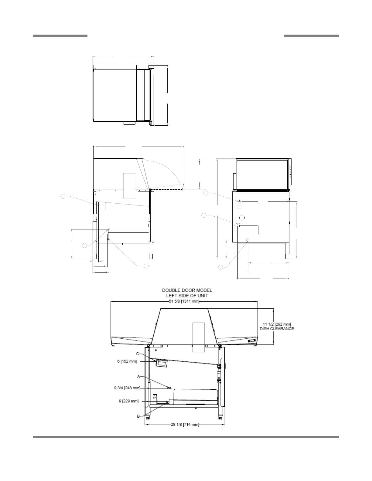
SECTION 1: SPECIFICATION INFORMATION
MACHINE DIMENSIONS
3
21 1/4
(540 mm)
17
(432 mm)
20
(508 mm)
C
A
21 1/4
(540 mm)
B
7 3/4
(197 mm)
39
(991 mm)
6 3/4 (171 mm)
6 (152 mm)
12 1/4
(311 mm)
36 3/4
(933 mm)
24 1/2
(622 mm)
25 1/4
(642 mm)
C
A
B
3 (76 mm)
A - Incoming Water Connection
B - Drain Connection - 2" IPS
C - Electrical Connection Point
NOTE: All vertical dimensions are
at lowest point due to adjustable
bullet feet and may be raised an
additional 2 3/4".
11 1/2
(292 mm)
DISH
CLEARANCE

4
SECTION 2:
INSTALLATION & OPERATION INSTRUCTIONS

INSTALLATION INSTRUCTIONS
5
SECTION 2: INSTALLATION & OPERATION INSTRUCTIONS
VISUAL INSPECTION: Before installing unit check container and machine for damage. A damaged container may be an
indication of damage to the machine. If there is any type of damage to both container and unit, do not throw away the container.
The dishmachine has been inspected at the factory prior to shipping and is expected to arrive in new, undamaged condition.
However, rough handling by carriers or others may result in damage to the unit while it is in transit. If such a situation occurs,
do not return the unit to the manufacturer. Instead, contact the carrier and ask them to send a representative to the site to
inspect the damage, and request that an inspection report be completed. Contact the carrier within 48 hours of receiving the
machine (to report possible freight damage) and the dealer from whom the unit was purchased.
UNPACKING THE DISHMACHINE: Remove the machine from the container and inspect it for any missing parts. If a part is
missing, contact manufacturer immediately.
LEVEL THE DISHMACHINE: The dishmachine is designed to operate while level. This is important to
prevent any damage to the machine during operation and to ensure the best results possible. The unit
is equipped with adjustable bullet feet which can be turned using a pair of pliers. Verify the unit is level
from front to back and side to side before making any electrical or plumbing connections.
PLUMBING THE DISHMACHINE:All plumbing connections must be made to adhere to local, state,
territorial and national codes. The installing plumber is responsible for ensuring the incoming water lines are flushed of debris
prior to connecting to the machine. Note that chips and materials from cutting processes can become lodged in the solenoid
valves and prevent them from opening or closing. Any valves that are found to be fouled or defective because of foreign
matter left in the water line, and any subsequent water damage, are not the responsibility of the manufacturer.
A water hardness test should be performed to determine if the HTS-11 (scale prevention & corrosion control) needs to be
installed. If water hardness is higher than 5 GPG, the HTS-11 will need to be installed. Please contact manufacturer to purchase
the HTS-11.
CONNECTING THE DRAIN LINE: This dishmachine drain requires a minimum 2” NPT piping that
is pitched at least 1/4” per foot. There must also be an air gap between the machine drain line and
the floor sink or drain. If a grease trap is required by code, it should have a flow capacity of
5 gallons per minute.
WATER SUPPLY CONNECTION: Install the water supply line (1/2” NPT minimum) to the dishmachine
line y-strainer using copper pipe. It is recommended that a water shut-off valve be installed between
the main supply and the machine to allow for service. The water supply line must be capable of 20 ±5
PSI “flow” pressure at the recommended temperature as indicated on the data plate.
PRESSURE REGULATOR: In areas where the water pressure fluctuates or is greater than the
recommended pressure, it is suggested that a water pressure regulator be installed. This dishmachine
does not come with a water pressure regulator as standard equipment.
SHOCK ABSORBER: It is recommended that a shock absorber (not supplied) be installed in the
incoming water line. This prevents water hammer (hydraulic shock)—induced by the solenoid valve as
it operates—from causing damage to the equipment.
PLUMBING CHECK: Slowly turn on the water supply to the machine after connecting the incoming fill line and drain line.
Check for leaks and repair as required. Leaks must be repaired prior to operating the machine.
Frame with Adjustable Foot
Drain Connection
Y-Strainer
Raise Lower
This manual suits for next models
1
Table of contents
Other Noble Dishwasher manuals


