Noble HT-180 HH Setup guide

INSTALLATION, OPERATION,
AND SERVICE MANUAL
HT-180 HH
SERIES
HT-180 HH Series Manual • 07610-003-26-29-H
NOBLE DOOR-TYPE DISHMACHINES

REVISION HISTORY
Revision
Letter
Revision
Date Made by Applicable
ECNs Details
A 7-24-15 KAP N/A Release to production.
B 10-8-15 KAP N/A Added HH ventless booster tank assembly on pg. 40.
C 11-10-15 JH N/A Corrected P/N for item #40 on pg. 37.
D 11-23-15 JH QOF-386 Replaced Plumbing Booster Inlet diagram, pg. 50.
E 1-12-16 JH
QOF-386
N/A
N/A
Changed item #12 on pg. 36 to 05700-003-07-76.
Added 05700-004-23-78, 05700-004-23-79, and 05700-004-23-
80 to view (pg. 35) and parts list (pg. 36).
Corrected Typical Electrical Circuits for HT-180HH Ventless.
F 5-11-17 JH N/A
Removed views that showed pressure regulator in certain
locations. Added the pressure regulator as an option.
Added exploded view and parts list for Motor & Pump Assembly.
Changed name of delime switch throughout from NORMAL/
DELIME to AUTO/MANUAL.
Added instructions on rinse arm maintenance to the
Maintenance section.
Added dimensions for the corner table notch to the Table
Dimensions page.
Added a Plumbing Options page.
Added the dispenser connections decal for the 460 V machine.
Added instructional pictures where appropriate.
Added external device wiring instructions as an Addendum.
Added instructions for programming new exhaust fan timer.
Updated schematics.
Updated to new manual format.
Audited and corrected all P/Ns in the manual.
G 9-11-17 JH 8541
8543
Moved door switch from the Tub Assembly page to the Hood
Assembly page.
Added door switch bracket assembly to the Hood Assembly
page.
Updated schematics.
H 10-23-18 JH
8392
8533
8536
8558
8567
8576
8599
Updated pg. 4.
Changed steam pressure to 10-30 PSI on pg. 5.
Updated electrical requirements on pgs. 6-7.
Added links to exhaust fan timer instructions to pg. 9.
Added Chemical Connections section to pg. 10.
Added Motor Rotation section to pg. 11.
Added False Panel/Corner Install section to pg. 12.
Added new exhaust fan timer to pgs. 23 and 25.
Changed P/N for contactor, item #4 on pg. 24.
Updated pgs. 28-29 with new door and arm assembly.
Replaced thermostat and components with solid state thermostat
and components pgs. 30-34.
Added phase conversion kit P/Ns to pg. 41.
Changed rinse arm bearing assembly on pgs. 52-53.
Changed rinse arm bearing kit P/N on pg. 53.
Added list of applicable kits to pg. 59.
Updated schematics.

The manufacturer provides
technical support for all of
the machines detailed in
this manual. We strongly
recommend that you refer to
this manual before making a
call to our technical support
sta. Please have this manual
open when you call so that our
sta can refer you, if necessary,
to the proper page. Technical
support is not available on
holidays.
Contact technical support toll
free at 1-888-800-5672.
Technical support is available
for service personnel only.
NOMENCLATURE
HT-180 HH
Door-type dishmachine; electrically-heated, high-temp, hot-water sanitizing,
with booster heater.
HT-180 HH NB
Door-type dishmachine; electrically-heated, high-temp, hot-water sanitizing,
no rinse booster.
HT-180 HH S
Door-type dishmachine; steam-heated, high-temp, hot-water sanitizing.
HT-180 HH VER
Door-type dishmachine; electrically-heated, high-temp, hot-water sanitizing,
with booster heater and ventless energy recovery system.

v
GUIDES
Symbols......................................................................................................................................... 1
Abbreviations & Acronyms ............................................................................................................ 1
SPECIFICATIONS
Dimensions.................................................................................................................................... 2
Dimensions - HH VER................................................................................................................... 3
Table Dimensions .......................................................................................................................... 4
Operating Parameters ................................................................................................................... 5
Electrical Requirements ................................................................................................................ 6
INSTALLATION
Installation Instructions.................................................................................................................. 8
Inspection......................................................................................................................... 8
Unpacking........................................................................................................................ 8
HH VER Assembly........................................................................................................... 8
Leveling............................................................................................................................ 8
Plumbing.......................................................................................................................... 8
Water Supply Connection ................................................................................................ 8
Steam Line Connection.................................................................................................... 9
Pressure Regulator.......................................................................................................... 9
Shock Absorber ............................................................................................................... 9
Connecting the Drain Line ............................................................................................... 9
Exhaust Fan Timer........................................................................................................... 9
Chemical Connections................................................................................................... 10
Plumbing Check............................................................................................................. 10
Electrical Power Connections .........................................................................................11
Motor Rotation ................................................................................................................11
Voltage Check................................................................................................................ 12
Surrounding Area........................................................................................................... 12
Temperature Setpoints................................................................................................... 12
False Panel/Corner Install.............................................................................................. 12
Facility Hot Water Heater............................................................................................... 12
TABLE OF CONTENTS

vi
OPERATION
Operating Instructions ................................................................................................................. 13
Preparation..................................................................................................................... 13
Power Up........................................................................................................................ 13
Filling the Wash Tub ....................................................................................................... 13
Ware Preparation ........................................................................................................... 13
Daily Machine Preparation ............................................................................................. 13
Warm-up Cycles ............................................................................................................. 14
Washing a Rack of Ware................................................................................................ 14
Operational Inspection.................................................................................................... 14
Shutdown & Cleaning..................................................................................................... 14
VER Coil Cleaning.......................................................................................................... 16
Detergent Control ........................................................................................................... 17
Deliming.......................................................................................................................... 18
MAINTENANCE
Preventative Maintenance........................................................................................................... 19
TROUBLESHOOTING
Common Problems...................................................................................................................... 20
PARTS
Control Box.................................................................................................................................. 22
Hood............................................................................................................................................ 26
Door & Arm.................................................................................................................................. 28
Tub .............................................................................................................................................. 30
Steam Tub ................................................................................................................................... 33
Frame .......................................................................................................................................... 35
Rinse Tank .................................................................................................................................. 36
VER Rinse Tank ......................................................................................................................... 37
Steam Coil .................................................................................................................................. 38
Motors ......................................................................................................................................... 39
Heaters........................................................................................................................................ 41
Inlet Plumbing - HH ..................................................................................................................... 42
Outlet Plumbing - HH .................................................................................................................. 44
Plumbing - HH VER ................................................................................................................46
Inlet Plumbing - HH S ................................................................................................................. 48
Outlet Plumbing - HH S .............................................................................................................. 49
TABLE OF CONTENTS

vii
PARTS
Plumbing Options ....................................................................................................................... 50
Solenoid Valve & Vacuum Breaker Parts .................................................................................... 51
Wash & Rinse Assemblies........................................................................................................... 52
VER System ................................................................................................................................ 54
VER System Door Interlock......................................................................................................... 56
VER System Door Interlock Override.......................................................................................... 57
460 V Machine Transformer Mounting Box ................................................................................. 58
Kits .............................................................................................................................................. 59
SCHEMATICS
HH/HH VER 208/230 V ............................................................................................................... 60
HH/HH VER 460 V ...................................................................................................................... 61
HH NB 208/230 V........................................................................................................................ 62
HH NB 460 V............................................................................................................................... 63
HH S 208/230 V .......................................................................................................................... 64
SDI Options ................................................................................................................................. 65
TABLE OF CONTENTS
1
07610-004-26-29-H
GUIDES GUIDES
SYMBOLS
!
CAUTION
!
WARNING
NOTICE
- risk of injury to personnel.
- risk of damage to equipment.
- risk of electrical shock.
- lockout electrical power.
- reference data plate.
- important note.
i
- caustic chemicals.
ABBREVIATIONS & ACRONYMS
- instructions hyperlink.
ANSI - American National Standards Institute
Btu/Hr - British Thermal Units per Hour
CFM - Cubic Feet per Minute
GHT - Garden Hose Thread
GPH - Gallons per Hour
GPM - Gallons per Minute
GPG - Grains per Gallon
HP - Horsepower
Hz - Hertz
ID - Inside Diameter
kW - Kilowatts
MCA - Minimum Circuit Ampacity
MOP - Maximum Overcurrent Protection
NFPA - National Fire Protection Association
NPT - National Pipe Thread
OD - Outside Diameter
PRV - Pressure Regulating Valve
PSI -Pounds per Square Inch
V- Volts
07610-004-26-29-H
2
25
14
[641 mm]
C
31 [803 mm]
3
78
[97 mm] 1
[25 mm]
B
C
34
[864 mm]
11
34
[299 mm]
A
6812
[1740 mm]
7638
[1941mm]
25
14
[641 mm]
73
34
[1874 mm]
27
[686 mm]
CLEARANCE
86
34
[2203 mm]
WITH DOOR
OPEN
A
73
[1854 mm]
17 [432 mm]
C
B
28
58
[727 mm]
25 [635 mm]
14
15 [387 mm]
LEGEND
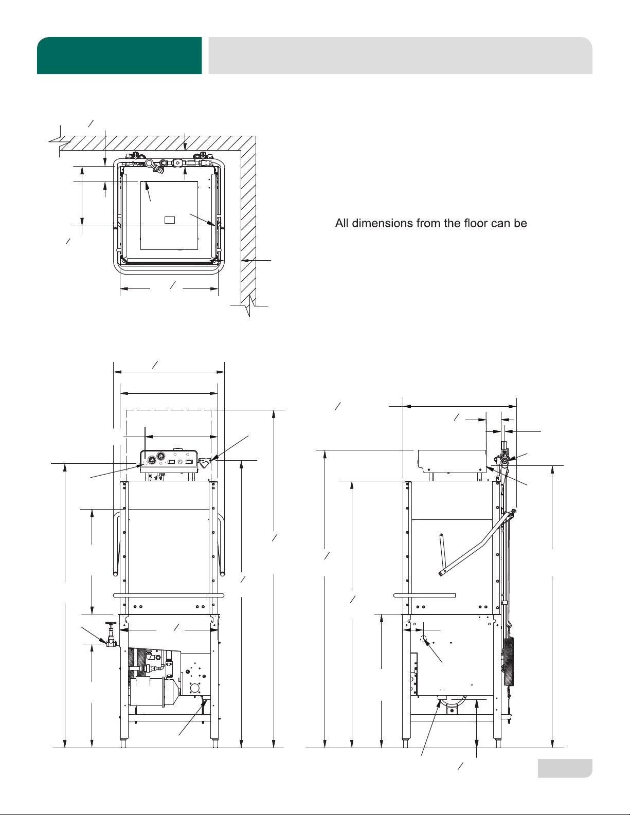
A - Drain 1 1/2" NPT
B - Water Inlet 3/4" NPT
C - Electrical Connection
increased 2" using the machine's
adjustable feet.
73
[1856mm]
4
[102 mm]
MINIMUM
4 [124 mm]
78
58
A
4
[102 mm]
MINIMUM
20
[508 mm]
D
D
5 1/2
(140 mm)
D - Optional Steam Connection 3/4” NPT
DIMENSIONS
SPECIFICATIONS
3
07610-004-26-29-H
( 3 mm)
23
4(79mm)
151
4(387mm)
113
4(298mm)
17 (432mm)
2 ( 7mm)
73 (1856mm)
34 (861mm)
93 (2362mm)
B
88 (2235mm)
C
10mm
51
4(134mm)
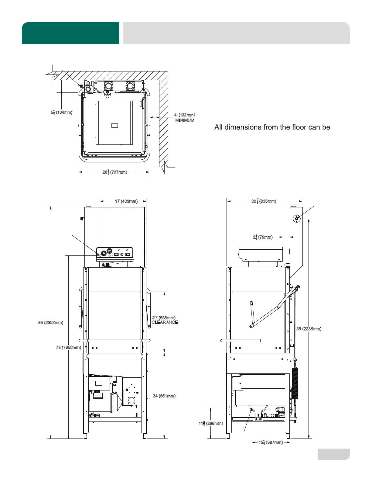
LEGEND
A - Drain 1 1/2" NPT
B - Water Inlet 3/4" NPT
C - Electrical Connection
increased 2" using the machine's
adjustable feet.
4(
(
2
85
872
7 ( mm)
CLEARANCE
2668
8
7
325
8
A
B
MINIMUM
DIMENSIONS - HH VER
SPECIFICATIONS

07610-004-26-29-H
4
TABLE DIMENSIONS
SPECIFICATIONS
30
(762 mm)
8 1/4
(210 mm)
20 1/2”
(521 mm)
OPENING
4 (102 mm) MIN
ALIGN WITH TABLE -
DISTANCE CAN VARY
4 (102 mm) MIN
ALIGN WITH TABLE -
DISTANCE CAN VARY
8 1/4
(210 mm)
Distance from wall
to rear rack rail.
Distance from wall
to right rack rail.
Control Panel
1 1/4”
[32 mm]
1 3/8”
[35 mm]
20 1/2”
[521 mm]
OPENING
30
(762 mm)
8 1/4
(210 mm)
20 1/2”
(521 mm)
OPENING
4 (102 mm) MIN
ALIGN WITH TABLE -
DISTANCE CAN VARY
Distance from wall
to rear rack rail. Control Panel
20 1/2”
(521 mm)
OPENING
For corner
install instructions:
CORNER INSTALLATION
STRAIGHT-THROUGH INSTALLATION

5
07610-004-26-29-H
OPERATING PARAMETERS
SPECIFICATIONS
OPERATING CAPACITY:
Normal Cycle
Racks per Hour 53
Dishes per Hour 1325
Glasses per Hour 1908
Medium Cycle
Racks per Hour 28
Dishes per Hour 700
Glasses per Hour 1008
Heavy Cycle
Racks per Hour 19
Dishes per Hour 475
Glasses per Hour 684
Extra-heavy Cycle
Racks per Hour 11
Dishes per Hour 275
Glasses per Hour 396
OPERATING CYCLES (SECONDS):
Wash Rinse Dwell Total
HH VER
Wash Time 45
Rinse Time 15
Dwell Time 2
Condensate Removal 30
Total 92
TANK CAPACITY:
Rinse Tank (gallons/liters) 3.0/11.4
Wash Tank (gallons/liters) 8.0/30.3
MOTOR HP:
Wash Motor HP 2.0
WATER REQUIREMENTS:
HT-180 HH & HH VER
Wash Temperature (minimum) (°F/°C) 150/66
Rinse Temperature (minimum) (°F/°C) 180/83
Inlet Water Temperature:
HH 40° Rise (°F/°C) 140/60
HH 70° Rise (°F/°C) 110/44
HH VER (°F/°C) 40-90/ 4.4-32.2
Flow Pressure (PSI) 20±5
Water Line Size (NPT) 3/4"
Drain Line Size (NPT) 1 1/2"
HT-180 HH NB/HT-180 HH S
Wash Temperature (minimum) (°F/°C) 150/66
Rinse Temperature (minimum) (°F/°C) 180/83
Inlet Water Temperature (°F/°C) 180/83
Flow Pressure (PSI) 20±5
Water Line Size (NPT) 3/4"
Drain Line Size (NPT) 1 1/2"
STEAM REQUIREMENTS:
HH S
Coil Size 3/4"
Steam Flow Pressure (PSI) 10-30
Consumption @ 15 PSI (lbs/hr) 45
NOTICE
i
Always refer to the machine data plate for specic electrical and water requirements.
The material provided on this page is for reference only and is subject to change without notice.
Normal 45 15 2 62
Medium 103 15 2 120
Heavy 163 15 2 180
Extra-Heavy 283 15 2 300

07610-004-26-29-H
6
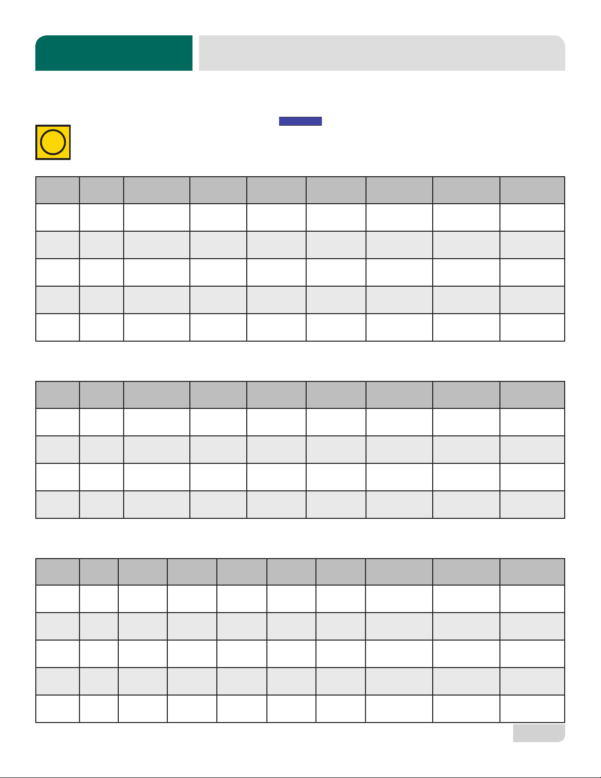
HT-180 HH 70° Rise (14 kW)
Volts Phase Freq Wash
Motor
Wash
Heater
Rinse
Heater Total Load MCA MOP
208 1 60 Hz 11.2 A 19.7 A 50.6 A 81.5 A 84.3 A 95.0 A
230 1 60 Hz 11.2 A 21.8 A 55.9 A 88.9 A 91.7 A 100.0 A
208 3 60 Hz 11.2 A 11.4 A 29.2 A 51.8 A 54.6 A 65.0 A
230 3 60 Hz 11.2 A 12.6 A 32.3 A 56.1 A 58.9 A 70.0 A
460 3 60 Hz 3.0 A 6.3 A 16.1 A 25.4 A 26.2 A 30.0 A
HT-180 HH 40° Rise (12 kW)
Volts Phase Freq Wash
Motor
Wash
Heater
Rinse
Heater Total Load MCA MOP
208 1 60 Hz 11.2 A 19.7 A 43.3 A 74.2 A 77.0 A 85.0 A
230 1 60 Hz 11.2 A 21.8 A 47.9 A 80.9 A 83.7 A 90.0 A
208 3 60 Hz 11.2 A 11.4 A 25.0 A 47.6 A 50.4 A 60.0 A
230 3 60 Hz 11.2 A 12.6 A 27.7 A 51.5 A 54.3 A 65.0 A
460 3 60 Hz 3.0 A 6.3 A 13.8 A 23.1 A 23.9 A 25.0 A
ELECTRICAL REQUIREMENTS
SPECIFICATIONS
On three-phase machines, imbalanced wild leg goes to L3.
Also see the Motor Rotation section.
NOTICE
Local codes may require more stringent protection than what is displayed here. Always verify with your electrical service
contractor that your circuit protection is adequate and meets all applicable national and local codes. Numbers in this manual
are for reference and may change without notice.
i
7
07610-004-26-29-H
ELECTRICAL REQUIREMENTS
SPECIFICATIONS
On three-phase machines, imbalanced wild leg goes to L3.
Also see the Motor Rotation section.
NOTICE
Local codes may require more stringent protection than what is displayed here. Always verify with your electrical service
contractor that your circuit protection is adequate and meets all applicable national and local codes. Numbers in this manual
are for reference and may change without notice.
HT-180 HH NB
Volts Phase Freq Wash
Motor
Wash
Heater
Rinse
Heater Total Load MCA MOP
208 1 60 Hz 11.2 A 19.7 A N/A 30.9 A 33.7 A 40.0 A
230 1 60 Hz 11.2 A 21.8 A N/A 33.0 A 35.8 A 45.0 A
208 3 60 Hz 11.2 A 11.4 A N/A 22.6 A 25.4 A 35.0 A
230 3 60 Hz 11.2 A 12.6 A N/A 23.8 A 26.6 A 35.0 A
460 3 60 Hz 3.0 A 6.3 A N/A 9.3 A 10.1 A 15.0 A
HT-180 HH S
Volts Phase Freq Wash
Motor
Wash
Heater
Rinse
Heater Total Load MCA MOP
208 1 60 Hz 11.2 A N/A N/A 11.2 A 14.0 A 25.0 A
230 1 60 Hz 11.2 A N/A N/A 11.2 A 14.0 A 25.0 A
208 3 60 Hz 11.2 A N/A N/A 11.2 A 14.0 A 25.0 A
230 3 60 Hz 11.2 A N/A N/A 11.2 A 14.0 A 25.0 A
i
Volts Phase Freq Wash
Motor
Wash
Heater
Rinse
Heater 1
Rinse
Heater 2 Total Load MCA MOP
208 1 60 Hz 11.2 A 19.7 A 19.7 A 36.1 A 86.7 A 89.5 A 100.0 A
230 1 60 Hz 11.2 A 21.8 A 21.8 A 39.9 A 94.7 A 97.5 A 105.0 A
208 3 60 Hz 11.2 A 11.4 A 11.4 A 20.9 A 54.9 A 57.7 A 65.0 A
230 3 60 Hz 11.2 A 12.6 A 12.6 A 23.1 A 59.5 A 62.3 A 70.0 A
460 3 60 Hz 3.0 A 6.3 A 6.3 A 11.5 A 27.1 A 27.9 A 30.0 A
HT-180 HH VER

07610-004-26-29-H
8
INSTRUCTIONS
INSTALLATION
Before installing the unit, check the packaging and machine for damage. If the packaging
is damaged, the machine might also be damaged. If there is damage to both packaging
and machine, do not throw away the packaging. The machine has been inspected and
packed at the factory and is expected to arrive to you in new, undamaged condition.
However, rough handling by carriers or others might result in damage to the unit while
in transit. If so, do not return the unit to the manufacturer. Instead, contact the carrier
and ask them to send a representative to the site to inspect the damage and complete
an inspection report. You must contact the carrier and the dealer that sold you the unit
within 48 hours of receiving the machine.
While unpacking the machine, ensure that there are no missing parts. If an item is
missing, contact the manufacturer immediately.
While unpacking an HH VER unit, note that the VER system is packaged separately.
Click here or on the instructions icon for a guide on mounting the VER system to the
machine.
The machine must be level in its operating location to prevent damage to the machine
during operation and to ensure the best results. The unit comes with four adjustable
bullet feet, which can be turned using a pair of channel locks (or by hand if the unit can
be raised safely). Ensure that the unit is level from side-to-side and front-to-back before
making any connections.
Plumbing connections must comply with all applicable local, state, and national
plumbing codes. The plumber is responsible for ensuring that the incoming water line
is thoroughly ushed before connecting it to any component of the machine. It is very
important to remove all foreign debris from the water line that might potentially get
trapped in the valves or cause an obstruction. Any valves that are fouled as a result of
foreign matter left in the water line—and any expenses resulting from this fouling—are
not the responsibility of the manufacturer.
A water hardness test must be performed to determine if a water treatment system
needs to be installed.
If water hardness tests at greater than 3 GPG, install the Scaltrol Water Treatment
system (see the Plumbing Options page) into the water line before the machine’s
incoming water connection point. A water shut-o valve should be installed to allow
access for service.
INSPECTION
LEVELING
UNPACKING
PLUMBING
A water hardness test
MUST be performed.
Do not throw away
packaging if damage is
evident!
WATER SUPPLY
CONNECTION:
WATER HARDNESS
GREATER THAN
3 GPG
The plumber MUST ush
the incoming water line!
HH VER
ASSEMBLY

9
07610-004-26-29-H
WATER SUPPLY
CONNECTION:
WATER HARDNESS
OF 3 GPG OR LESS
PRESSURE
REGULATOR
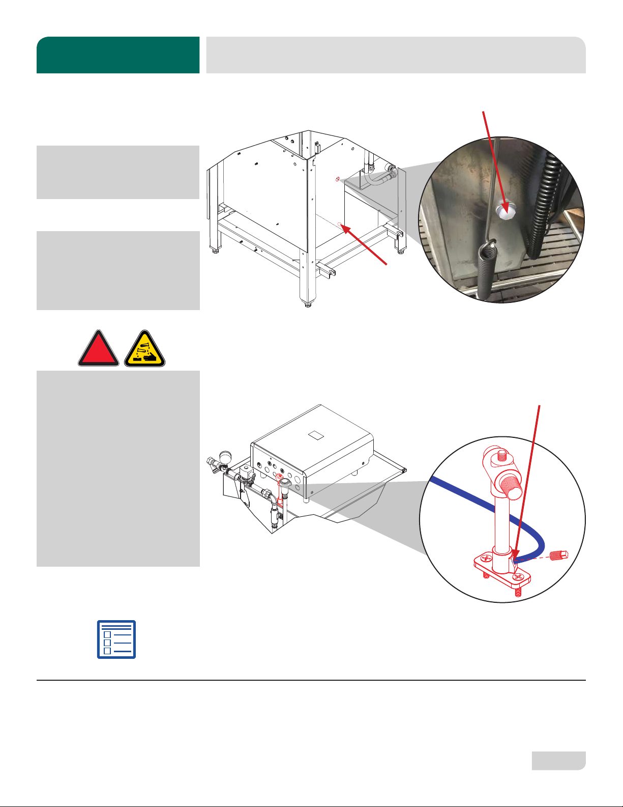
SHOCK ABSORBER
CONNECTING THE
DRAIN LINE
If water hardness tests at less than 3 GPG, install the water supply line directly to
the machine’s incoming water connection point. A water shut-o valve should be
installed to allow access for service.
The steam machines come with lines to connect the source steam. Connect all steam
lines to the machine as all applicable codes provide. See machine data plate for
information concerning steam ow pressure. Click here or on the instructions icon for
the Steam Booster manual.
The manufacturer recommends the installation of a water pressure regulator in the
incoming water line to ensure proper owrate at all times and oers these devices as
options (see the Plumbing Options page). The PRV comes standard on the HH VER.
Do not confuse static pressure with ow pressure. Static pressure is the line pressure
in a “no ow” condition (all valves and services are closed). Flow pressure is the
pressure in the ll line when the ll valve is opened during the cycle.
The manufacturer also recommends the installation of a shock absorber in the
incoming water line and oers these devices as options. This prevents line hammer/
hydraulic shock—induced by the solenoid valve as it operates—from causing damage
to the equipment (see the Plumbing Options page).
The machine's drain is a gravity-discharge drain. All piping from the 1 1/2” NPT
connection on the wash tank must be pitched (1/4” per foot) to the oor or sink drain.
All piping from the machine to the drain must be a minimum 1 1/2” NPT and must not
be reduced. There must also be an air-gap between the machine drain line and the
oor sink or drain. If a grease trap is required by code, it should have a ow capacity
of 5 GPM.
Determine which exhaust fan timer is on the machine (located in the control box)
and click the instructions icon beside that timer to access programming instructions.
STEAM LINE
CONNECTION
INSTRUCTIONS
INSTALLATION
EXHAUST FAN
TIMER
07610-004-26-29-H
10
INSTRUCTIONS
INSTALLATION
CHEMICAL
CONNECTIONS
PLUMBING CHECK Slowly turn on the water supply to the machine after the incoming ll line and drain
line have been installed. Check for any leaks and repair as required. All leaks must be
repaired before operating the machine.
Detergent
Connect detergent by removing the bulkhead tting on the back of the machine and
replacing it with the appropriate dispensing equipment.
Chemical connections
should be made by the
chemical supplier.
Rinse-aid
Connect rinse-aid by removing one of the brass plugs at the base of the rinse injector
and replacing it with the appropriate dispensing equipment. See the "Plumbing - HH
VER" page for a depiction of the VER rinse injector.
Rinse-aid
Using deionized water or
other aggressive uids
will result in corrosion and
failure of components and
will void the warranty.
WARNING! Some of the
chemicals used in
dishwashing may cause
chemical burns if they
come in contact with skin.
Wear protective gear when
handling these chemicals.
If any skin comes in
contact with these
chemicals, immediately
follow the instructions
provided with the
chemicals for treatment.
!
WARNING
Dispenser Electrical Connections
The electrical connections for chemical dispensers are made on a fuse block inside
the control box. Click here for a depiction of the fuse block and connection locations.
Detergent Probe
Installs Here
11
07610-004-26-29-H
Electrical and grounding conductors must comply with the applicable portions of the
National Electric Code ANSI/NFPA 70 (latest edition) and/or other electrical codes.
The data plate is located on the right side of the machine. Refer to the data plate for
machine operating requirements, machine voltage, total amperage, and serial number.
1. Open the control box by using a phillips screwdriver to remove the four screws on
the front cover of the control box.
2. Install 3/4” conduit into the pre-punched holes in the back of the control box.
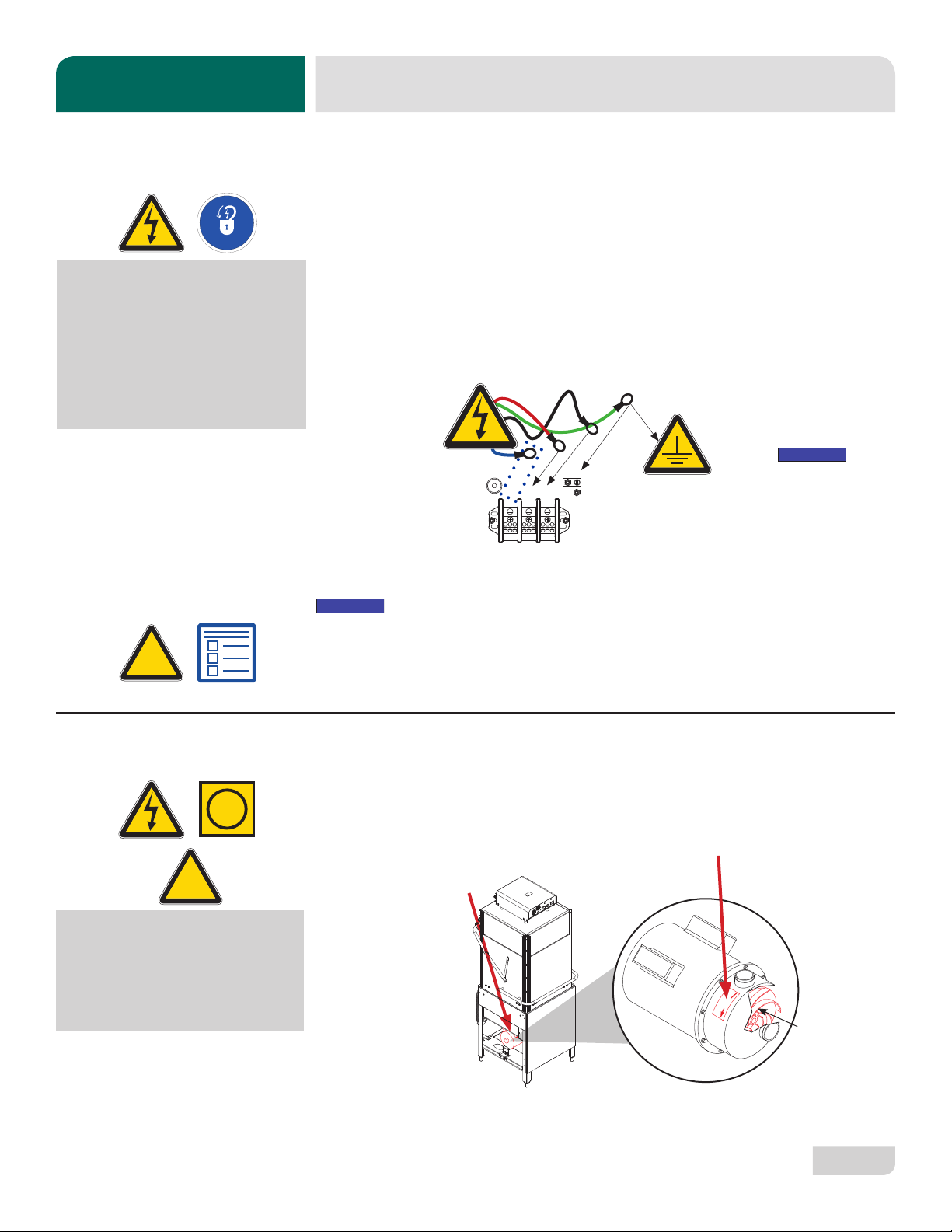
3. Route power wires and connect to power block and grounding lug.
4. Install the service wires (L3 for 3-Phase only) to the appropriate terminals as they
are marked on the terminal block.
5. Install the grounding wire into the lug provided.
6. Tighten the connections.
“DE-OX” or similar anti-oxidation agent should be used on all power
connections.
CAUTION! Improperly connecting external devices can cause damage to the
machine and/or electrical infrastructure! Click here for a wiring guide.
On 3-Phase machines only, correct pump motor rotation must be veried before
the machine is operated. Failure to do so can result in damage to the machine and
components.
1. Follow the "Filling the Wash Tub" section.
2. Locate the wash pump motor and identify the arrow decal which shows the
correct motor rotation.
3. Flip the mode switch to "MANUAL" and start the machine.
4. Observe the rotation of impeller and quickly stop the machine.
5. If rotation is incorrect, disconnect electrical power and reverse the
L1 and L2 connections at terminal block shown in the section above.
ELECTRICAL POWER
CONNECTIONS
Disconnect electrical
power supplies and
lockout/tagout in
accordance with
appropriate procedures
and codes at the
disconnect switch.
!
CAUTION
INSTRUCTIONS
INSTALLATION
Imbalanced
wild leg goes
to L3.
NOTICE
L1
L2
L3
Ground
3Φ
NOTICE
MOTOR ROTATION
i
CAUTION! On 3-Phase
machines only, correct
pump motor rotation
must be veried
before operation!
!
CAUTION
Rotation
Impeller

07610-004-26-29-H
12
Ensure that the power switch is in the "OFF" position and apply power to machine.
Check the incoming power at the terminal block and ensure it corresponds with the
voltage listed on the data plate. If not, contact a qualied service agency to examine
the problem. Do not run machine if voltage is too high or too low. Shut o the service
breaker and advise all proper personnel of the location of the breaker and any prob-
lems. Replace the control box cover and tighten-down the screws.
This is a commercial machine and reaches temperatures that can exceed those
generated by a residential machine. Surrounding countertops, cabinets, ooring ma-
terial, and subooring material must be designed and/or selected with these higher
temperatures in mind.
Any damage to surrounding area caused by heat/moisture to materials that
are not recommended for higher temperatures will not be covered under
warranty or by the manufacturer.
The temperature setpoints on this unit have been set at the factory. They should
only be adjusted by an authorized service agent.
The manufacturer oers an optional False Panel Kit for corner installations. See the
Kits page for kit part number. Click here for false panel/corner install instructions.
The manufacturer does NOT endorse "Tankless On-demand" water heaters
for use with their dishmachines. The manufacturer DOES endorse, and highly
recommends, the standard "Tank" style water heaters, sized to properly handle the
water heating requirements of the facility.
TEMPERATURE
SETPOINTS
SURROUNDING
AREA
VOLTAGE CHECK
i
NOTICE
INSTRUCTIONS
INSTALLATION
FALSE PANEL/
CORNER INSTALL
FACILITY HOT
WATER HEATER

13
07610-004-26-29-H
OPERATING INSTRUCTIONS
OPERATION
Before operating the unit, verify the following:
1. The tank is clean and free of debris.
2. The wash arms, rinse arms, sump strainer, and scrap screen are all installed
correctly.
3. The standpipe is installed.
To energize the unit, turn on the power at the service breaker. The voltage should
have been previously veried as being correct. If not, the voltage will have to be
veried.
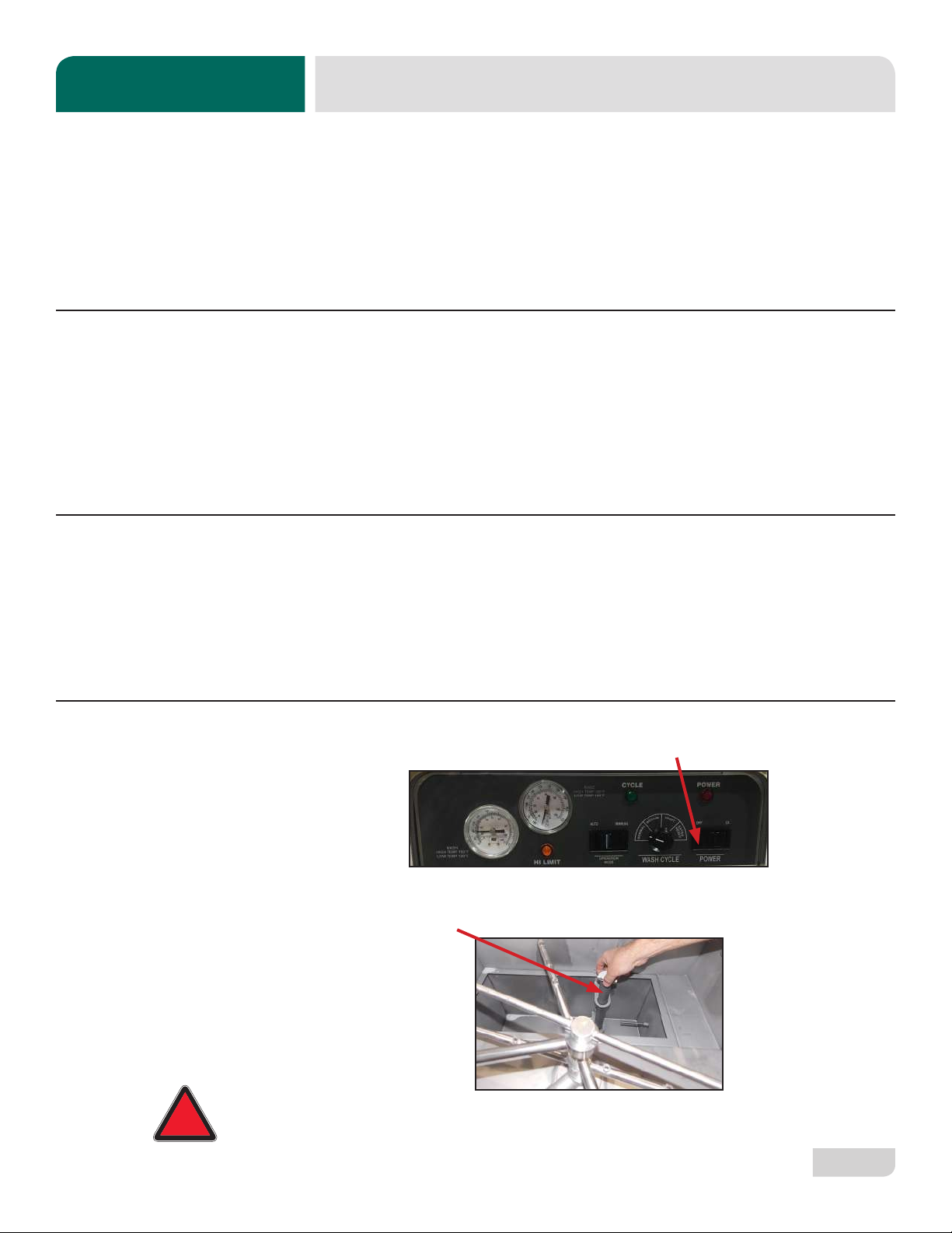
Ensure that the mode switch is in the "AUTO" position, and place the power switch
into the "ON" position. The machine will ll automatically and shut-o when the
appropriate level is reached (just below the scrap screen). The wash tub must be
completely lled before operating the wash pump to prevent damage to components.
Once the wash tub is lled, the unit is ready for operation.
Proper ware preparation will help ensure good results and fewer re-washes. If not
prepared properly, ware might not come out clean and the eciency of the machine
will be reduced. Putting unscraped dishes into the machine aects its performance,
so scraps should always be removed from ware before being loaded into a rack.
Pre-rinsing and pre-soaking are good ideas, especially for silverware and casserole
dishes.
Place cups and glasses upside-down in racks so they don't hold water during the
cycle. The machine sanitizes as well as cleans. To do this, ware must be properly
prepared before being placed in the machine.
Refer to the “Preparation” section and follow the instructions there. Afterward, ensure
that chemicals are supplied to the machine. If not, contact your chemical supplier.
PREPARATION
POWER UP
WARE
PREPARATION
FILLING THE
WASH TUB
DAILY MACHINE
PREPARATION
Standpipe
Wash & Rinse Arms, Scrap Screen Sump Strainer
07610-004-26-29-H
14
For the rst operation of each day, it might be necessary to run the machine through
three cycles to ensure that all of the cold water is out of the system and to verify that
the unit is operating correctly. To cycle the machine, ensure that the power is on and
that the tub has lled to the correct level. Lift and close the door and the cycle light will
illuminate. The unit will start, run through the cycle, and shut-o automatically. Repeat
this two more times. The unit should now be ready to wash a rack of ware.
To wash a rack, open the door completely (avoiding hot water that might drip from
the door) and slide the rack into the unit.
Close the door and the unit will start automatically. Once the cycle is complete, open
the door (again watching for the dripping hot water) and remove the rack of clean
ware. Replace with a rack of soiled ware and close the door. Repeat this process.
Based on use, the scrap screen might become clogged with soil and debris as the
workday progresses. Operators should regularly inspect the scrap screen to ensure
it has not become clogged. If clogged, it will reduce the washing capability of the
machine. Instruct operators to clean-out the scrap screen at regular intervals or as
required by workload. Do NOT beat strainers to remove debris.
1. Turn machine off by flipping the power switch to “OFF.”
2. Open the door and allow steam/heat to escape.
3. Remove the standpipe and allow the tub to drain.
WARNING! Wash tank water will be hot!
WARM-UP CYCLES
WASHING A RACK
OF WARE
OPERATIONAL
INSPECTION
SHUTDOWN &
CLEANING
!
WARNING
OPERATING INSTRUCTIONS
OPERATION
Other manuals for HT-180 HH
1
This manual suits for next models
4
Table of contents
Other Noble Dishwasher manuals


