Noble CG-1200 Setup guide

INSTALLATION, OPERATION,
AND SERVICE MANUAL
NOBLE CG-1200
NOBLE CG-115
CG-1200/CG-115 Manual • 07610-004-26-27-F
NOBLE GLASSWASHER DISHMACHINES

i
REVISION HISTORY
Revision
Letter Revision
Date Made by Applicable ECNs Details
A 7-23-15 KAP QOF-386 Initial release of manual.
B 1-19-16 JH QOF-386 Added CG-115 and associated views, parts lists, and schematics to the
manual.
C 4-26-16 JH 8379 Updated schematic on pg. 48.
D 9-21-16 JH N/A Updated manual to new format.
Removed “iodine” and "type of sanitizer used" from pg. 8.
Replaced exploded views throughout with more legible views.
Updated P/N of Power Disconnect Decal on pgs. 35 and 36.
Updated P/N of item #8 on pg. 37.
Updated P/N of item #1 on pg. 40.
Updated P/N and description of item #13 on pg. 43.
Updated P/N and description of item #15 on pg. 43.
E 7-12-17 JH 8453 Corrected pg. 2, switched "Hot" and "Cold."
Corrected ow pressure on pg. 3.
Added Iodiphor as a sanitizer on pg. 3 and updated the reference to
sanitizers on pg. 8.
Corrected P/N of item #4 on pg. 35 and item #6 on pg. 36.
Changed P/N of item #7 and added P/N for entire bottom inlet manifold
assembly on pg. 39.
Added view and image of drain o-ring installation to pg. 41.
Added rinse strainer, wash tank, and o-ring to pgs. 41 and 42.
Changed P/N of item #10b on pg. 42.
F 6-18-18 JH 8593
8633 Updated instructions on pgs. 11-14 to show stop caps.
Added deliming instructions to pg. 15.
Added bottom stop cap and top stop cap with hardware to pgs. 39-40.
Changed P/N of item #7 on pg. 40.
Added optional accumulator tray kit to pg. 42.
Added deector strainer to pgs. 43-44.

The manufacturer provides
technical support for all of
the dishmachines detailed
in this manual. We strongly
recommend that you refer to
this manual before making a
call to our technical support
sta. Please have this manual
open when you call so that our
sta can refer you, if necessary,
to the proper page. Technical
support is not available on
holidays. Contact technical
support toll free at
1-888-800-5672.
Technical support is available
for service personnel only.
ii
NOMENCLATURE
CG-1200
208 V glasswasher dishmachine; chemical-sanitizing,
carousel-type, electric tank heat, with detergent, rinse-aid,
and sanitizer chemical feeder pumps.
CG-115
115 V glasswasher dishmachine; chemical-sanitizing,
carousel-type, electric tank heat, with detergent, rinse-aid,
and sanitizer chemical feeder pumps.

iii
GUIDES
Symbols............................................................................................................................................1
Abbreviations & Acronyms ...............................................................................................................1
SPECIFICATIONS
Machine Dimensions........................................................................................................................2
Operating Parameters......................................................................................................................3
Electrical Requirements ...................................................................................................................4
INSTALLATION
Installation Instructions.....................................................................................................................5
Inspection......................................................................................................................... 5
Unpacking........................................................................................................................ 5
Leveling............................................................................................................................ 5
Plumbing.......................................................................................................................... 5
Pressure Regulator.......................................................................................................... 6
Shock Absorber ............................................................................................................... 6
Connecting the Drain Line ............................................................................................... 6
Plumbing Check............................................................................................................... 6
Electrical Power Connections.......................................................................................... 7
Voltage Check.................................................................................................................. 7
Surrounding Area............................................................................................................. 7
Thermostats..................................................................................................................... 8
Chemical Feeder Equipment ........................................................................................... 8
Preparing Chemical Feeder Pumps................................................................................. 8
Priming Chemical Feeder Pumps.................................................................................... 8
OPERATION
Operating Instructions......................................................................................................................9
Preparation ...................................................................................................................... 9
Filling the Wash Tub ........................................................................................................ 9
Ware Preparation........................................................................................................... 10
Washing a Rack of Ware ............................................................................................... 10
Operational Inspection................................................................................................... 10
Shutdown & Cleaning .....................................................................................................11
After Cleaning................................................................................................................ 13
Detergent Control........................................................................................................... 15
Deliming......................................................................................................................... 15
TABLE OF CONTENTS

MAINTENANCE
Preventative Maintenance..............................................................................................................16
TROUBLESHOOTING
Common Problems.........................................................................................................................17
SERVICE PROCEDURES
Chemical Feeder Pump Motor Replacement.................................................................................21
Wash Tank Heater Replacement....................................................................................................24
Thermostat Replacement...............................................................................................................29
Wash Motor Replacement..............................................................................................................32
PARTS
Control Box Assembly - CG-1200 ..................................................................................................35
Control Box Assembly - CG-115.....................................................................................................36
Outer Shell Assembly.....................................................................................................................37
Chemical Feeder Pump Assembly.................................................................................................38
Rinse Assembly..............................................................................................................................39
Wash System .................................................................................................................................41
Conveyor & Drive System..............................................................................................................43
Door Assembly...............................................................................................................................45
SCHEMATICS
CG-1200.........................................................................................................................................46
CG-115...........................................................................................................................................47
iv
TABLE OF CONTENTS

07610-004-26-27-F 1
SYMBOLS
!
CAUTION
!
WARNING
NOTICE
- risk of injury to personnel.
- risk of damage to equipment.
- risk of electrical shock.
- lockout electrical power.
- reference data plate.
- important note.
i
- caustic chemicals.
ABBREVIATIONS & ACRONYMS
ANSI - American National Standards Institute
GHT - Garden Hose Thread
GPH - Gallons per Hour
GPM - Gallons per Minute
GPG - Grains per Gallon
HP - Horse Power
Hz - Hertz
ID - Inside Diameter
kW - Kilowatts
NFPA - National Fire Protection Association
NPT - National Pipe Thread
PPM - Parts per Million
PSI -Pounds per Square Inch
V- Volts
- ground wire.
GUIDES

2
07610-004-26-27-F
All dimensions are for reference only and are subject to change without notice.
*Cut view showing machine base from top.
MACHINE DIMENSIONS
SPECIFICATIONS
NOTICE
LEGEND
A - Electrical Connection
B - Water Inlet, Hot, 1/2”
C - Water Inlet, Cold, 1/2”
D - Drain Connection, 1 1/2”
All dimensions from the floor can be
increased 1 1/4" using the machine's
adjustable feet.
B
C
D
B
C
A
D
25 1/4”
[641 mm]
9 1/2”
[241 mm]
5”
[127 mm]
25”
[635 mm]
14 5/8”
[372 mm] 8 5/8”
[220 mm]
12 7/8”
[327 mm]
A
2 1/2”
[64 mm]
12”
[305 mm]
Dish Clearance
6”
[152 mm] 6”
[152 mm]
9”
[229 mm]
29 1/4”
[743 mm]
19 1/2”
[495 mm]
2” MIN
[51 mm]
25 5/8”
[652 mm]
27 5/8”
[703 mm]
TOP
FRONT SIDE
*

07610-004-26-27-F 3
Operating Capacity: CG-1200 CG-115
Glasses per Hour 1200 1200
Operating Cycle (Seconds):
Total Cycle Time 120 120
Tank Capacity (Gallons): 3.0 3.0
Wash Pump Capacity (GPM): 55 55
Water Temperatures (°F):
Minimum Wash Temperature 130 130
Minimum Rinse Temperature 75 75
Other Water Requirements:
Cold Water Flow Pressure (PSI) 20 ± 5 20 ± 5
Hot Water Flow Pressure (PSI) 20 ± 5 20 ± 5
Gallons per Hour 10.0 10.0
Water Line Size (NPT) 1/2" 1/2"
Drain Line Size (NPT) 1 1/2" 1 1/2"
Minimum Chlorine Required (PPM) 50 50
Minimum Iodiphor Required (PPM) 12.5 12.5
Electrical Loads (as applicable):
Wash Motor (HP) 0.1 0.1
Wash Heater (kW) 2.7 (208 V)/3.3 (230 V) 1.3
Always refer to the machine data plate for specic electrical and water require-
ments. The material provided on this page is for reference only and is subject
to change without notice.
NOTICE
i
OPERATING PARAMETERS
SPECIFICATIONS

4
07610-004-26-27-F
All electrical ratings provided in this manual are for reference
only.Always refer to the machine data plate to get exact electrical
information for this machine. All electrical work performed on
machines should be done in accordance with applicable
local, state, territorial, and national codes. Work should only
be performed by qualied electricians and authorized service
agents.
Note that all electrical wiring used in the CG- series of machines
must be rated, at a minimum, for 212 °F (100 °C), and that only
copper conductors must be used.
Where applicable, heating element amperage draws have been
adjusted for the assumed input voltage. The manufacturer
assumes incoming voltages will be either 208 or 230 Volts. Some
heating elements used in the machines could be rated for other
voltages, so always verify the amperage draw of the machine in
operation when sizing circuit protection.
If the dishmachine is equipped with an optional rinse heater, note
the rinse heater might have its own electrical connection and
require a separate service.Amperage loads for motors and heaters
are indicated on the machine data plate.
CG-1200
Electrical Characteristics
VOLTS 208 230
PHASE 1 1
FREQ 60 60
WASH
MOTOR
AMPS 0.5 A 0.4 A
WASH
HEATER
AMPS 13.0 A 14.4 A
TOTAL
LOAD 13.5 A 14.8 A
NOTICE
i
CG-115
Electrical Characteristics
VOLTS 115
PHASE 1
FREQ 60
WASH
MOTOR
AMPS 3.1 A
WASH
HEATER
AMPS 11.3 A
TOTAL
LOAD 14.4 A
ELECTRICAL REQUIREMENTS
SPECIFICATIONS

07610-004-26-27-F 5
Before installing the unit, check packaging and machine for damage. Damaged
packaging might be an indication of damage to the machine. If there is any type
of damage to both packaging and unit, do not throw away the packaging. The
dishmachine has been inspected at the factory before shipping and is expected to
arrive in new, undamaged condition. However, rough handling by carriers or others
might result in damage to the unit while in transit. If this occurs, do not return the unit to
the manufacturer. Instead, contact the carrier and ask them to send a representative
to the site to inspect the damage and request that an inspection report be completed.
Contact the carrier within 48 hours of receiving the machine as well as the dealer that
sold you the unit.
The machine should be unpacked and removed from the pallet before installing.
Remove all of the materials from inside. Once unpacked, verify there are no missing
parts. If a part is missing, contact the manufacturer immediately.
The dishmachine is designed to operate while level. This is important to prevent any
damage to the machine during operation and to ensure the best possible results. The
unit comes equipped with adjustable bullet feet which can be turned using a pair of
pliers. Verify the unit is level from front-to-back and side-to-side before making any
electrical or plumbing connections.
All plumbing connections must be made to adhere to local, state, territorial, and
national codes. The installing plumber is responsible for ensuring the incoming
water lines are ushed of debris before connecting to the machine. Note that chips
and materials from cutting processes can become lodged in the solenoid valves
and prevent them from opening or closing. Any valves that are found to be fouled
or defective because of foreign matter left in the water line, and any subsequent
damage, are not the responsibility of the manufacturer.
Cold water supply must be a minimum of 75 °F with a capacity of 180 GPH at 8-12
PSI. Hot water supply must be a minimum of 120 °F (CG-1200)/130 °F (CG-115) with
a capacity of 10 GPH at 20 ± 5 PSI. Incoming hot and cold water service connections
(supplied by customer) must be a 1/2” NPT pipe size minimum. Install the water
supply line to the dishmachine using copper pipe. It is recommended that a water
shut-o valve be installed in the water line between the main supply and the machine
to allow access for service.
INSPECTION
Do not throw away
container if damage is
evident!
UNPACKING
PLUMBING
The plumber must ush
the incoming water line!
LEVELING
INSTRUCTIONS
INSTALLATION

6
07610-004-26-27-F
PRESSURE
REGULATOR
SHOCK ABSORBER
CONNECTING THE
DRAIN LINE
The manufacturer has an optional water pressure regulator to accommodate areas
where water pressure uctuates or is higher than the recommended pressure. Take
care not to confuse static pressure with ow pressure: static pressure is line pressure in
a “no ow” condition (all valves and services are closed); ow pressure is the pressure
in the ll line when the valve is opened during the cycle.
It is suggested that a shock absorber (not supplied) be installed on the incoming water
line. This prevents water hammer (hydraulic shock)—induced by the solenoid valve
as it operates—from causing damage to the equipment.
The CG- glasswashers have a gravity drain (2” NPT connection). All piping from the
machine to the drain must be a minimum 2” NPT and must not be reduced. There
must also be an air-gap between the machine drain line and the oor sink or drain. If
a grease trap is required by code, it should have a ow capacity of 5 GPM.
After installing the incoming ll line and the drain line, slowly turn on the water supply
to the machine. Check for any leaks and repair as required. All leaks must be
repaired before operating the machine.
Take care not to confuse
static pressure with
ow pressure!
PLUMBING CHECK
INSTRUCTIONS
INSTALLATION

07610-004-26-27-F 7
Electrical and grounding conductors must comply with the applicable portions of the
National Electric Code ANSI/NFPA 70 (latest edition) and/or other electrical codes.
The data plate is on the ride side of the door. Refer to the data plate for machine operating
requirements, machine voltage, total amperage, and serial number.
Remove the electrical box cover. This will require removing the screws at the bottom
with a phillips screwdriver and lifting it up and o. Install 3/4” conduit from the underside
of the machine to the hole in the rear of the electrical box. Route power wires and
connect to power block and grounding lug. Install the service wires (L1 and L2) to the
appropriate terminals as they are marked on the terminal block. Install the grounding
wire into the lug provided. It is recommended that “DE-OX” or another similar anti-
oxidation agent be used on all power connections.
Ensurethatthe"Power"switchisinthe"OFF"positionandapplypowertodishmachine.
Check the incoming power at the terminal block and ensure it corresponds with the
voltage listed on the data plate. If not, contact a qualied service agency to examine
the problem. Do not run dishmachine if voltage is too high or too low. Shut-o the
service breaker and advise all proper personnel of the location of the breaker and any
problems. Replace the electrical box cover and tighten-down the screws.
This is a commercial dishmachine and reaches temperatures that can exceed
those generated by a residential machine. Surrounding countertops, cabinets, ooring
material, and suboor material must be designed and/or selected with these higher
temperatures in mind.
CAUTION! Any damage to surrounding area that is caused byheatand/or moisture to
materials that are not recommended for higher temperatures will not be covered under
warranty or by the manufacturer.
ELECTRICAL POWER
CONNECTIONS
Disconnect electrical
power at the breaker or
disconnect switch and
tag-out in accordance with
procedures and codes.
SURROUNDING
AREA
VOLTAGE CHECK
i
L1 L2 GRND
INSTRUCTIONS
INSTALLATION
!
CAUTION

8
07610-004-26-27-F
CHEMICAL FEEDER
EQUIPMENT
PRIMING CHEMICAL
FEEDER PUMPS
WARNING! Some of the
chemicals used in
dishwashing might cause
chemical burns if they
come in contact with skin.
Wear protective gear when
handling these chemicals.
If any contact with skin
occurs, immediately
follow the treatment
instructions provided
with the chemicals.
PREPARING
CHEMICAL FEEDER
PUMPS
The thermostats on this dishmachine have been set at the factory. They should only
be adjusted by an authorized service agent.
CAUTION! Chlorine-based sanitizers can be detrimental to this machine
if the chemical solution is too strong. See a chemical professional to
ensure the dispenser is set-up correctly.
It is important to remember that if you decide to operate the unit in chemical-sanitizing
mode, you must ensure an appropriate sanitizer (chlorine or iodiphor, see Operating
Parameters page for concentrations) is used in the nal rinse line.
The CG- dishmachines are supplied with detergent, rinse-aid, and sanitizer chemical
feeder pumps.
Locate the open ends of the chemical tubes with the tube stieners and place each
one in the appropriate container.
A. Red Tubing = Detergent B. Blue Tubing = Rinse-aid
C. White Tubing = Sanitizer
Chemical feeder pumps need priming when the machine is rst installed or if the
chemical lines have been removed and air is allowed to enter.
CAUTION! Water must be in the sump and wash tank before chemicals
are dispensed. This equipment is not recommended for use with deionized
water or other aggressive uids.
1. Verify that the proper chemical tube stiener inlet is in the proper container.
2. Use the push buttons on the right side of control box to prime each pump.
3. To prime the pumps, hold down each prime switch until the chemical can be
seen owing through the chemical tubes.
4. Detergent is dispensed as required during the wash tank ll. The amount of
detergent might need to be increased or decreased depending on water quality
and type of detergent. It is adjusted by turning the potentiometer on the speed
control board clockwise to increase, counter-clockwise to decrease.
5. Rinse-aid is dispensed proportionally into the nal rinse water line. The amount
of rinse-aid might need to be adjusted depending on water quality and results. It
is adjusted by turning the potentiometer on the speed control board clockwise to
increase, counter-clockwise to decrease.
6. Sanitizer is dispensed proportionally into the nal rinse water line. The amount
of sanitizer might need to be adjusted depending on concentration. It is adjusted
by turning the potentiometer on the speed control board clockwise to increase,
counter-clockwise to decrease.
THERMOSTATS
!
CAUTION
!
WARNING !
CAUTION
INSTRUCTIONS
INSTALLATION
07610-004-26-27-F 9
Before operating the unit, verify the following:
1. Wash strainer is clean and in place.
2. Rinse strainer is clean and in place.
3. The drain stopper is installed.
4. Chemical levels in chemical containers are correct.
1. Place the “Power” switch in the “FILL” position.
2. The unit will automatically begin to fill.
3. Verify temperatures before operating the unit.
PREPARATION
FILLING THE
WASH TUB
OPERATING INSTRUCTIONS
OPERATION
10
07610-004-26-27-F
Proper preparation of ware will help ensure good results and fewer re-washes. If not
done properly, ware might not come out clean and the eciency of the dishmachine
will be reduced. Scraps should always be removed from ware before being loaded
onto the carousel. Pre-rinsing and pre-soaking are good ideas.
Place cups and glasses upside-down on the carousel so they don't hold water during
the cycle. The dishmachine sanitizes as well as cleans. To do this, ware must be
properly prepared before being placed in the machine.
1. Turn the power switch to the “ON” position; the carousel will begin to rotate.
2. Place glasses upside-down on the carousel.
3. When the glasses have completed the cycle, the paddle switch will activate,
turning o the water and carousel.
4. Remove clean glasses which are against the paddle switch.
5. The carousel will begin to rotate again.
Strainers can become clogged with soil and debris as the workday progresses.
Operators should regularly inspect strainers to ensure they have not become
clogged. Clogged strainers reduce the washing capability of the machine and should
be cleaned at regular intervals or as required by workload. See the next section.
WASHING A RACK
OF WARE
WARE
PREPARATION
OPERATIONAL
INSPECTION
OPERATING INSTRUCTIONS
OPERATION
Upper
Wash Strainer Rinse Strainer Separator Rinse Strainer

07610-004-26-27-F 11
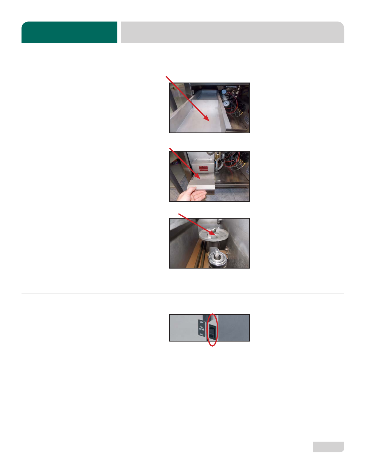
1. Turn power switch to the “OFF”
position.
2. Ensure glasses are removed from
carousel.
3. Remove and clean wash strainer.
4. Remove and clean drain stopper.
5. Remove curtain, clean with a mild
soap, and rinse.
SHUTDOWN &
CLEANING 6. Remove and clean drain boards.
7. Remove and clean rack cylinder.
8. Hold paddle switch against wall of
machine with one hand.
9. Remove carousel with other hand
and clean.
10. Rotate top stop cap counter-
clockwise until opening aligns with
top rinse arm.
OPERATING INSTRUCTIONS
OPERATION
CAUTION!
Do NOT beat strainers to
remove debris!
!
CAUTION
Disconnect electrical
power at the breaker or
disconnect switch and
tag-out in accordance with
procedures and codes.

12
07610-004-26-27-F
16. Remove wash arm from manifold.
17. On all arms: remove end-caps, clean
with a brush, and flush with fresh
water.
18. Remove and clean separator and
upper rinse strainer.
19. Remove and clean rinse strainer.
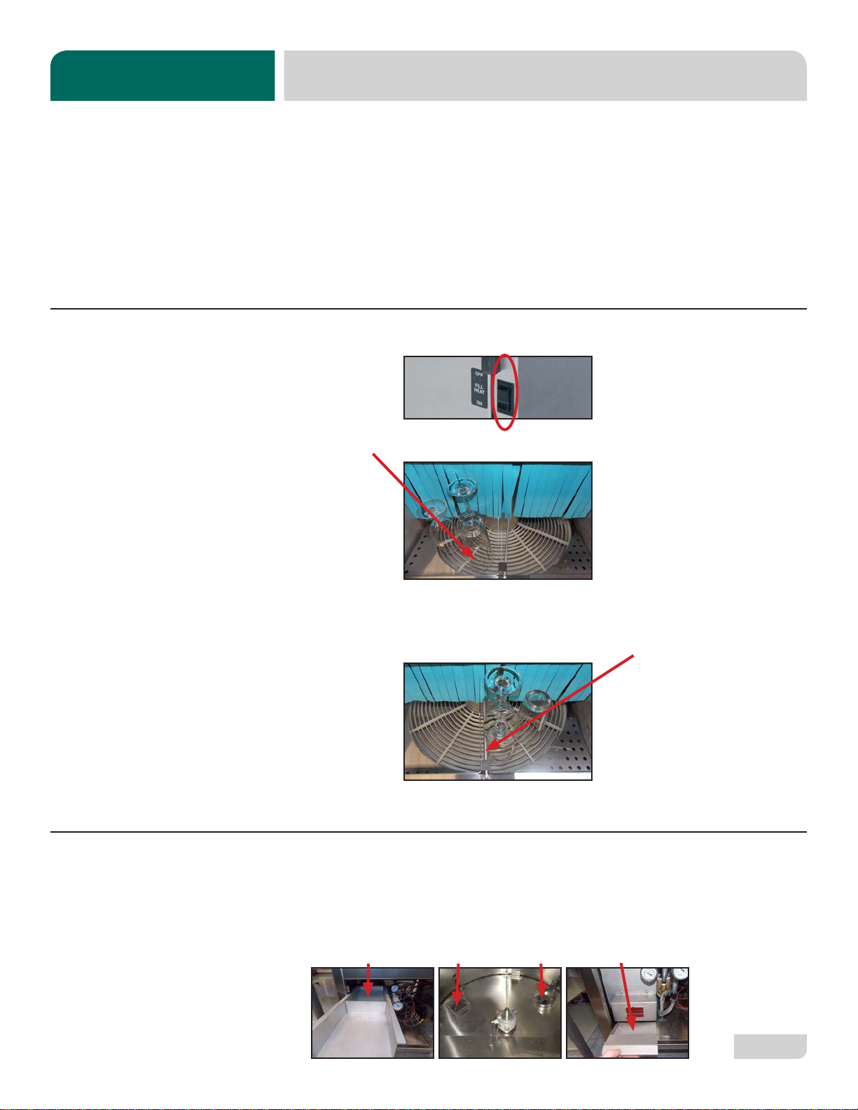
11. Remove rinse arm from manifold.
12. Rotate top stop cap counter-
clockwise until opening aligns with
top wash arm.
13. Remove wash arm from manifold.
14. Remove bottom stop cap.
15. Remove rinse arm from manifold.
SHUTDOWN &
CLEANING
OPERATING INSTRUCTIONS
OPERATION
CAUTION!
Do NOT beat strainers to
remove debris!
!
CAUTION
Bottom stop cap simply
lifts o the manifold.

07610-004-26-27-F 13
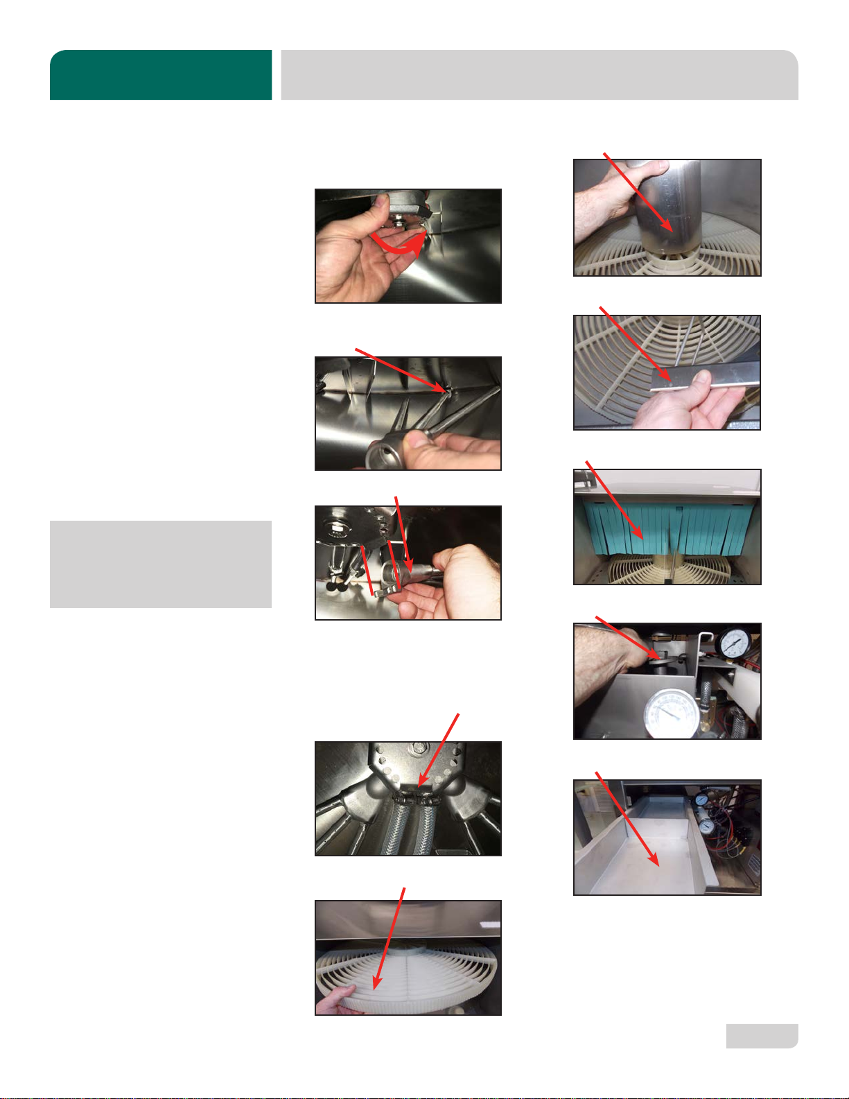
6. Insert middle of bottom rinse arm into
support bracket.
7. Push bottom rinse arm onto
manifold.
8. Replace bottom stop cap.
Stop cap must be oriented as shown!
9. Insert middle of top wash arm into
support bracket.
10. Push top wash arm onto manifold.
Align bottom of arm with guide tab on
stop cap for easy install.
1. Spray or wipe out interior of machine.
2. Replace rinse strainer.
3. Replace separator and upper rinse
strainer.
4. Insert middle of bottom wash arm
into support bracket.
5. Push bottom wash arm onto
manifold.
AFTER
CLEANING
OPERATING INSTRUCTIONS
OPERATION
NOTICE
CAUTION!
Ensure all components are
clean before replacing them
in the machine!
!
CAUTION
Top stop cap opening has a
guide tab which allows the
opening to easily be located
during arm install.
14
07610-004-26-27-F
16. Replace rack cylinder.
17. Replace drain boards.
18. Replace curtain.
19. Replace drain stopper.
20. Replace wash strainer.
21. Use stainless steel polish to clean
and protect outside of dishmachine.
11. Turn top stop cap counter-clockwise
until opening aligns with wash arm
location on manifold.
12. Insert middle of top rinse arm into
support bracket.
13. Push top rinse arm onto manifold.
Align bottom of arm with guide tab on
stop cap for easy install.
14. Turn top stop cap counter-clockwise
until the opening does NOT align
with either arm.
15. Replace carousel.
AFTER
CLEANING
OPERATING INSTRUCTIONS
OPERATION
Top stop cap opening has a
guide tab which allows the
opening to easily be located
during arm install.

07610-004-26-27-F 15
OPERATING INSTRUCTIONS
OPERATION
Detergent usage and water hardness are two factors that contribute greatly to how
eciently this dishmachine will operate. Using detergent in the proper amount can
become a source of substantial savings. A qualied water treatment specialist can
determine what is needed for maximum eciency from the detergent.
1. Hard water greatly aects the performance of the dishmachine, causing the
amount of detergent required for washing to increase. If the machine is installed
in an area with hard water, water treatment equipment should be installed.
2. Deposited solids from hard water can cause spotting that will not be removed
with a drying agent. Treated water will reduce this occurence.
3. Treated water might not be suitable for use in other areas of operation and it
might be necessary to install a water treatment unit for the water going to the
dishmachine only. Discuss this option with a qualied water treatment specialist.
4. Dishmachine operators should be properly trained on how much detergent is to
be used per cycle. Meet with a water treatment specialist and detergent vendor
to discuss a complete training program for operators.
5. This dishmachine requires that chemicals be provided for proper operation and
sanitization. Contact a chemical supplier with any questions.
6. Water temperature is an important factor in ensuring that the dishmachine
functions properly, and the machine's data plate details what the minimum
temperatures must be. If minimum requirements are not met, there is a possibility
that dishes will not be clean or sanitized.
7. Instruct dishmachine operators to observe the required temperatures and to
report when they fall below the minimum allowed. A loss of temperature can
indicate a larger problem.
In order to maintain the dishmachine at its optimum performance level, lime and
corrosion deposits must be removed. The frequency for deliming will be based on
water conditions. A deliming solution is available from your chemical supplier. Read
and follow all instructions on the label.
1. Disconnect the detergent pump.
2. Drain and refill the wash tank.
3. Add deliming solution per supplier's instructions.
4. Run machine the period of time recommended by chemical supplier.
5. Wait ve minutes, then inspect the inside of the machine. If the machine is not
delimed, run again.
6. Run two cycles to remove residual deliming solution.
DETERGENT
CONTROL
i
DELIMING
This manual suits for next models
1
Table of contents
Other Noble Dishwasher manuals


