Noble UH30-E Setup guide

INSTALLATION, OPERATION,
AND SERVICE MANUAL
NOBLE UH30-E
UH30-E Manual • 07610-004-45-09-D
NOBLE UNDERCOUNTER DISHMACHINES
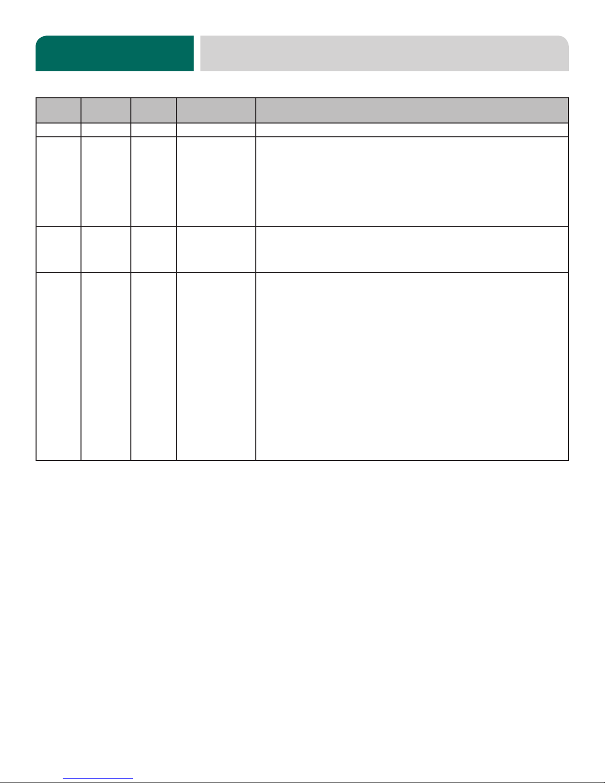
REVISION HISTORY
Revision
Letter
Revision
Date Made by Applicable ECNs Details
A 4-27-17 JH N/A Initial release of the manual.
B 9-6-17 JH 8532
Updated depiction of the air-gap on pg. 6.
Removed references to "screen" on pg. 20.
Added communication cable (05700-004-33-64) to pg. 23.
Corrected chemical tubes on pg. 25 and added tube length and color.
Removed ll line (05700-002-62-37) from wash hub on pg. 30.
Replaced 7/8" discharge hose with 5/8" discharge hose (05700-004-46-28) on pg. 31.
Updated view of inlet plumbing on pg. 34 to show angle of elbow and adapter.
Updated schematic to revision E.
C 1-19-18 JH 8537
8574
Added the UH30-E-SEER to the manual.
Updated the Door Assembly pages.
Added item #10 on pg. 48.
Corrected P/N for item #10 on pg. 52.
D 2-7-19 JH
8585
8599
8619
8648
Added PRV to view on pg. 3.
Added note about hot water heates to pg. 7.
Added motor rotation section to pg. 9.
Added programming instructions and fault codes to pgs. 22-26.
Updated P/N for item #2 on pg. 29.
Updated pg. 31 to show panel and membrane together.
Added item #14 on pg. 33.
Updated item #11 on pg. 40.
Added Door Interlock to pg. 41.
Changed rinse arm bearing assembly on pg. 44.
Changed rinse arm bearing kit P/N on pg. 44.
Updated SEER plumbing, pgs. 48-49.
Added note about water connection point to pg. 48.
Updated pgs. 54-55.
Added back panel and gaskets to pg. 56.
Added new drain water tempering kit and 460 V drain water tempering kit to pg. 57.
Updated schematics on pgs. 58-59.

i
UH30-E
Undercounter dishmachine; high-temperature, hot-water
sanitizing, with a booster tank and detergent
and rinse-aid chemical feeder pumps.
UH30-E-SEER
Undercounter dishmachine; high-temperature, hot-water
sanitizing, with a booster tank and detergent
and rinse-aid chemical feeder pumps. Equipped with Steam
Elimination and Energy Recovery System (SEER).
The manufacturer provides
technical support for all of
the dishmachines detailed
in this manual. We strongly
recommend that you refer to
this manual before making a
call to our technical support
sta. Please have this manual
open when you call so that our
sta can refer you, if necessary,
to the proper page. Technical
support is not available on
holidays.
Contact technical support toll
free at 1-888-800-5672.
Technical support is available
for service personnel only.
NOMENCLATURE

ii
TABLE OF CONTENTS
GUIDES
Symbols............................................................................................................................................ 1
Abbreviations & Acronyms ............................................................................................................... 1
SPECIFICATIONS
UH30-E Dimensions......................................................................................................................... 2
UH30-E-SEER Dimensions.............................................................................................................. 3
UH30-E Operating Parameters ........................................................................................................ 4
UH30-E-SEER Operating Parameters ............................................................................................. 5
Electrical Requirements ................................................................................................................... 6
INSTRUCTIONS
Installation Instructions..................................................................................................................... 7
Inspection......................................................................................................................... 7
Unpacking........................................................................................................................ 7
Plumbing.......................................................................................................................... 7
Water Supply Connections .............................................................................................. 7
Pressure Regulator.......................................................................................................... 8
Shock Absorber ............................................................................................................... 8
Connecting the Drain Line ............................................................................................... 8
Plumbing Check............................................................................................................... 8
Electrical Power Connections .......................................................................................... 9
Motor Rotation ................................................................................................................. 9
Voltage Check................................................................................................................ 10
Surrounding Area........................................................................................................... 10
Temperature Setpoints................................................................................................... 10
Leveling.......................................................................................................................... 10
Chemical Feeder Equipment ......................................................................................... 10
Preparing Chemical Feeder Pumps................................................................................11
Priming Chemical Feeder Pumps ...................................................................................11
Programming Chemical Feeder Pumps......................................................................... 12
Operating Instructions .................................................................................................................... 13
Preparation .................................................................................................................... 13
Power Up ....................................................................................................................... 13
Filling the Wash Tub ...................................................................................................... 13
Ware Preparation........................................................................................................... 14
Washing a Rack of Ware ............................................................................................... 14
Operational Inspection................................................................................................... 16
Shutdown & Cleaning .................................................................................................... 16
Deliming......................................................................................................................... 18
Detergent Control........................................................................................................... 19

iii
TABLE OF CONTENTS
MAINTENANCE
Preventative Maintenance.............................................................................................................. 20
TROUBLESHOOTING
Programming.................................................................................................................................. 22
Fault Codes .................................................................................................................................... 24
Troubleshooting.............................................................................................................................. 27
PARTS
Terminal Block Box, 208/230 V ...................................................................................................... 29
Terminal Block Box, 460 V ............................................................................................................. 30
Control Kick Panel.......................................................................................................................... 31
UH30-E Electrical Panel, 208/230 V .............................................................................................. 32
UH30-E Electrical Panel, 460 V ..................................................................................................... 33
UH30-E-SEER Electrical Panel, 208/230 V ................................................................................... 34
UH30-E-SEER Electrical Panel, 460 V .......................................................................................... 35
Chemical Feeder Pumps................................................................................................................ 36
Door................................................................................................................................................ 38
Miscellaneous Door Components .................................................................................................. 40
UH30-E-SEER Door Interlock ........................................................................................................ 41
Wash & Motor................................................................................................................................. 42
Rinse Manifold................................................................................................................................ 44
Plumbing Options ........................................................................................................................... 45
UH30-E Plumbing........................................................................................................................... 46
UH30-E-SEER Plumbing................................................................................................................ 48
Rinse Plumbing .............................................................................................................................. 50
Rinse Tank...................................................................................................................................... 52
SEER System................................................................................................................................. 54
Stands & Panels............................................................................................................................. 56
Miscellaneous Parts ....................................................................................................................... 57
SCHEMATICS
208/230 V, 50/60 Hz, 1 Phase ....................................................................................................... 58
460 V, 60 Hz, 3 Phase ................................................................................................................... 59

1
07610-004-45-09-D
GUIDES
SYMBOLS
ABBREVIATIONS & ACRONYMS
ANSI - American National Standards Institute
GHT - Garden Hose Thread
GPG - Grains per Gallon
GPM - Gallons per Minute
HP - Horse Power
Hz - Hertz
ID - Inside Diameter
kW - Kilowatts
NFPA - National Fire Protection Association
NPT - National Pipe Thread
OD - Outside Diameter
PRV - Pressure Regulating Valve
PSI -Pounds per Square Inch
V- Volts
!
CAUTION
!
WARNING
NOTICE
- Risk of Injury to Personnel
- Risk of Damage to Equipment
- Risk of Electrical Shock
- Lockout Electrical Power
- Reference Data Plate
- Important Note
i
- Caustic Chemicals
- Instructions Hyperlink

07610-004-45-09-D 2
SPECIFICATIONS UH30-E DIMENSIONS
1/4
[7 mm]
26
[660 mm]
3 1/2
[88 mm]
24 1/4
[615 mm]
3 3/8
[87 mm]
9 3/4
[246 mm]
8
[202 mm]
BC
A
D
BACK
SIDEFRONT
TOP
B
C
A
D
14 1/4
[363 mm]
7 1/2
[190 mm]
3 7/8
[99 mm]
6 5/8
[169 mm]
3
[76 mm]
42 3/4
[1087 mm]
16 3/4
[426 mm]
DOOR OPEN
33 5/16
[846 mm]
14 1/4
[362 mm]
CLEARANCE
LEGEND
A - Electrical Connection
B - Water Inlet (with 6' Hose)
(3/4" Male GHT, connect to true
1/2" ID line, 40-90 °F)
C - Drain Connection
(1" ID, 1 3/8" OD)
(Connect to MIN 1 1/2" Drain with Air-gap)
D - Chemical Port
All dimensions from the floor can be increased 1” using the machine’s adjustable feet.
LEGEND
A - Electrical Connection
B - Water Inlet (with 6' Hose)
(3/4" Male GHT, connect to true
1/2" ID line, 40-90 °F)
All dimensions from the oor can be increased 1" using the machine's adjustable feet.
C - Drain Connection
(1" ID, 1 3/8" OD)
(Connect to MIN 1 1/2" Drain with Air-gap)
D - Chemical Port

3
07610-004-45-09-D
SPECIFICATIONS UH30-E-SEER DIMENSIONS
LEGEND
A - Electrical Connection
B - Water Inlet (with 6' Hose)
(3/4" Male GHT, connect to true
1/2" ID line, 40-90 °F)
All dimensions from the oor can be increased 1" using the machine's adjustable feet.
C - Drain Connection
(1" ID, 1 3/8" OD)
(Connect to MIN 1 1/2" Drain with Air-gap)
D - Chemical Port
17 1/2
[445 mm]
BACK
SIDEFRONT
TOP
1/4
[7 mm]
26 7/8
[692 mm]
3 1/2
[88 mm]
24 1/4
[615 mm]
3 3/8
[87 mm]
4 3/8
[110 mm]
14 1/4
[363 mm]
7 1/2
[190 mm]
1 3/4
[44 mm]
6
[152 mm]
3
[76 mm]
43 5/8
[1108 mm]
16 3/4
[426 mm]
DOOR OPEN
33 5/16
[846 mm]
14 1/4
[362 mm]
CLEARANCE
LEGEND
A - Electrical Connection
B - Water Inlet (with 6' Hose)
(3/4" Male GHT, connect to true
1/2" ID line, 40-90 °F)
C - Drain Connection
(1" ID, 1 3/8" OD)
(Connect to MIN 1 1/2" Drain with Air-gap)
D - Chemical Port
All dimensions from the floor can be increased 1” using the machine’s adjustable feet.

07610-004-45-09-D 4
UH30-E
Operating Capacity:
Racks per Hour 27
Dishes per Hour 675
Glasses per Hour 972
Tank Capacity (Gallons):
Wash Tank 3
Rinse Tank 1.66
Always refer to the machine data plate for specic electrical and water
requirements. The material provided on this page is for reference only and
is subject to change without notice.
Water Temperatures (°F):
Minimum Wash Temperature 155
Minimum Rinse Temperature 180
Minimum Incoming Water Temperature 110
Other Water Requirements:
Water Flow Pressure (PSI) 10
Flow Rate Minimum (GPM) 5.16
Water Line Size (NPT) 3/4" Male GHT
Connect to true 1/2" ID Line
Drain Line Size (NPT) 1" ID
1 3/8" OD
Connect to MIN 1 1/2" Drain with
Air-gap
UH30-E OPERATING PARAMETERS
SPECIFICATIONS
NOTICE
i
Incoming water is from a
"hot" water line.

5
07610-004-45-09-D
UH30-E-SEER
Operating Capacity:
Racks per Hour 20
Dishes per Hour 500
Glasses per Hour 720
Tank Capacity (Gallons):
Wash Tank 3
Rinse Tank 1.66
Always refer to the machine data plate for specic electrical and water
requirements. The material provided on this page is for reference only and
is subject to change without notice.
Water Temperatures (°F):
Minimum Wash Temperature 155
Minimum Rinse Temperature 180
Minimum Incoming Water Temperature 40
Maximum Incoming Water Temperature 90
Other Water Requirements:
Water Flow Pressure (PSI) 10
Flow Rate Minimum (GPM) 5.16
Water Line Size (NPT) 3/4" Male GHT
Connect to true 1/2" ID Line
Drain Line Size (NPT) 1" ID
1 3/8" OD
Connect to MIN 1 1/2" Drain with
Air-gap
NOTICE
i
UH30-E-SEER OPERATING PARAME-
SPECIFICATIONS
Incoming water is from a
"cold" water line.

07610-004-45-09-D 6
All electrical ratings provided in this manual are for reference
only. Always refer to the machine data plate to get exact electrical
information for this machine. All electrical work performed on
machines should be done in accordance with applicable local,
state, territorial, and national codes. Work should only be
performed by qualied electricians and authorized service agents.
Note that all electrical wiring used must be rated, at a minimum,
for 212 °F (100 °C) and that only copper conductors must be used.
Where applicable, heating element amperage draws have been
adjusted for the assumed input voltage. The manufacturer
assumes incoming voltages will be either 208 or 230 volts.
Some heating elements used in the machines are rated for other
voltages, such as 240 volts. Always verify the amperage draw of
the machine in operation when sizing circuit protection.
Amperage loads for motors and heaters are indicated on the
machine data plate.
The electrical congurations are as follows:
Available Electrical Characteristics:
• 208 V, 60 Hz, Single-phase
• 230 V, 60 Hz, Single-phase
• 460 V, 60 Hz, Three-phase
Available Wash Motors:
• 1 HP (208/230 V)
• 3/4 HP (460 V)
Available Wash Tank Heaters:
• 3.3 kW (208 V)/4 kW (230 V)
• 4 kW (460 V)
Available Rinse Tank Heaters:
• 4.1 kW (208 V)/5.45 kW (230 V)
• 5.45 kW (460 V)
UH30-E/UH30-E-SEER
Electrical Characteristics
VOLTS 208 230 460
PHASE 113
FREQ 60 60 60
WASH
MOTOR
AMPS
5.0 A 5.0 A 1.4 A
WASH
HEATER
AMPS
15.9 A 17.4 A 6.3 A
RINSE
HEATER
AMPS
19.7 A 21.7 A 4.6 A
TOTAL
LOAD 24.7 A* 26.7 A* 7.7 A*
NOTICE
i
ELECTRICAL REQUIREMENTS
SPECIFICATIONS
*The UH30-E is designed so the heaters never run simultaneously. Total Load is based on the higher of the two loads.

7
07610-004-45-09-D
INSTRUCTIONS
INSTALLATION
WATER SUPPLY
CONNECTIONS:
WATER HARDNESS
HIGHER THAN
3 GPG
Before installing the machine, check packaging and machine for damage. Damaged
packaging might be an indication of damage to the machine. If there is any type of
damage to both packaging and unit, do not throw away the packaging. The machine
has been inspected at the factory before shipping and is expected to arrive in new,
undamaged condition. However, rough handling by carriers or others might result in
damage to the machine while in transit. If this occurs, do not return the machine to
the manufacturer. Instead, contact the carrier and ask them to send a representative
to the site to inspect the damage and request that an inspection report be completed.
Contact the carrier within 48 hours of receiving the machine as well as the dealer that
sold you the machine.
The machine should be unboxed and removed from the pallet before installing. Open
the front door and remove all materials from inside. Once unpacked, verify there are no
missing parts. If a part is missing, contact the manufacturer immediately.
All plumbing connections must be made to adhere to local, state, territorial, and
national codes. The installing plumber is responsible for ensuring the incoming
water lines are ushed of debris before connecting to the machine. Note that chips
and materials from cutting processes can become lodged in the solenoid valves
and prevent them from opening or closing. Any valves that are found to be fouled
or defective because of foreign matter left in the water line, and any subsequent
damage, are not the responsibility of the manufacturer.
See the UH30-E Dimensions or UH30-E-SEER Dimensions page (depending on your
model) and reference item "B" for water inlet connection location.
The manufacturer does NOT endorse "Tankless On-demand" water heaters
for use with their dishmachines. The manufacturer DOES endorse, and highly
recommends, the standard "Tank" style water heaters, sized to properly handle the
water heating requirements of the facility.
A water hardness test must be performed. There is a hardness test kit on the warning
tag attached to the incoming plumbing connection on the back of the machine. If
water hardness is higher than 3 GPG and a water softener is not being used, install
an SPS (see Plumbing Options page) into the water line between the facility water
line and the machine water line. Observe proper inlet/outlet water directions. A water
shut-o valve should be installed before installing the SPS to allow access for service.
The water supply must be capable of a minimum of 10 PSI “ow” pressure at the
recommended temperature indicated on the data plate.
INSPECTION
Do not throw away
packaging if damage is
evident!
UNPACKING
PLUMBING
A water hardness test
must be performed.
The plumber must ush
the incoming water line!
Shut-off
Valve
Adapter AdapterSPS Machine
Water Line
Facility
Water Line
*Adapters needed will vary.
Example
NOTICE

07610-004-45-09-D 8
If water hardness tests at 3 GPG or lower, connect the machine water line (installed
at the factory, 3/4" Male GHT connected to a true 1/2” ID line) to the facility water line.
A water shut-o valve should be installed in the water line between the facility supply
and the machine to allow access for service. The water supply line must be capable
of a minimum of 10 PSI “ow” pressure at the recommended temperature indicated
on the data plate.
The manufacturer recommends the installation of a pressure regulating valve (PRV)
in the incoming water line to ensure proper owrate at all times and oers them as an
option (see the Plumbing Options page). The PRV comes standard on the UH30-E-
SEER. Do not confuse static pressure with ow pressure. Static pressure is the line
pressure in a “no ow” condition (all valves and services are closed). Flow pressure is
the pressure in the ll line when the ll valve is opened during the cycle.
The manufacturer also recommends the installation of a shock absorber on the incoming
water line and oers them as an option (see the Plumbing Options page). A shock
absober comes standard on the UH30-E-SEER. This prevents water hammer or
hydraulic shock—induced by the solenoid valve as it operates—from causing damage
to the equipment.
The machine has a pumped (pressure) drain capable of pumping waste water to
a height of 24” above the oor to the kitchen’s drain system. Each dishmachine is
supplied with a drain hose. When installed, it will extend from the rear side of the
machine. There must be an air-gap between the machine drain line and the oor sink
or drain at least 1.5 times larger than the drain hose. If a grease trap is required by
code, it should have a ow capacity of 12 GPM.
After installing the incoming ll line and drain line, turn on the water supply to the
machine. Check for any leaks and repair as required. All leaks must be repaired
before operating the machine.
INSTRUCTIONS
INSTALLATION
WATER SUPPLY
CONNECTION:
WATER HARDNESS
OF 3 GPG
OR LOWER
PRESSURE
REGULATOR
SHOCK ABSORBER
CONNECTING THE
DRAIN LINE
Take care not to confuse
static pressure with
ow pressure!
PLUMBING CHECK
1.5x
≤24”
Air-gap

9
07610-004-45-09-D
Electrical and grounding conductors must comply with the applicable portions of the
National Electric Code ANSI/NFPA 70 (latest edition) and/or other electrical codes.
The data plate is located on the left-front of the dishmachine. Refer to the data plate for
machine operating requirements, machine voltage, total amperage, and serial number.
Remove the back panel and set aside. Remove the terminal block box cover. Install
3/4” conduit into the hole in the bottom of the terminal block box. Route power wires and
connect to terminal block. Install the grounding wire onto the lug provided. “DE-OX” or
another similar anti-oxidation agent should be used on all power connections.
208/230 V 460 V
On 3-Phase machines only, correct pump motor rotation must be veried before
the machine is operated. Failure to do so can result in damage to the machine and
components.
1. Follow the "Filling the Wash Tub" section.
2. Using a 7/16 nutdriver, remove front kick panel and keep hardware. Using a
phillips screwdriver, remove right dress panel and keep hardware. Leave start
switch wires connected.
3. Locate the wash pump motor and identify the arrow decal which shows the
correct motor rotation.
4. Press the "Start" button on the right dress panel and immediately open the door.
5. This will stop the cycle. Observe rotation of motor fan.
6. If incorrect, disconnect electrical power and reverse the L1 and L2 connections
at terminal block shown in the section above. Replace panels.
INSTRUCTIONS
INSTALLATION
ELECTRICAL POWER
CONNECTIONS
Disconnect electrical
power at the breaker or
disconnect switch and
tag-out in accordance with
procedures and codes.
L1 N
Ground
L1 L2 L3
Ground
3Φ
On the 460 V machine, the
imbalanced wild leg goes
to L3.
MOTOR ROTATION
i
CAUTION! On 3-Phase
machines only, correct
pump motor rotation
must be veried
before operation!
!
CAUTION
Motor Fan
Wash Pump Motor
Arrow Decal

07610-004-45-09-D 10
CHEMICAL FEEDER
EQUIPMENT
The bottom of the chemical container cannot be located any higher than 8” from the
oor. If the unit is equipped with the 6” or 18” table stand, the highest position will be
14” or 26” respectively from the oor.
CAUTION! Chemical tube must not
extend past port into wash chamber.
INSTRUCTIONS
INSTALLATION
CAUTION! Using deionized
water or other aggressive
uids will result in
corrosion and failure of
components and will void
the warranty.
!
CAUTION
!
CAUTION
Apply power to machine. Check the incoming power at the terminal block and ensure
it corresponds with the voltage listed on the data plate. If not, contact a qualied
service agency to examine the problem. Do not run the machine if voltage is too
high or too low. Advise all proper personnel of the location of the breaker and any
problems. Replace the terminal block box cover and tighten-down the screws.
This is a commercial machine and reaches temperatures that can exceed those
generated by a residential machine. Surrounding countertops, cabinets, ooring
material, and subooring material must be designed and/or selected with these higher
temperatures in mind.
CAUTION! Damage to materials not recommended for higher temperatures will not
be covered under warranty or by the manufacturer.
The temperature setpoints on this unit have been set at the factory. They should only
be adjusted by an authorized service agent.
TEMPERATURE
SETPOINTS
SURROUNDING AREA
VOLTAGE CHECK
i
LEVELING A level machine is important to prevent any damage to the machine during operation
and to ensure the best possible results. The machine comes equipped with adjustable
bullet feet which can be turned using a pair of pliers. Since this machine is an
undercounter unit, it should be leveled as close as possible to the unit's location
before it is pushed under the counter.
!
CAUTION

11
07610-004-45-09-D
INSTRUCTIONS
INSTALLATION
This machine is supplied with detergent and rinse-aid chemical feeder pumps.
Locate the open ends of the chemical tubes with the tube stieners and place each
one in the appropriate container.
A. Red Tubing = Detergent B. Blue Tubing = Rinse-aid
Chemical feeder pumps need priming when the machine is rst installed or if the
chemical lines have been removed and air was allowed to enter.
CAUTION! Water must be in the sump and wash tank before dispensing chemicals.
1. Verify that the proper chemical tube stiener inlet is in the proper container.
2. To prime the detergent pump, press the I button until the chemical is seen
entering the wash tank. The amount of detergent might need to be adjusted
depending on water quality and type of detergent.
3. To prime the rinse-aid pump, press the II button and hold for one minute. The
amount of rinse-aid might need to be adjusted depending on water hardness
and results.
4. Refer to the next section for instructions on adjusting the amount of chemicals
being dispensed.
PRIMING CHEMICAL
FEEDER PUMPS
WARNING! Some of the
chemicals used in
dishwashing may cause
chemical burns if they
come in contact with skin.
Wear protective gear when
handling these chemicals.
If any skin comes in
contact with these
chemicals, immediately
follow the instructions
provided with the
chemicals for treatment.
PREPARING
CHEMICAL
FEEDER PUMPS
!
WARNING
!
CAUTION
155 F
READY
DETERGENT PRIME
155 F
READY
RINSE AID PRIME

07610-004-45-09-D 12
PROGRAMMING
CHEMICAL
FEEDER PUMPS
INSTRUCTIONS
INSTALLATION
To access the programming mode, the machine must be ON and "READY" (between
cycles).
On the timer board, press and hold both the MOVE and ENTER buttons simultaneously
for two seconds.
The PROGRAM (PGM) light and light A will illuminate.
Once in the programming mode, the MOVE button is used to scroll between
the programming categories and the ENTER button is used to select the
category.
Press the MOVE button to move the solid light to the desired location of FILL, RINSE
AID, or DETERGENT. Please note that options A, B, C, D, E, and F are not adjustable
outputs.
Press the ENTER button for the chosen category. Now, the (PGM) light will illuminate
along with lights corresponding to the time values for the chosen category. The
ACCEPT light will blink.
The PROGRAM light will illuminate.
To change the value of a parameter, use the MOVE button to illuminate the light next
to the time option (time is measured in seconds). In the time categories, each second
in use will light up. To deselect the option, press ENTER and the light will go o, press
ENTER again and it will illuminate. Once you have set your time category, press the
MOVE button until the ACCEPT light illuminates and press ENTER. This will save the
changed parameters and exit the programming mode.
To change any other values, you will have to return to the programming mode. To
revert back to a previous setting, you must return to that option and change the
parameter back to the previous setting.
Once in the programming mode, if there have been no keypad inputs for approximately
two minutes, the system will automatically exit out of the programming mode. Any
changes to parameters will be lost when the programming mode is automatically
exited. The wash and drain cycles are not adjustable.
All time adjustments are in seconds. Refer to the chart for adjustable outputs.
TIMER PROGRAMMING BOARD
NOTICE
PGM
A
B
C
D
E
F
G
H
ACCEPT
TIME IN SECONDS
8
4
2
1
0.8
0.4
0.2
0.1
MOVE
ENTER
G = Detergent
H = Rinse-aid

13
07610-004-45-09-D
OPERATING INSTRUCTIONS
OPERATION
Before operating the machine, verify the following:
1. Strainers are in place and clean.
2. Wash and rinse arms are screwed securely into place and end-caps are tight.
3. Wash and rinse arms rotate freely.
4. Chemical levels are correct.
To energize the machine, turn on the power at the service breaker. The voltage should
have been previously veried as correct. If not, the voltage must be veried before
energizing the machine.
1. Press the “Power” button.
2. The machine will automatically begin the fill cycle.
3. Once the wash tub is filled, the machine displays "HEATING."
4. Wait for wash temperature to display at least 155 °F and for the status to display
"READY" before operating the machine.
PREPARATION
POWER UP
FILLING THE
WASH TUB
155 F
READY
CYCLE 1

07610-004-45-09-D 14
155 F
READY
CYCLE 1
Proper ware preparation helps ensure good results and fewer re-washes. If not done
properly, ware might not come out clean and the eciency of the dishmachine will
be reduced. Scraps should always be removed from ware before being loaded into
a rack. Pre-rinsing and pre-soaking are good ideas, especially for silverware and
casserole dishes.
Place cups and glasses upside-down in racks so they don't hold water during the
cycle. The machine sanitizes as well as cleans. To do this, ware must be properly
prepared before being placed in the machine.
1. Follow the Filling the Wash Tub section, ensuring temperature is at least 155 °F
and the status displays "READY."
2. Open the door completely.
3. Slide the rack into the machine.
4. Close the door.
5. Choose the cycle.
WASHING A RACK
OF WARE
WARE
PREPARATION
OPERATING INSTRUCTIONS
OPERATION
Cycle I
100 Seconds
Normally-soiled Ware
Cycle II
168 Seconds
Heavily-soiled Ware
Cycle III
268 Seconds
Extremely-soiled Ware
If Cycle II or Cycle III is chosen, the machine will stay in that cycle until another is chosen.
155 F
READY
CYCLE 1

15
07610-004-45-09-D
6. Press the “Start” button and the machine will begin the wash cycle.
7. After the wash cycle is complete, the machine will automatically enter the rinse
cycle.
8. Once the rinse cycle is complete, the machine will automatically enter the sanitize
cycle.
9. After the sanitize cycle is complete, the machine will automatically go back to
being "READY." Open door and remove rack of ware. To start another cycle, load
another rack of ware, close door, and pust the "Start" button.
OPERATING INSTRUCTIONS
OPERATION
WASHING A RACK
OF WARE
Temperature shown is
the minimum required
temperature.
Temperature shown is
the minimum required
temperature.
155 F
WASHING
CYCLE 1
180 F
RINSING
10 PSI
180 F
SANITIZE
CYCLE 1
155 F
READY
CYCLE 1
Table of contents
Other Noble Dishwasher manuals
Popular Dishwasher manuals by other brands

Ariston
Ariston LL 64 B - S - W Care and use manual

Mex
Mex DI813DG Installation/operation instruction manual

Candy
Candy CD 622 User instructions

Smeg
Smeg LS647XNL2 instruction manual

John Lewis
John Lewis JLDWS 907 instruction manual

Fisher & Paykel
Fisher & Paykel DISHDRAWER DD24 User maintenance instructions