NOCO Genius CURTIS DC Series User manual
Other NOCO Genius Controllers manuals
Popular Controllers manuals by other brands
KRIWAN
KRIWAN INT280-60 quick start guide
Gira
Gira Powernet Single Switching Actuator installation instructions
Fireye
Fireye PPC6000 Series manual
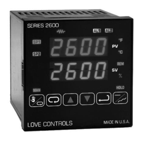
Love Controls
Love Controls 2600 SERIES instructions

Panasonic
Panasonic WVCU161C - SYSTEM CONTROLLER operating instructions

Smart-M
Smart-M StretcherPro-HD user manual
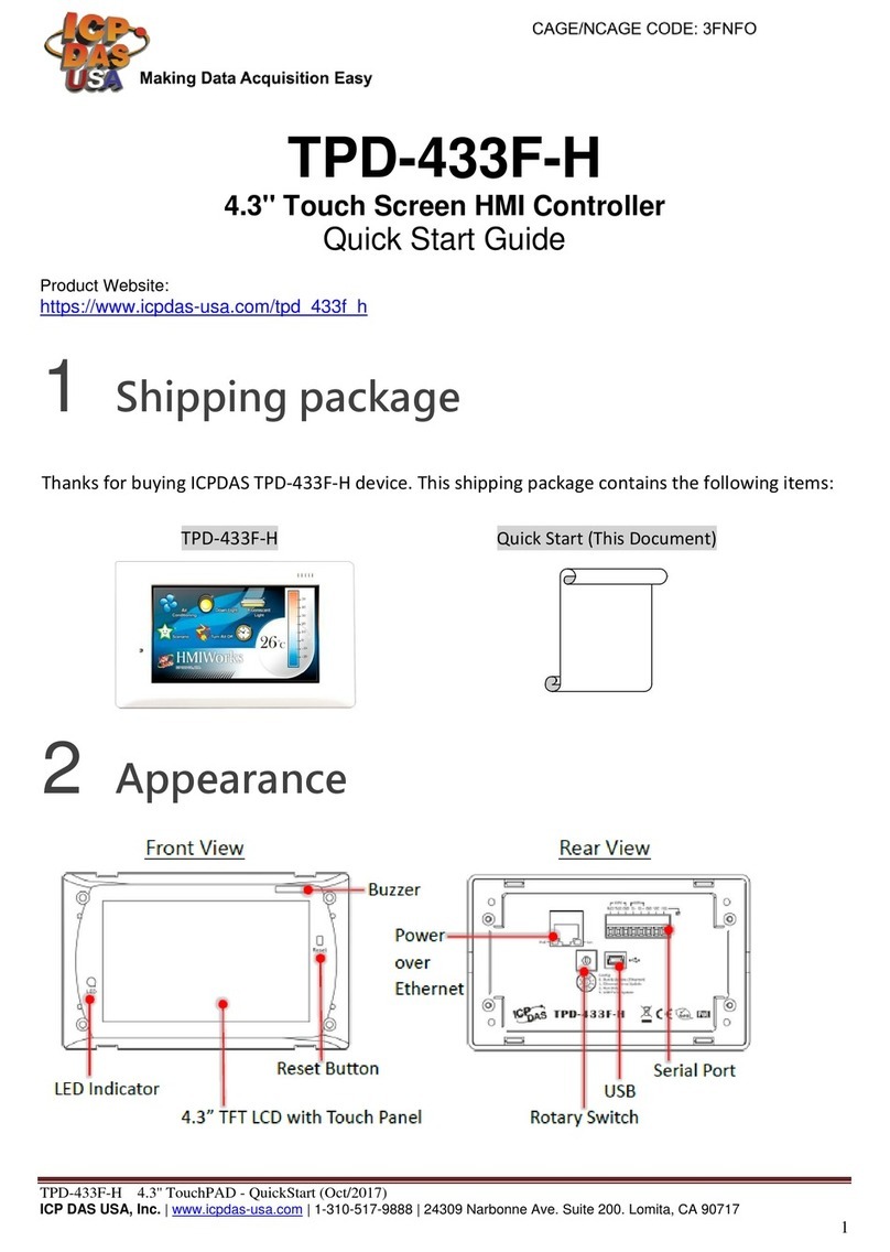
ICPDAS
ICPDAS TPD-433F-H quick start guide
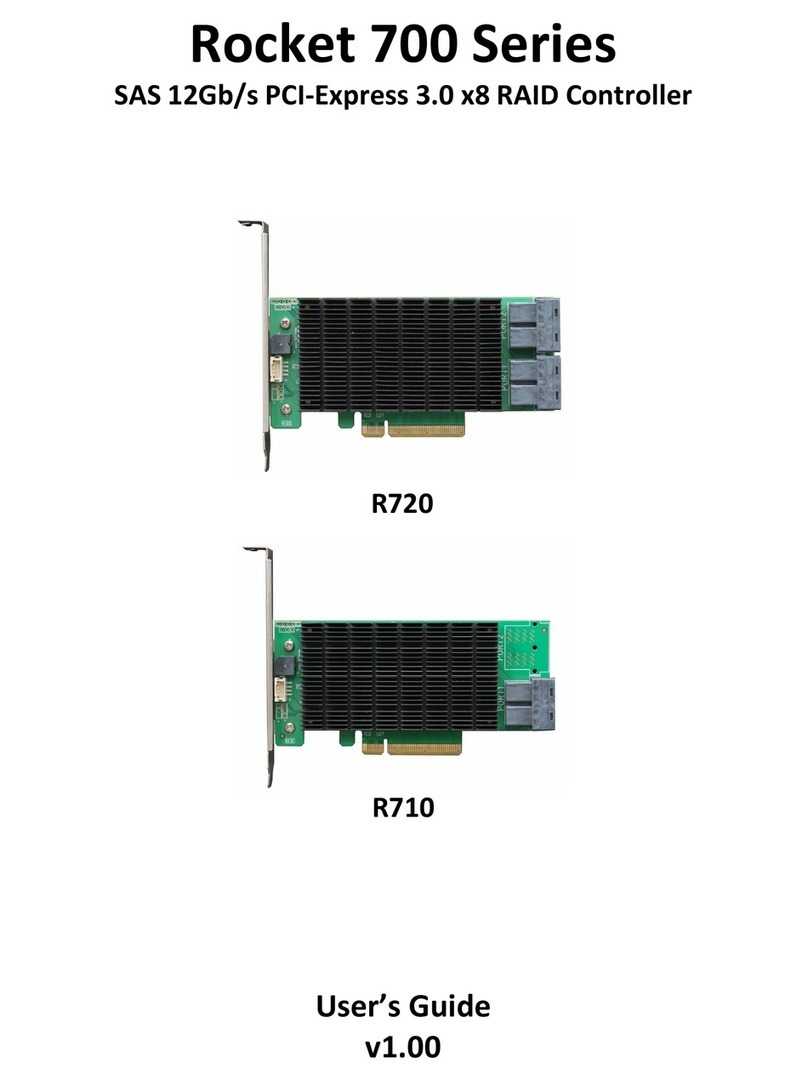
HighPoint
HighPoint Rocket 700 Series user guide
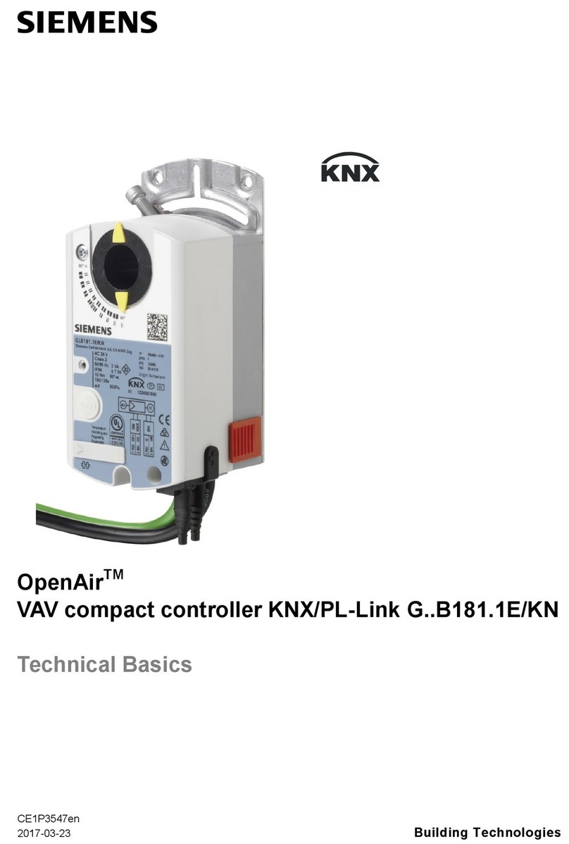
Siemens
Siemens OpenAir G..B181.1E/KN Series Technical Basics

SSS Siedle
SSS Siedle EC 602-03 Programming instructions
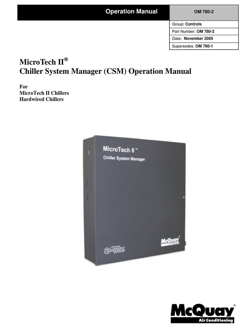
McQuay
McQuay MicroTech II Operation manual

National Instruments
National Instruments FlexRIO NI-7931R user manual

Dakota Digital
Dakota Digital PAC-2700 manual
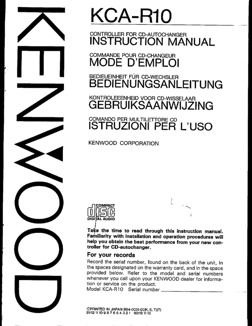
Kenwood
Kenwood KCA-R10 instruction manual
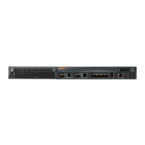
Hewlett Packard Enterprise
Hewlett Packard Enterprise Aruba 7240-US Product End-of-Life Disassembly Instructions
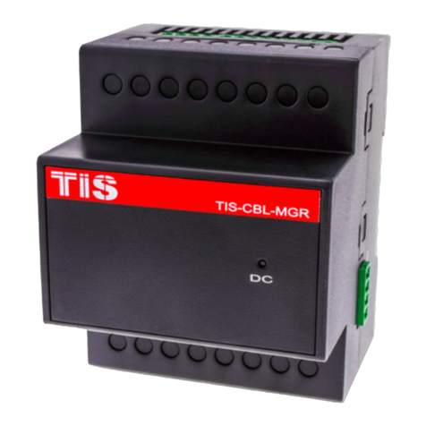
TIS
TIS TIS-CBL-MGR installation manual
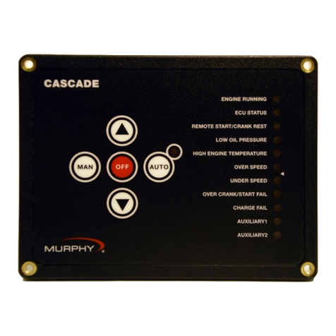
Murphy
Murphy Cascade CD101 Installation and operation manual
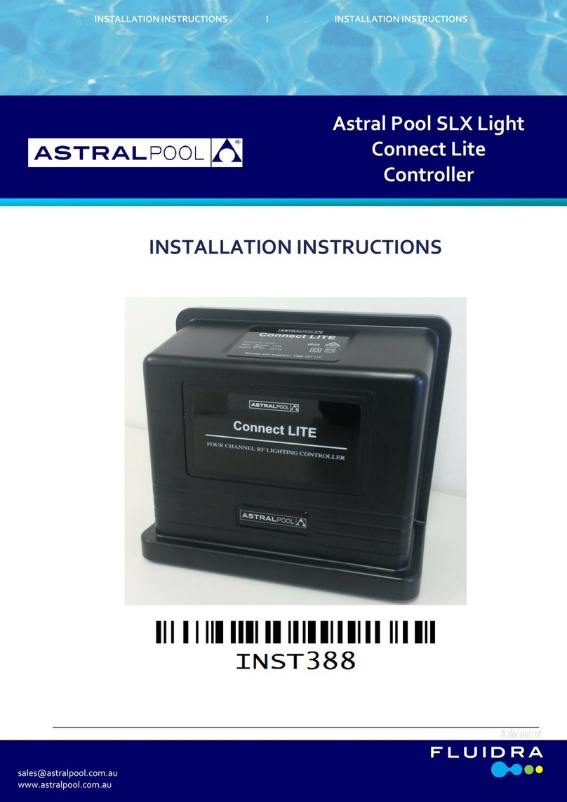
fluidra
fluidra Astral Pool SLX Light Connect Lite installation instructions


