Nogueira VFN-9000 User manual

NOGUEIRA
Esencial en el campo
Essential in the field
Feeder Wagon/Vagón Forrajero
VFN-9000
INSTRUCTIONS MANUAL
MANUAL DE INSTRUCCIONES


3
1 - Introduction
It is a top-notch quality product, especially designed to meet your needs.
Nogueira S/A is always at your disposal to answer any questions or doubts
and supply efficient and permanent technical support.
Congratulations for your purchase of the .VFN-9000 Feeder Wagon
This manual contains operating and maintenance instructions, when properly
abided by it assures good operation, safety, and durability to your
Nogueira. We recommend carefully reading it, before beginning to operate
the machine.
VFN-9000
This information is extremely important to identify your machine, in cases
when you need technical support or replacement parts.
Dear Owner
There is an identification plate fastened on the machine, which displays the
manufacturing serial number. Write this number, in the end of this manual.
The images displayed in this manual are only for illustrative purposes. Thus to facilitate your
viewing, the images show cutaway or the safety shielding removed to display it more clearly. Do
not operate the machine under any circumstances without these respective protective shields.
The reproduction of this manual is not allowed except when previous written permission is granted
by the Nogueira Indústria e Comércio de Implementos e Máquinas Agrícolas S.A.

Contents
4
2.1- Safety adhesive labels 09
3- 11Forage Wagon presentation
3.1- 11Components identification
3.2- 13Operation
3.3- 14Technical specifications
4- 16Forage Wagon setup and coupling
4.2- 17Tractor head coupling
4.3- 18Cardan size adjustment
4.4- 19Checking the work angle
5- 20Operation
4.1- 16Assembly at receiving
2- 06Safety Measures
1- 03Introduction
5.1- 20Side discharge
5.2- Rear Discharge 21
6.3- PTO speed 22
7- 25Maintenance instructions
7.4- 32Level check and/or oil replacement of the transmission box and the reducer
5.3- Orientations about discharge flow 23
7.3- 30Conveying chains tension adjustment
8- Forage Wagon preservation 36
6- Tanden wheels system 24
7.7- 35Tires pressure checking
9- Troubleshooting 37
7.1- 25Grease lubrication points
7.6- 35Wagon floor preservation
7.2- 28Drive chains tension adjustment
7.5- 34Cardan schaft maintenance

5
NOGUEIRA Máquinas Agrícolas Ltda., aim is the constant update and
improvement of its products, keeping itself the right of introduce changes without
Note:
11- 39Technical Assistance
10.1- 38Wrenches size table
11.1- 39Wagon series number
11.3- 41Technical Delivery Voucher
11.2- 40Warranty Term
10- 38Additional Information
10.2- 38Torque table

2- Safety Measures
When reading the instructions manual
On operation
Also follow the recommendations of your tractor’s Manual for a safety and efficient operation
1- The Forage Wagon was exclusively developed to
transport and distribute chopped forage and silage.
2- Never use it to transport people or animals.
3- Do not allow people on the load during discharge
process and mainly during transport.
4- Never attempt to adjust or repair components with the
wagon moving.
5- Do not carry out any maintenance with the front
discharge auger or the conveyor moving.
6- To keep the control on the wagon, mainly when it is
loaded, observe the following points: tractor weight and
power, use of weights on the front and rear axles, brakes
capacity, soil adherence conditions, soil declivity etc.
7- Do not get close to drive chains when they are
moving.
6
Note:
It means that an operational or safety detail will be presented
Warning:
It means that your life or parts of your body will be in danger. Pay attention to
this symbol.

7
Transporting on roads and streets
Note:
Wagon transport with the tractor must not be done on roads and streets. Such
practice must be limited to inside the farm properties and rural zones.
Refer to the traffic department for the regulations and laws in force in your region
about the possibility or not of the transporting the machine with the tractor on
certain parts of the roads, avoiding serious troubles. Request guidance,
authorizations and procedures in writing.
On even surfaces you can use the maximum speed of the tractor. On uneven
surfaces you should reduce the speed in order to meet the safety conditions.
When the wagon is loaded, the speed must be compatible with the tractor size. The
factors mentioned in item (Operation) must be also considered when transiting on
roads.
Whenever there is need for transporting the wagon for longer distances or when there is need
for using public roads, the transport must be done on truck.
The wagon must be entirely on the truck body. It is basic that the head be fastened to the floor
of the truck body and the wheels wedged with wood wedges on the floor. Moreover, steel
cables or special ropes may be used to fasten the wagon to the truck body.
Transport on truck

8
Note:
To transport the wagon, it is also need to bend and lock the lateral unloader chute
(1), according to described below:
1- Remove the rear lock pin (2).
2- Bend the chute (1).
3- Install the front lock pin (3).
2
1
3
1

9
2.1- Safety adhesive labels
Read the instruction manual before
turning on the machine. Pay close
attention to all the operating and safety
recommendations, in order to avoid any
unexpected accidents that may occur
while operating the machine.
Turn off the tractor and remove the key
from the ignition before performing any
maintenance, adjustment, lubrication,
cleaning jobs etc., on the machine.
Thereby you will avoid any accidental
actuation and avoid dangerous
situations that may cause serious
accidents.
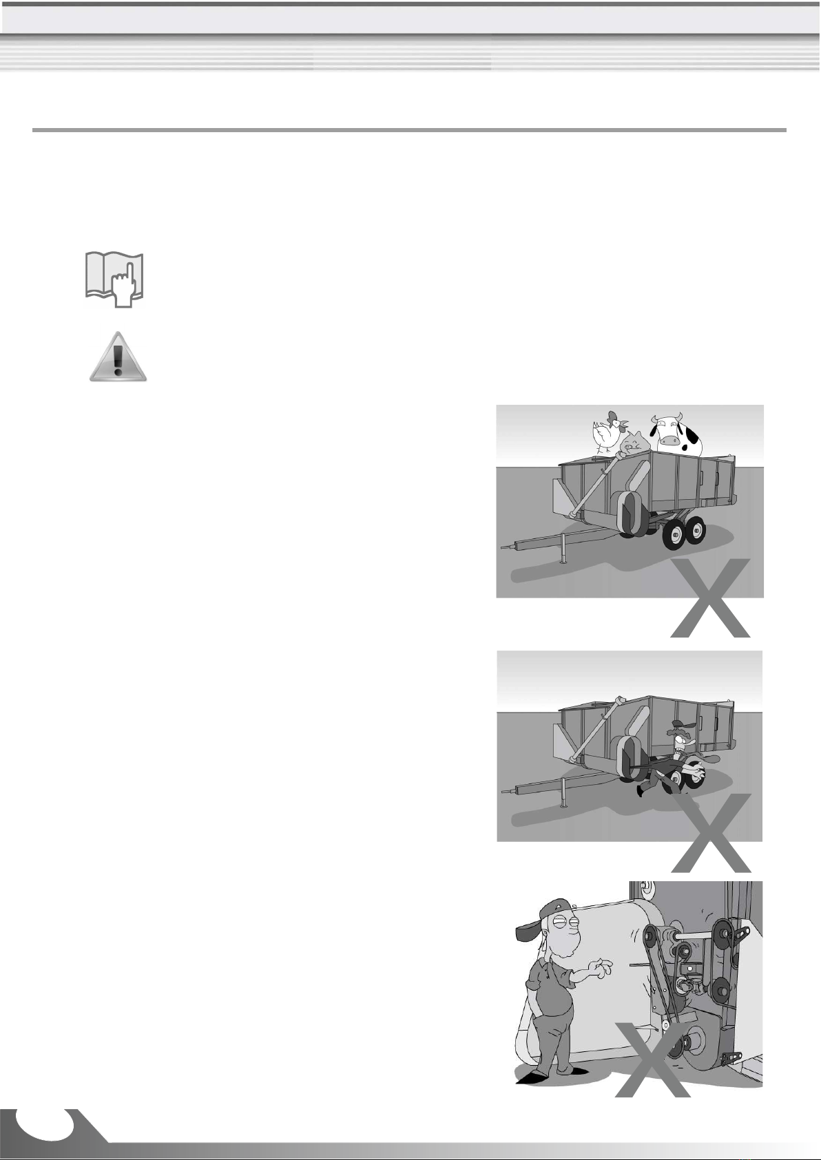
Do not stay on the machine while it is
operating or carrying loads. Sudden jolts,
starting, or stopping can cause falling,
causing an accident. Avoid all dangerous
situations.
Keep your distance and never place your
hands near the moving helix transporter,
as contact can cause a serious accident.
Do not get close to the machine until it is
completely motionless. Remember
rotating parts do not stop moving
immediately after turning the machine
off. Some parts continue moving also
unnoticeably, but you cannot see them.
Keep your hands away
from chains and other
moving parts, grabbing
t h e m a n d c a u s e
injuries.
Do not open or remove
covers or safety shields
from the machine when
it is operating.

Keep away from the articulating area,
between the machine and the tractor.
Sideway movements from the machine
can hit you and cause an accident.
Keep your distance
and never place your
han ds n e ar t he
m o v i n g h e l i x
t r a n s p o r t e r, a s
contact can cause a
serious accident.
Careful with wagon
tailgate, risk of
c r u s h i n g t h e
fingers or hand.
Never enter into an
area of crushing as
long as parts may
move.
When operating the harvester, wear
personal protective equipment (PPE).
Prolonged exposure to noise, without
noise protection can cause hearing loss.
This displays the RPM (revolutions per
minute) and the rotation direction of the
power take-off.
Never enter in the wagon when it is
turned on, risk of accident with contact
with the conveyors, transporting screws
or drums when moving.
2.1- Safety adhesive labels
10

11
3- Forage Wagon presentation
3.1- Components identification
2- Head
4- Full plating
1- Coupling terminal
3- Stand jack
5- Compartment of the driving system of
the top unrolling device
6- Driving cardan
4
11
7
10321
6
5
9
8
8- Unrolling device
9- Conveyor
10- Side outlet chute
7- TANDEN wheel assembly
11- Rear outlet door

12
17- Gearbox (it drives the unroalling devices - 8)
15- Auger driving gear
13- All components driving gear, in case of forage side unloading
14- All components driving gear, in case of forage rear unloading
16- Moto-reducer (it drives the conveyor - 9)
13
14
15
16
17

13
3.2- Operation
Note:
Whenever the terms ¨left¨ and ¨right¨ are used, it is considered the tractor’s
operating cab as reference point
Forage wagon is an equipment addressed to silage transport and also to carrying out
unloading of silage in the through or silo. Its project aims quickness and efficiency in such
applications.
The conveying chains system takes the silage load towards the auger that, in turn, performs
the discharge.
Conveyor speed, towards front discharge, depends on the product that is being discharge
and can be adjusted with the tractor acceleration. However, for the discharge by the rear
door, the speed is constant, depending only on the tractor PTO rotation.
To carry out the rear discharge, it is need only to manually unlock the door and invert the
transmission system pins (see page 2 ).0
Lateral esquerda
LH side

14
Total height (A) ................................... ....................................... ........................... 2.580 mm
Total width (L1) ............................................. .................................. ...................... 2.500 mm
Width for transport (L2) ................................ .................................. ....................... 2.200 mm
Total length (C) ........................................... ................................... ....................... 6.680 mm
Front discharge flow .............................................. ........................... 2,5m³/ minute ..............
Wheels system ........................................................ ....................... ........................ TANDEN
Chute height ............................................... ..................................... ........................ 750 mm
Approximated weight (empty) ............................ .................................... ................. 2.200 kg
Rear discharge time ............................................ .. ............................ . ................... 2 minutes
Required power .................................................... ...................... ................................. 50 cv
Volume ......................................................... ............................ 9 m³ .....................................
Tires ................................................................... ................................... 10.5/65x16 ..............
Size .............................................................. ................................... ..................... 2.000 mm
Tires pressure ...................................................... ................................ ....................... 50 lbs
3.3- Technical specifications

15
L1 L2
C
A

16
In normal conditions, the wagon is transported with the head (1) assembled. However, if
because of technical reasons you have to remove it, assemble it according to instructions
below:
Note:
Coupling should be done on a flat and even
place.
4- Forage Wagon setup and coupling
4.1- Assembly at receiving
b) Align the head ends holes with wagon coupling
points holes. Ask the aid of another person to turn the
operation easier.
a) Put the head on the ground, on a proper wooden
wedge.
c) Install the two pins (2) fastening the head ends to the
wagon. Install the counter-pins (2a).
d) Install the two gastening screws (3) of the chassis.
e) Using a proper wrench, tighten the nuts (4).
1
22
2a
1
4
3

17
NOTE: Tractor draw-bar must have head (according to
illustrated), preventing the wagon from raising up.
c) Install the coupling pin (4) and lock it with a counter-
pin, preventing accidental uncoupling.
To couple the head to the tractor, follow the instructions
below:
a) Approximate the tractor aligning the draw-bar (1) with
the coupling terminal (2) of the wagon.
b) In case there is need, lower or rise the head through
the stand jack (3).
d) Pull the locking pin (5) and put the stand-jack (3) in
horizontal position. After that, reinstall the pin to lock the
stand-jack.
NOTE: When the machine is running, the stand-jack
should be in work position (horizontal).
e) Check the wagon leveling and adjust as needed,
according to described in the previous page.
4.2- Tractor head coupling
Coupling should be done on a flat and even
place
Note:
3
5
1
4
2

18
Tractor
3 cm
3 cm
Wagon
1
2
Checking and adjusting the cardan length
f) With a file, remove the saw burrs resulting from the
cuts.
g) Apply grease in the internal end of the tube and on
the cardan bar.
h) Assemble all cardan components again.
c) Disassemble the cardan. Couple the tube (1) to the
PTO and the bar (2) to the wagon.
e) If the gap is less than mentioned or does not exist at
all, mark and cut the tube (1) and the bar (2) as welll as
the protecting tube (3), all in the same proportion
(measurement).
a) Uncouple the cardan shaft from the wagon.
a) Couple the wagon to the tractor.
b) Follow the instructions of the item ¨Cardan shaft
maintenance¨ in page 3 , to remove the protecting
shield
4
d) Join the parts of the cardan side by side and check
whether there is a minimum gap of 3 cm in each end.
At the first coupling, check whether the cardan shaft is
with the proper length. For that, follow the instructions
below:
Removing the cardan protecting shield
b) Move the tractor in a such way to get one of the rear
tires as close as possible to the head.
4.3- Cardan size adjustment
Cardan shaft with protection shield

19
4.4- Checking the work angle
The angle 0º is the center line of the tractor. The most angle allowed to the cardan, when it is
being driven by the TDP, is 15º. In case it exceeds this value (example: maneuvers), turn off
the PTO.
The figure illustrated the most inclination angle allowed to the cardan, with the wagon moving
and the TDP running: 15º. In case the TDP is not running, the most angle is 30º.
Note:
With the TDP ¨turned off¨, the cardan shaft angle in maneuvers can reach at most
30º.
15º

20
Note:
In case it is difficult to introduce the screw,
turn the cardan (6) untill the holes of the gear
(5) and the cardan (7) match, turning the
fitting easier.
5- Operation
Side discharge settings:
A- Side discharge
Observe belt behavior and adjust speed by varying
power take-off speed.
Forage Wagon leaves the factory with the side
discharge, what allows the forage discharge by the
auger. Move the tractor at a speed compatible with the
discharge flow rate for even distribution.
NOTE: There should be never a screw on the gear (6)
when the conveyor is turning frontward.
5.1- Side discharge:
2
6
5
4
a) Install the screw (1) on the gear (2);
b) Install the screw (3) on the gear (4);
c) Remove the screw (5) on the gear (6);
Table of contents
Languages:
Popular Tractor Accessories manuals by other brands

Tiger
Tiger JD6M MY20 Mounting and operating instructions

HOLMS
HOLMS TKH Operator's instruction

Tiger
Tiger BENGAL JD6110-30M/R T4F Mounting and operating instructions

Homelite
Homelite LM-991013 Instructions-parts list

MK Martin
MK Martin Pulsar Wing Operator's & parts manual

Alamo
Alamo Schulte SRW 1400 OPERATOR’S MANUAL WITH PARTS LISTING