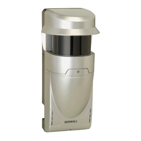
nologo ZOOM-Z2E User manual

Fotodispositivo infrarosso
Infrared photocell
Photocellule
Infrarot Lichtschranke
Fotocélula
ZOOM-Z2E / IR5001PS
ZOOM-Z1i / IR6000IS
ZOOM-Z3E
ZOOM-Z4E
FIRE-FE
LOOK-FE
LOOK-FEmini
Istruzioni ed avvertenze
Instructions et notices d’emploi
Instructions and warnings
Bedienungsanleitung und Warnungen
Instrucciones y advertencias
1 2 3 123 456
TX RX
abilita sincronismo solo 12/24Vac
activate the synchronisation only 12/24Vac
active la synchronisation 12/24Vac
aktiviert den Synchronismus nur 12/24Vac
permite sincronizar solo 12/24Vac
NC
12 / 24 Vac/dc
12 Vac/dc
NO
24 Vac/dc
_
+
+
12 / 24 Vac/dc
12 Vac/dc
24 Vac/dc
_
+
+
4 = Comune
5 = N.C. allineate (LED spento)
6 = N.A. allineate (LED spento)
4 = commun
5 = N.F. aligné (LED étéint)
6 = N.O. aligné (LED étéint)
4 = common
5 = N.C. in line (LED o)
6 = N.O. in line (LED o)
4 = gemein
5 = N.C. in Reihe (LED aus)
6 = N.O. in Reihe (LED aus)
4 = Común
5 = N.C. en alineación (LED apagado)
6 = N.A. en alineación (LED apagado)
MAX MIN
Potenza segnale
Power signal
Puissance signal
Signalstärke
Potencia de la señal
JS JS
4 5
NC
NO
JS
RX
v.1 v.2
JS
LED
RX
alimentazione / power supply / alimentation /
Stromversorgung / alimentación Vac/dc 12 / 24
Portata / max. range up / portée / Reichweite
/ alcance m20
Temperatura di funzionamento / Operating
temperature Température de fonctionnement
/ Betriebstemperatur
- 10 °C
+ 60 °C
assorbimento TX / TX power absorption /
consommation TX / Stromverbrauch TX /
consumo TX
mA 25
assorbimento RX / RX power absorption /
consommation RX / Stromverbrauch RX /
consumo RX
mA 35
contatto relè di uscita / output relay contact /
type de relais / Relaistyp / tipo de relé
max 500mA
e 48Vac/dc
grado di protezione / protection / Schutzart IP 55 EN 60529
Caratteristiche tecniche /
Technical features / Caractéristiques techniques /
Technische Eigenschaften / Características técnicas
Z2E-Z1i-Z3E-Z4E-FE_17x24_020322_VXX19_IT-GB-FR-DE-ES www.ebtechnology.it www.nologo.info

• IT Installazione: Per aprire la fotocellula sollevare il frontale della fotocellula verso l’esterno. Inlare i cavi nell’apposita sede e ssare la basetta
alla parete. Se si deve ssare la fotocellula al muro, eettuare i tre fori ø 5 ed innestare tasselli adeguati. Se si deve ssare la fotocellula su metallo,
eettuare i tre fori ø 3 per predisporre l’utilizzo delle sole viti autolettanti. Eettuare i collegamenti. Fissare le fotocellule e alimentarle con tensione
compresa tra 12 e 24 V cc/ca. Se il posizionamento, l’allineamento ed il collegamento sono eseguiti correttamente, il LED rosso sul ricevitore sarà
spento. Ogni qualvolta si interrompe il raggio, il LED rosso si accende. Coprire la fotocellula con il frontale; inserire a battuta e chiudere agganciando
dall’alto verso il basso. Interrompere il raggio più volte vericando la risposta del relè. Fissare i frontali con le viti in dotazione.
• GB Installation: To open the photocell, lift the front panel of the photocell. Insert the cables in their housing and x the base to the wall. If the photocell
has to be mounted on a wall, drill the trhree 5 ø holes and t suitable screw anchors. If the photocell has to be mounted on metal, drill the three 3 ø
holes for tting with the self_tapping screws. Make the connections. Power the photocells with a voltage between 12 and 24V DC/AC. If positioning,
alignment and connection have been carried out properly, the red LED on the receiver will be o. Each time the ray is interrupted, the red LED switches
on. Cover the photocell with the front panel. Insert to the stop and close it. Interrupt the ray several times checking the relay response. Fix the front
panels with the provided screws.
• FR Installation: Pour ouvrir la cellule, soulever le panneau vers l’extérieur. Enlez les câbles dans le logement prévu et xer l’embase au mur. Pour
xer la cellule photo-électrique à une paroi, percer les trois trous ø 5 et positionner les goujons appropriés. Pour la xer sur un support métallique,
percer les trois trous ø 3 pour l’utilisation des vis-tarauds. Eectuer les branchements. Alimenter les cellules avec une ten-sion entre 12 et 24V CC/
CA. Si les opérations de positionnement, d’alignement et de branchement ont été bien eec-tuées, le LED rouge présent sur le récepteur sera éteint.
Lorsque le faisceau est iinterrompu, le LED rouge s’allume. Placer le panneau frontale sur la cellule photo-électrique pour la couvrir, l’insérer jusqu’à
quand il s’arrête et le fermer. Interrompre le faisceau plusieurs fois pour contrôler la réponse du relais. Fixer les panneaux frontales avec les vis
fournies.
• DE Die Installation: Um die Infrarot Lichtschranke zu önen, die Vorderseite der Lichtschranke nach außen anheben. Stecken Sie die Kabel
hinein und machen Sie den unteren Teil der Lichtschranke fest. Wenn die Lichtschranke an die Wand festgemacht werden soll, dann machen Sie
3 Bohrungen von ø 5 und fügen Sie die geeigneten Dübel hinein. Wenn die Lichtschranke auf Metall festgemacht werden soll, dann machen Sie 3
Bohrungen von ø 3 um die Benutzung der selbstschneidenden Schrauben vorzubereiten. Machen Sie die Verbindungen. Legen sie die Lichtschranke
fest und geben Sie Stromversorgung 12 und 24 V ac/dc. Wenn die Lichtschranken richtig positioniert sind, dann schaltet sich das rote L.e.d im
Empfänger ein. Wenn die Strahlen unterbrochen werden, das schaltet sich das rote L.E.D. ein.Decken die vordere Seite der Lichtschranke ab und
schließen Sie die Lichtschranke zuerst oben dann unten. Unterbrechen Sie den Strahlen mehrmals und prüfen Sie die Relay Reaktion. Die vorderen
Teile mit den gelieferten Schrauben xieren.
• ES Instalación: Para abrir la ZOOM-Z2E/FIRE-FE, elevar el elemento frontal de la fotocélula. Introducir los cables en la especica sede y jar la
base a la pared. En caso de jarse la fotocélula en la pared, practicar los tres agujeros ø 5 e introducir tacos adecuados. Si se debe jar la fotocélula
sobre metal, practicar los tres agujeros ø 3 para predisponer el uso de los tornillos autorroscantes. Efectuar las conexiones. Alimentar las fotocélulas
con tensión comprendida entre 12 y 24V CC/CA. Si la coloración, alineación y conexión se efectúan de modo correcto, el LED rojo en el receptor
permanece apagado. Cada vez que se interrumpe el rayo, el LED rojo se enciende. Cubrir la fotocélula con su elemento frontal. Interrumpir el rayo
varias veces vericando la respuesta del relé. Fijar los frontales con los tornillos suministrados adjuntos.
1 2 341 2 3
TX 1 RX 1
• abilitare sincronismo solo 12/24Vac
• activate the synchronisation only 12/24Vac
• active la synchronisation 12/24Vac
• aktivierung Synchronismus nur beim 12/24Vac
• permite sincronizar solo 12/24Vac
sincronismo
synchronisation
synchronisation
synchronismus
sincronizar solo
1 2 341 2 3
TX 2 RX 2
! 12 / 24 Vac
65 65
100%
ITALY
JS JS JS JS
Dichiarazione CE conformità / EC declaration of conrmity / EG-Konformitatserklarung /
Déclaration CE de conformité / Declaracion CE de conformidad
ZOOM-Z2E / IR 5001 PS ZOOM-Z1i / IR 6000 IS ZOOM-Z3E ZOOM-Z4E LOOK-FE LOOK-FEmini FIRE-FE
è conforme alle seguenti disposizioni pertinenti: complies with thefollowing relevantprovisions: folgenden einschlagigen Bestimmungen entspricht:
correspondaux dispositions pertinentes suivantes: sotisface las disposiciones pertinentessiguientes:
2014/30/UE, 2014/35/UE
This manual suits for next models
8
Other nologo Security Sensor manuals


