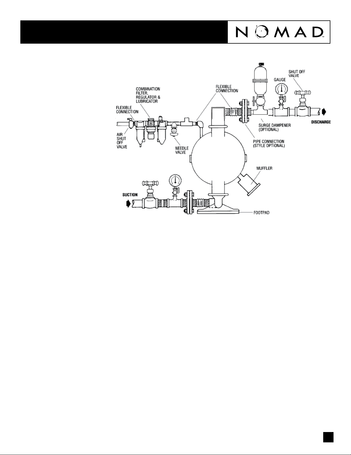
SUGGESTED INSTALLATION
NTG40 NOMAD TRANS-FLO™
The suction pipe size should be at least 38mm
(1 – 1/2") diameter or larger if highly viscous
material is being pumped. The suction hose
must be non-collapsible, reinforced type as
the NTG40 is capable of pulling a high vacuum.
Discharge piping should be at least 32mm
(1 – 1/4"); larger diameter can be used to reduce
friction losses. It is critical that all ttings and
connections are airtight or a reduction or loss of pump
suction capability will result.
Every pump location should have an air line large
enough to supply the volume of air necessary to
achieve the desired pumping rate.
Unnecessary elbows, bends and ttings should be
avoided. Pipe sizes should be selected so as to keep
friction losses within practical limits. All piping should
be supported independently of the pump.
Expansion joints can be installed to aid in absorbing
the forces created by the natural reciprocating action
of the pump. Flexible connections between the pump
and rigid piping will also assist in minimizing pump
vibration. A surge suppressor should be installed to
protect the pump, piping and gauges from surges and
water hammer.
When pumps are installed in applications involving
ooded suction or suction head pressures, a gate
valve should be installed in the suction line to permit
closing of the line for pump service.
The NTG40 can be used in submersible applications
only when both wetted and non-wetted portions are
compatible with the material being pumped. If the
pump is to be used in a submersible application, a
hose should be attached to the pump’s air exhaust
and the exhaust air piped above the liquid level.
5
PERFORMANCE
NTG40 METAL
PTFE-FITTED
Flow rates indicated on chart were determined by pumping water.
For optimum life and performance, pumps should be specied so that daily operation parameters
will fall in the center of the pump performance curve.
Height...............................442 mm (17.4")
Width ...............................391 mm (15.4")
Depth ...............................285 mm (11.2")
Est. Ship Weight .......Aluminum 17 kg (38 lbs)
316 S.S. 26 kg (57 lbs)
Ductile Iron 22kg (49 lbs)
Air Inlet................................ 13 mm (1/2")
Inlet................................. 38 mm (1-1/2")
Outlet ............................... 32 mm (1-1/4")
Suction Lift ........................ 2.74 m Dry (9')
8.53 m Wet (28')
Displacement/Stroke......... 0.53 l (0.14 gal.) 1
Max. Flow Rate ................ 235 Ipm (62 gpm)
Max. Size Solids .................. 4.8 mm (3/16")
1Displacement per stroke was calculated at 4.8
bar (70 psig) air inlet pressure against a 2 bar
(30 psig) head pressure.
Example: To pump 94.6 lpm (25 gpm) against
a discharge pressure head of 2.7 bar (40 psig)
requires 4.1 bar (60 psig) and 51 Nm3/h (30
scfm) air consumption. (See dot on chart.)
Caution: Do not exceed 8.6 bar (125 psig) air
supply pressure.