nomad NTG40 TRANS-FLO User manual

1/14, Rev. 3
NTG40 NOMAD TRANS-FLO™
OPERATION MANUAL
AIR-OPERATED •DOUBLE DIAPHRAGM •PUMPS
A JDA Global Company
ALUMINUM Models
316 S.S. Models

CAUTION – SAFETY POINTS
NTG40 NOMAD TRANS-FLO™
TEMPERATURE LIMITS:
Neoprene -17.8°C to 93.3°C 0°F to 200°F
Buna-N -12.2°C to 82.2°C 10°F to 180°F
EPDM -51.1°C to 137.8°C -60°F to 280°F
Viton®-40°C to 176.7°C -40°F to 350°F
Santoprene®-40°C to 107.2°C -40°F to 225°F
Polyurethane 12.2°C to 65.6°C 10°F to 150°F
Hytrel®-28.9°C to 104.4°C -20°F to 220°F
PTFE 4.4°C to 104.4°C 40°F to 220°F
1
1. Review the NOMAD Chemical Field Guide
for all applications. The information
provided is the “best thinking available”
regarding chemical compatibility. The
guide however, does not provide a
recommendation.
2. Always wear safety glasses during pump
operation. A diaphragm rupture may force
liquid to exit via air exhaust.
3. Whenhandlingammableuids,prevent
static sparking by properly grounding
the pump.
4. Do not exceed 125 psig (8.6 bar).
5. Prior to maintenance, compressed air
line should be disconnected to allow air
pressure to bleed from pump.
6. Tighten all clamp bands and hardware
parts prior to installation. Fittings may
loosen during transportation.

PUMP DESIGNATION SYSTEM
NTG40 NOMAD TRANS-FLO™
MATERIAL CODES
MODEL
NT40 = 38MM (1 – 1/2")
WETTED PARTS &
OUTER PISTON
AA = ALUMINUM / ALUMINUM
S = 316 S.S.
AIR CHAMBERS
P = POLYPROPYLENE
(CENTER SECTION)
CENTER BLOCK
P = POLYPROPYLENE
AIR VALVE
B = BRASS
DIAPHRAGMS
BN = BUNA-N (Red Dot)
FG = HYTREL
ND = EPDM (Blue Dot)
NE = NEOPRENE (Green Dot)
SN = SANTOPRENE
TF = PTFE
VT = VITON
VALVE BALL
BN = BUNA-N (Red Dot)
FS = HYTREL
ND = EPDM (Blue Dot)
NE = NEOPRENE (Green Dot)
SN = SANTOPRENE
TF = PTFE (White)
VALVE SEAT
A = ALUMINUM*
S = STAINLESS*
BN = BUNA-N (Red Dot)
FG = HYTREL
ND = EPDM (Blue Dot)
NE = NEOPRENE (Green Dot)
SN = SANTOPRENE
VT = VITON
*Valve seat o-ring required.
VALVE SEAT O-RING
TF = PTFE
2
NTG40 / XXXX / XX / XX / XX / X
MODEL VALVE SEAT
THREADED CONNECTION
VALVE BALLS
DIAPHRAGMS
AIR VALVE
CENTER BLOCK OR CENTER SECTION
AIR CHAMBERS OR CENTER SECTION
WETTED PARTS
SIZE
38 mm (1 – 1/2") Pump
Maximum Flow Rate:
307 lpm (81 gpm)

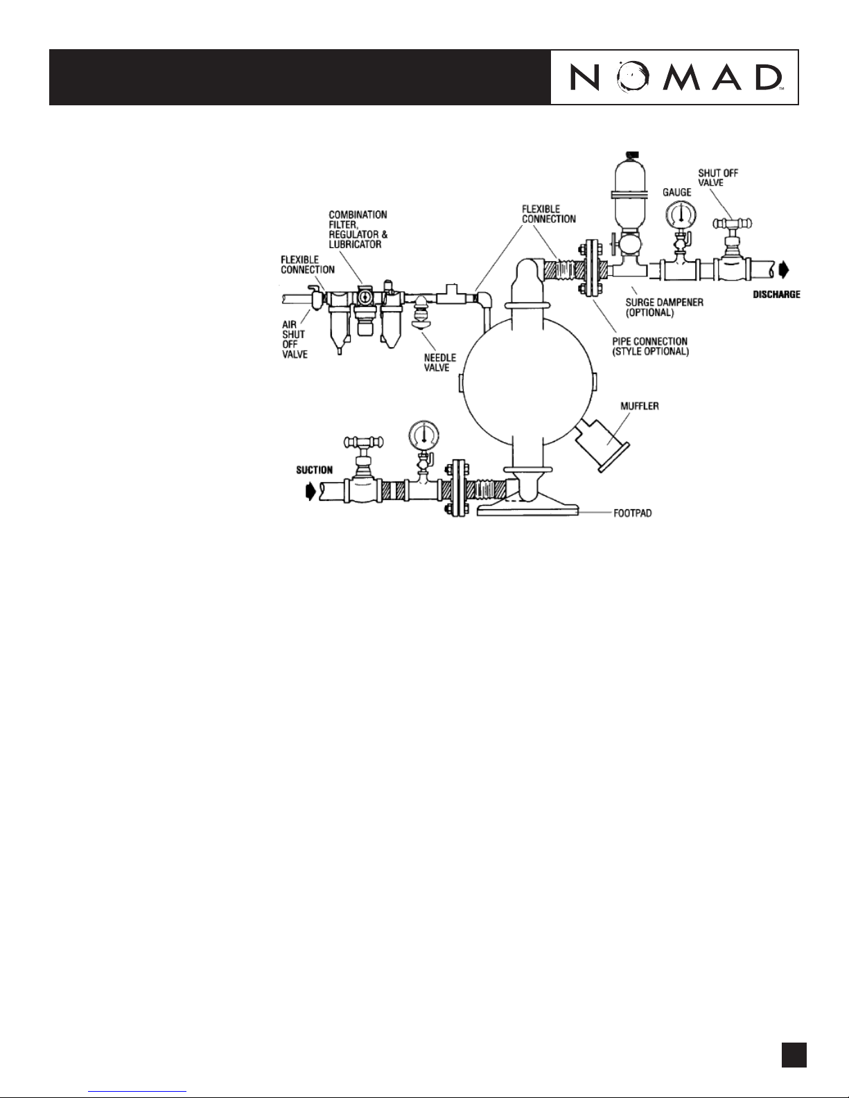
AIR OPERATED DOUBLE DIAPHRAGM PUMPS
FUNCTIONALITY AND FLOW PATTERN
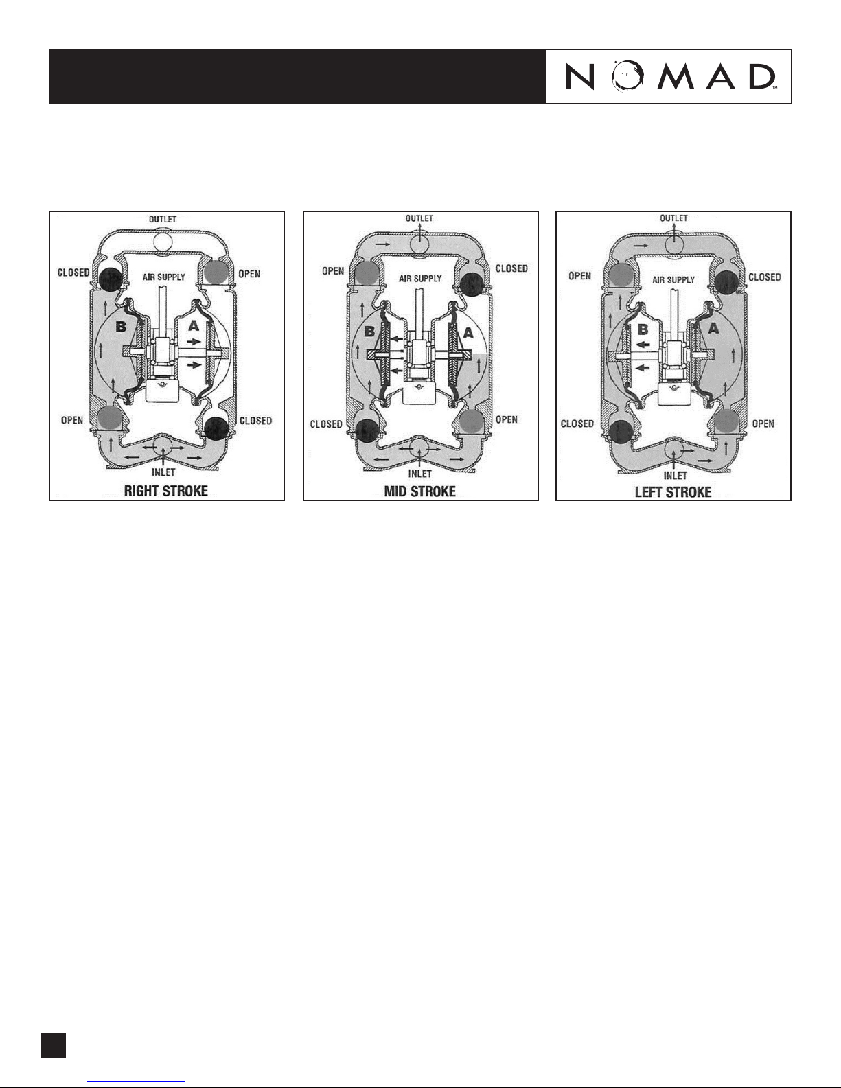
Figure 1: Air valve directs
pressurized air to the back side
of diaphragm A. Compressed air
is applied directly to the liquid
column separated by elastomeric
diaphragms. The diaphragm
acts as a separation membrane
between the compressed air
and liquid, balancing the load
and removing mechanical
stress from the diaphragm. The
opposite diaphragm is pulled
in by the shaft connected to
the pressurized diaphragm.
Diaphragm B is on its suction
stroke; air behind the diaphragm
has been forced out to the
atmosphere through the exhaust
port of the pump. Atmospheric
pressure forces uid into the
inlet manifold forcing the inlet
valve ball o its seat. Liquid is
free to move past the inlet valve
ball and ll the liquid chamber
(see shaded area).
Figure 2: When the pressurized
diaphragm, diaphragm A,
reaches the limit of its discharge
stroke, the air valve redirects
pressurized air to the back
side of the diaphragm B. The
pressurized air forces diaphragm
B away from the center block
while pulling diaphragm A to
the center block. Diaphragm B
is now on its discharge stroke.
These same hydraulic forces
lift the discharge valve ball o
its seat, while the opposite
discharge valve ball is forced
ontoitsseat,forcinguidtoow
through the pump discharge.
Atmospheric pressure forces
uid into the inlet manifold of
the pump. The inlet valve ball is
forced o its seat allowing the
uid being pumped to ll the
liquid chamber.
Figure 3: At completion of
the stroke, the air valve again
redirects air to the back side
of diaphragm A, which starts
diaphragm B on its exhaust
stroke. As the pump reaches
its original starting point, each
diaphragm has gone through
one exhaust and one discharge
stroke. This constitutes one
complete pumping cycle. The
pump may take several cycles to
completely prime depending on
the conditions of the application.
NTG40 NOMAD TRANS-FLO™
3

BSP threads available.
DIMENSIONAL DRAWINGS
PERFORMANCE
NTG40 METAL
RUBBER-FITTED
NTG40 NOMAD TRANS-FLO™
4
Height............................................. 442 mm (17.4")
Width.............................................. 391 mm (15.4")
Depth ............................................. 285 mm (11.2")
Est. Ship Weight.................Aluminum 17 kg (38 lbs)
316 S.S 26 kg (57 lbs)
Air Inlet...............................................13 mm (1/2")
Inlet................................................ 38 mm (1-1/2")
Outlet ............................................. 32 mm (1-1/4")
Suction Lift .................................... 5.49 m Dry (18')
8.53 m Wet (28')
Displacement/Stroke ................... 1.02 l (0.27 gal.) 1
Max. Flow Rate ............................ 288 Ipm (76 gpm)
Max. Size Solids...............................4.8 mm (3/16")
1Displacement per stroke was calculated at 4.8 bar
(70 psig) air inlet pressure against a 2 bar (30 psig)
head pressure.
Example: To pump 113.6 lpm (30 gpm) against
a discharge pressure head of 2.7 bar (40 psig)
requires 4.1 bar (60 psig) and 25.5 Nm3/h (15 scfm)
air consumption. (See dot on chart.)
Caution: Do not exceed 8.6 bar (125 psig) air
supply pressure.
Flow rates indicated on chart were determined by pumping water.
For optimum life and performance, pumps should be specified so that daily operation parameters
will fall in the center of the pump performance curve.
DIMENSIONS
ITEM METRIC (mm) STANDARD (inch)
A 391 15.4
B 63 2.5
C 219 8.6
D 442 17.4
E 285 11.2
F 338 13.3
G 224 8.8
H 152 6.0
J 193 7.6
K 67 2.6
L 11 0.4

SUGGESTED INSTALLATION
NTG40 NOMAD TRANS-FLO™
The suction pipe size should be at least 38mm
(1 – 1/2") diameter or larger if highly viscous
material is being pumped. The suction hose
must be non-collapsible, reinforced type as
the NTG40 is capable of pulling a high vacuum.
Discharge piping should be at least 32mm
(1 – 1/4"); larger diameter can be used to reduce
friction losses. It is critical that all ttings and
connections are airtight or a reduction or loss of pump
suction capability will result.
Every pump location should have an air line large
enough to supply the volume of air necessary to
achieve the desired pumping rate.
Unnecessary elbows, bends and ttings should be
avoided. Pipe sizes should be selected so as to keep
friction losses within practical limits. All piping should
be supported independently of the pump.
Expansion joints can be installed to aid in absorbing
the forces created by the natural reciprocating action
of the pump. Flexible connections between the pump
and rigid piping will also assist in minimizing pump
vibration. A surge suppressor should be installed to
protect the pump, piping and gauges from surges and
water hammer.
When pumps are installed in applications involving
ooded suction or suction head pressures, a gate
valve should be installed in the suction line to permit
closing of the line for pump service.
The NTG40 can be used in submersible applications
only when both wetted and non-wetted portions are
compatible with the material being pumped. If the
pump is to be used in a submersible application, a
hose should be attached to the pump’s air exhaust
and the exhaust air piped above the liquid level.
5
PERFORMANCE
NTG40 METAL
PTFE-FITTED
Flow rates indicated on chart were determined by pumping water.
For optimum life and performance, pumps should be specified so that daily operation parameters
will fall in the center of the pump performance curve.
Height............................................. 442 mm (17.4")
Width.............................................. 391 mm (15.4")
Depth ............................................. 285 mm (11.2")
Est. Ship Weight.................Aluminum 17 kg (38 lbs)
316 S.S. 26 kg (57 lbs)
Air Inlet...............................................13 mm (1/2")
Inlet................................................ 38 mm (1-1/2")
Outlet ............................................. 32 mm (1-1/4")
Suction Lift ...................................... 2.74 m Dry (9')
8.53 m Wet (28')
Displacement/Stroke ................... 0.53 l (0.14 gal.) 1
Max. Flow Rate ............................ 235 Ipm (62 gpm)
Max. Size Solids...............................4.8 mm (3/16")
1Displacement per stroke was calculated at 4.8 bar
(70 psig) air inlet pressure against a 2 bar (30 psig)
head pressure.
Example: To pump 94.6 lpm (25 gpm) against
a discharge pressure head of 2.7 bar (40 psig)
requires 4.1 bar (60 psig) and 51 Nm3/h (30 scfm) air
consumption. (See dot on chart.)
Caution: Do not exceed 8.6 bar (125 psig) air
supply pressure.

6
Note: In the event of a power
failure,theshutovalveshould
be closed, if the restarting of
the pump is not desirable once
power is regained.
TROUBLESHOOTING
NTG40 NOMAD TRANS-FLO™
Pump will not run or runs slowly.
1.Checkairinletscreenandairlterfordebris.
2.Checkforstickingairvalve,ushairvalve
in solvent.
3. Check for worn out air valve. If piston face in air
valve is shiny instead of dull, air valve is worn
beyond working tolerances and must
be replaced.
4. Check center block rings. If worn excessively, they
willnotsealandairwillsimplyowthroughpump
and out air exhaust.
5. Check type of lubricant being used.
ISO 15-5 wt. recommended.
Pump runs but little or no product ows.
1. Check for pump cavitation; slow pump speed
down to match thickness of material being
pumped.
2. Check for sticking ball valves. If material being
pumped is not compatible with pump elastomers,
swelling may occur.
3. Make sure all suction connections are
air tight.
Pump air valve freezes.
Check for excessive moisture in compressed air.
Air bubbles in pump discharge.
1. Check for ruptured diaphragm.
2. Check for tightness for clamp bands,
especially at intake manifold.
Product comes out air exhaust.
1. Check for diaphragm rupture.
2. Check tightness of piston plates to shaft.
Pump rattles.
Create false discharge head or suction lift.
SUGGESTED INSTALLATION

7
EXPLODED VIEW (RUBBER DIAPHRAGMS)
NTG40 NOMAD TRANS-FLO™
EXPLODED VIEW (PTFE DIAPHRAGMS)

Item Description Qty. Part Number
1 Air Valve Assembly 1 N04-2012-07
3 Air Valve End Cap w/ Guide 1 N04-2332-01
4PressureDierentialCap 1 N04-2301-01
5 Air Valve Snap Ring 2 N04-2651-52
6 Air Valve Cap O-ring 2 N04-3201-52
7 Air Valve Gasket 1 N04-2600-52
10 Center Section 1 N04-3150-20-225
11 Center Block TRACKER™ Seal 7 N04-3210-77-225
16 Shaft 1 N04-3800-03-07
17 Shaft Stud 2 N04-6150-08
18 Outer Piston 2 N04-4552-01
19 Inner Piston 2 N04-3700-01
21 Liquid Chamber 2 N04-5000-01
22 Clamp Band (Large) 2 N04-7330-08
23 Clamp Band (Small) 4 N04-7100-08
24 Discharge Manifold 1 N04-5021-01
25 Inlet Manifold 1 N04-5080-01
26 Air Valve Cap Screw 1/4" - 20 x 6-11/16" 4 N04-6000-08
29 Diaphragm - Neoprene 2 N04-1010-51
30 Valve Ball - Neoprene 4 N04-1080-51
31 Valve Seat - Neoprene 4 N04-1120-51
32 Large Clamp Band Bolt 5/16" 4 N04-6070-08
33 Large Hex Nut 5/16" - 18 4 N04-6420-08
34 Small Clamp Band Bolt 1/4" -20 x 1-3/4" 8 N04-6050-08
35 Small Hex Nut 1/4" - 20 8 N04-6400-08
36 MuerPlate 1 N04-3180-20
37 MuerPlateGasket 1 N04-3500-52
38 Air Valve Hex Nut 1/4"-20 4 N04-6400-08
39 Muer 1 N04-3510-99
18 Outer Piston 2 N04-4550-03
21 Liquid Chamber 2 N04-5000-03
22 Clamp Band (Large) 2 N04-7330-03
23 Clamp Band (Small) 4 N04-7100-03
24 Discharge Manifold 1 N04-5021-03
25 Inlet Manifold 1 N04-5080-03
26 Air Valve Cap Screw 1/4" - 20 x 6-1/4" 4 N04-6000-03
32 Large Clamp Band Bolt 5/16" 4 N04-6070-03
33 Large Hex Head Nut 5/16" - 18 4 N04-6420-03
34 Small Clamp Band Bolt 1/4" - 20 x 1-3/4" 8 N04-6050-03
35 Small Hex Head Nut 1/4" - 20 8 N04-6400-03
38 Air Valve Hex Nut 1/4" - 20 4 N04-6400-03
NTG40 NOMAD TRANS-FLO™
NTG40 RUBBER-FITTED
NTG40 RUBBER-FITTED 316 S.S.
8

NTG40 RUBBER-FITTED
NTG40 NOMAD TRANS-FLO™
9

NTG40 NOMAD TRANS-FLO™
NTG40 PTFE-FITTED
NTG40 PTFE-FITTED 316 S.S.
10
Item Description Qty. Part Number
1 Air Valve Assembly 1 N04-2012-07
3 Air Valve End Cap w/ Guide 1 N04-2332-01
4PressureDierentialCap 1 N04-2301-01
5 Air Valve Snap Ring 2 N04-2651-01
6 Air Valve Cap O-ring 2 N04-3201-52
7 Air Valve Gasket 1 N04-2600-52
10 Center Section 1 N04-3150-20-225
11 Center Block TRACKER™ Seal 7 N04-3210-77-225
16 Shaft 1 N04-3820-03-07
17 Shaft Stud 2 N04-6150-08
18 Outer Piston 2 N04-4600-01
19 Inner Piston 2 N04-3750-01
21 Liquid Chamber 2 N04-5000-01
22 Large Clamp Band 2 N04-7330-08
23 Small Clamp Band Assembly 4 N04-7100-08
24 Discharge Manifold 1 N04-5021-01
25 Inlet Manifold 1 N04-5080-01
26 Air Valve Cap Screw 1/4"-20 x 6-11/16" 4 N04-6000-08
29 Diaphragm 2 N04-1010-55
30 Valve Ball 4 N04-1080-55
31 Valve Seat 4 N04-1121-01
32 Large Clamp Band Bolt 5/16"-18 x 2-1/4" 4 N04-6070-08
33 Large Hex Nut 5/16" - 18 4 N04-6420-08
34 Small Clamp Band Bolt 1/4" -20 x 1-3/4" 8 N04-6050-08
35 Small Hex Nut 1/4" - 20 8 N04-6400-08
36 MuerPlate 1 N04-3180-20
37 MuerPlateGasket 1 N04-3500-52
38 Air Valve Hex Nut 1/4"-20 4 N04-6400-08
39 PTFE Valve Seat O-Ring 4 N04-1200-55
40 Back-up Diaphragm 2 N04-1060-51
41 Muer 1 N04-3510-99
18 Outer Piston 2 N04-4600-03
21 Liquid Chamber 2 N04-5000-03
22 Large Clamp Band 2 N04-7330-03
23 Small Clamp Band Assembly 4 N04-7100-03
24 Discharge Manifold 1 N04-5021-03
25 Inlet Manifold 1 N04-5080-03
26 Air Valve Cap Screw 1/4" - 20 x 6-11/16" 4 N04-6000-03
31 Valve Seat 4 N04-1112-03
32 Large Clamp Band Bolt 5/16" - 18 x 2-1/4" 4 N04-6070-03
33 Large Hex Nut 5/16" -18 8 N04-6420-03
34 Small Clamp Band Bolt 1/4" - 20 x 1-3/4" 8 N04-6050-03
35 Small Hex Nut 1/4" - 20 8 N04-6400-03
38 Air Valve Hex Nut 1/4" - 20 4 N04-6400-03

NTG40 NOMAD TRANS-FLO™
NTG40 PTFE-FITTED
11

1351 Park Ave., Suite 104
Redlands, CA USA 92373
(909) 798-9532
A JDA Global Company
Other manuals for NTG40 TRANS-FLO
1
Table of contents
Other nomad Water Pump manuals
Popular Water Pump manuals by other brands

IWAKI AMERICA
IWAKI AMERICA WMD-100 Series instruction manual

SFA
SFA SANITOP INSTALLATION AND CARE INSTRUCTIONS

Giant
Giant BP5236 Operating instructions/ repair and service manual

Ceco Environmental
Ceco Environmental DEAN PUMP DL200 Series Installation, operation & maintenance manual

Dover
Dover Almatec Quattroflow-20k Series user manual

Xylem
Xylem Bell & Gossett 15GDS instruction manual