nor-tec UL30F User manual
Battery-Charger and Trickle-Charger
Version: 07/2017
DC 24V 8A / DC 24V 1A // AC 230V / 50-60 Hz
Part No.: UL30F.042 109-0037
NSN: 6130-12-399-1912
Copyright ©2011-2017
Nortec Electronics GmbH & Co. KG
An der Strusbek 32 B
D-22926 Ahrensburg (Germany)
Tel: +49 / (0) 4102 / 42002
Fax: +49 / (0) 4102 / 42840
E-Mail: [email protected]
Web: www.nortec-electronics.de

1
General information
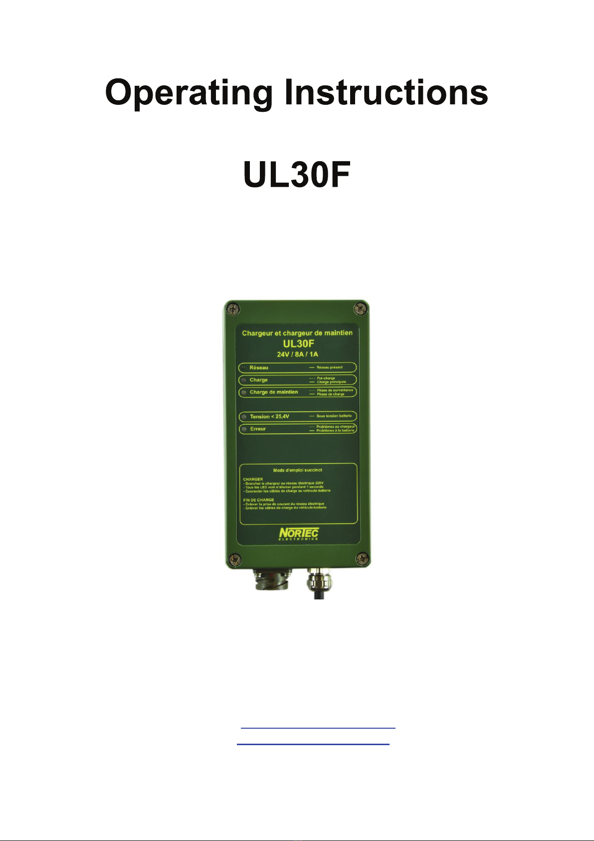
This manual by Nortec Electronics describes the battery charger / trickle charger
UL30 in the UL30F version.
The microprocessor controlled battery charger / trickle charger UL30F for charging
and trickle charging of 24V Lead-Acid-Batteries was designed for the specific request
of the French Army. Military practice recommends capacities from 20Ah to 400Ah for
the UL30F. In case of higher capacities the time of charging will be extend. Civil
batteries can be different to this specification. The manufacturer information must be
defined. The charger in IP65 aluminum housing is protected against shock and
vibrations.
The charging will be connected with the 7-pole VG-connector type 16S. The length of
the charging cable and the ambient temperature will be compensated by the software
of the UL30F. Due to its automated trickle charging program, the battery can be
unlimited connected to the battery charger without being damaged.
Attention
The working- and operating procedures must always be observed to prevent any risk
to the operator and the device.
Note
The technical explanations are intended to provide a better and more convenient
understanding. Please consider the drawn attention to specific operating
requirements and procedures.
In the case of deviations or incompletion, please inform:
NorTec Electronics GmbH & Co. KG
An der Strusbek 32 B
D-22926 Ahrensburg
Tel: +49/ (0) 4102/42002
Fax: +49/ (0) 4102/42840
E-Mail: [email protected]
Web: www.nortec-electronics.de

2
Content
1. Technical Information UL30F............................................................ 3
2. General................................................................................................ 5
3. Installation .......................................................................................... 5
4. Electrical Connection ........................................................................ 6
5. Construction....................................................................................... 7
5.1 Housing ......................................................................................... 7
5.2 Front Foil ....................................................................................... 8
6. Charging ............................................................................................. 9
6.1 Preface........................................................................................... 9
6.2 Battery types and charging characteristics............................. 11
6.3 Temperature Compensation...................................................... 12
7. Fault Indication and Rectification................................................... 13
7.1 Continuous Red Light «VOLTAGE <25.4V» ............................ 13
7.2 Flashing Red Light «Device error» ........................................... 14
7.3 Continuous Red Light «Battery error» ..................................... 15
8. Accessories ...................................................................................... 16
8.1 Transportation frame ................................................................. 16
8.2 Vehicle connection cable 032F ................................................. 17
8.3 Battery connection cable 033E ................................................. 17
9. List of Figures .................................................................................. 18
10. Spare Parts and Accessories........................................................ 18

3
1. Technical Information UL30F
Type: UL30F
Part-No.: UL30F.042 109-0037
NSN: 6130-12-399-1912
Manufacturer: NorTec Electronics GmbH & Co. KG
An der Strusbek 32 B
D-22926 Ahrensburg
Tel.: +49/ (0) 4102 / 42002
Fax: +49/ (0) 4102 / 42840
E-Mail:[email protected]
Web:www.nortec-electronics.de
Mains voltage: 230V ±10% / 50-60 Hz
Input power: <500VA (max.)
Output voltage: max. 35VDC ±1% (Device limited)
Output voltage pre-charging: 28,8VDC ±1% (constant voltage)
Output current main-charging: 8A ±5% (constant current)
Output voltage main-charging: 28,8VDC ±1% (constant voltage)
Output current trickle-charging: 1A ±5% (constant current)
Display: 5 Led’s
EMV: According to VG95 373-GwK 3, EN55022,
EN61000-3-2, EN61000-3-3, EN61000-4-2, -3, -4,
-5, -6, and -11.
Protection class: IP65

4
Operating temperature: -25 to +40 °C (in case of higher temperature
the output power will be reduced)
Storage temperature: -40 to +85 °C
Humidity: (5-95) % for Tu=55°C
Dimensions (L x H x l in mm): 240 x 120 x 90
Weight: 2.3 kg without charging cable
Confirmations: CE Conformity
Mains connection: Protective contact plug with double
protection contact system
Warranty: 24 months

5
2. General
We congratulate you for buying UL30Li
The housing contains two chargers:
•• Battery-charger
•• Trickle-charger
Latest microprocessor technique is responsible for charging your battery according to
UIUa-curve (recommended by the leading battery producers) which guarantees the
maximum lifespan for the battery. Long-term experience in the German Army has
shown that intermitting I-charge is superior to constant voltage trickle-charging.
The vehicle parks of German Army show very convincing results even for vehicles
which are not in use most of the time. A functioning deep discharged battery will be
charged up to the highest possible capacity and kept at this level starting at a
remaining voltage of about 6V. While charging it stays closed and connected to the
vehicle. Batteries with failures will be recognized.
The status of the charging and the device will be indicated by the 5 LEDs of the
device at any time.
3. Installation
A voltage of 230V ±10% / 50-60 Hz is necessary for using this battery charger.
Please check in advance whether this voltage is available and corresponds to the
value on the type label of the charger. The design of the UL30F doesn’t require a
certain order of installation and handling. Especially the wrong polarity protection
prevents installation damages.
We recommend the following procedure:
1. Connect the vehicle to AC mains. Short flashing of the indication LED shows
that the charger finished its Selftest successfully and is ready for use. The
device starts charging automatically.
2. Connect the charging cable correct to the battery. In case the voltage is below
6V please check battery voltage and connection.
3. Disconnect the charger from the power supply first. Then remove the charging
cable from the vehicle

6
Note
Before the charger will be switched on, the battery connection cable hast o be
contacted. Charging cable and battery must be checked for contamination and
mechanical and electrical condition before connection.
•Connect the mains plug, green LED "Mains okay" lights up
•Internal functioning test: all LED´s lights up for about one second
•Afterwards the red LED „Pre-charging Main-charging“ lights up
•In case of a loaded Battery over 25.0V is connected, the charger starts Main-
charging and skip over Pre-charging. If the battery reached the cutoff voltage
of 28.8V and cutoff current of 1A the charger starts Monitoring/Trickle charging
4. Electrical Connection
Provide a contact socket (230V ±10% / 50-60 Hz) in the radius around the planned
installation position of the UL30F
Note
The number of devices in regard to the protection values of the power supply lines
must be limited:
Max. Input power UL30F: 500VA = 2.5A @ 200V AC net voltage (under voltage)

7
5. Construction
5.1 Housing
The UL30F battery charger is built into a dust and spray-water protected aluminum
housing with protection class IP65. All power modules are connected to the rear wall
in a heat-tight manner.
The mains cable is watertight and strain-relieved connected to the housing by a PG
gland. The connection of the charging cable is also located on the underside of the
device.
On the front panel of the housing are five indicator LEDs.
The front foil protects the display elements against moisture and is descried with the
short instruction.
Pic. 1: UL30F

8
5.2 Front Foil
Pic. 2: Front foil UL30F
Legend
MAINS ___ Mains okay
CHARGE ----- Pre-charging
___ Main-charging
TRICKLE CHARGE ----- Monitoring
___ Charging
VOLTAGE <25.4V ___ Battery undervoltage
FAUT ----- Device error
___ Battery error

9
6. Charging
6.1 Preface
Proper battery charging is the first prerequisite for a long battery life. The UL30F
treats any kind of lead-acid-batteries with a nominal voltage of 24V in the optimum
way.
In order to avoid permanent damage on the battery caused by deep discharge, which
can lead the battery being unusable, the battery has to be checked regularly.
Please consider that only charged batteries should be stored. A deep discharge
battery can destroy itself within a few days.
A functioning battery with open-circuit voltage greater than 24V can be easily
charged with up to 8 Amps to its charging voltage of 28.8V. The charging voltage is
preset by the device software.
After the open-circuit voltage has been reached, the charger can be left on the
battery until the charging current falls to 1 Amp given by the software side and the
battery is optimally charged.
If the battery is deep discharged Irreversible chemical processes may occur in the
battery. This may reduce the battery's current-carrying capacity significant.
In this case the pre-charge is used to try to reverse the chemical reaction.
First the charging program checks if the pre-charge is required. In this case the
battery must recover within a predetermined time. Is the pre-charge time exceeded
12h, the device displays fault.
Attention
Disconnect the charger from the power supply first. Then remove the charging cable
from the vehicle.
10
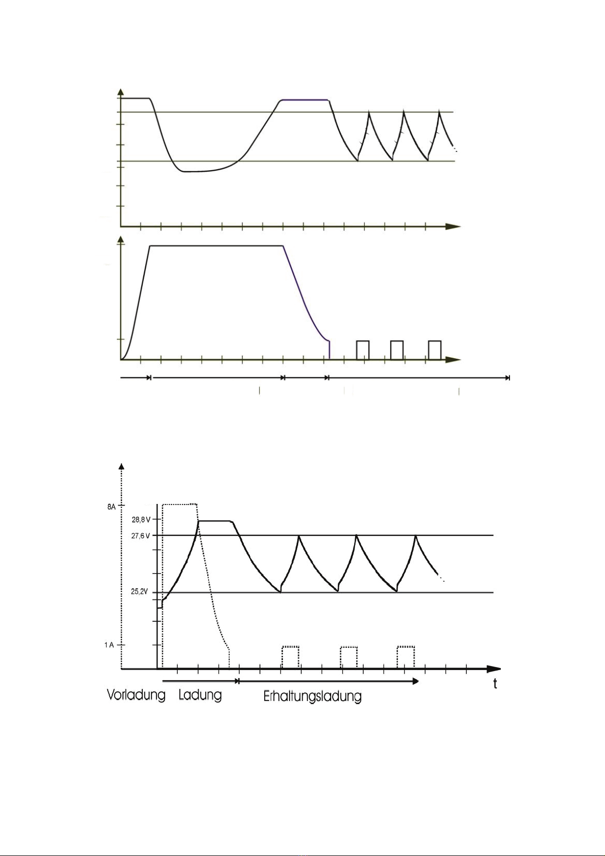
Pic. 3: Current and Tension during charging a deep discharged 24V lead-acid-battery
Pic. 4: Current and Tension during charging a halfway discharged 24V lead-acid-battery
28,8 V
28,6 V
25,4 V
8 A
1 A
Tension
C
urrent
Pre-Charge I-Charge U-Charge Trickle-Charge
Tension
Pre-Charge Charge Trickle-Charge
Current

11
6.2 Battery types and charging characteristics
The battery charger and trickle charger UL30F can be used for 24V lead-acid
batteries. Military practice recommends capacities from 20Ah to 400Ah for the
UL30F. In case of higher capacities the time of charging will be extend. Civil batteries
can be different to this specification. The manufacturer information must be defined.
The integrated charging methods are optimized for 24V serially or parallel connected
lead-battery sets according to VG96 924.
The battery charger and trickle charger UL30F is equipped with an IUa charging
program (UIUa charge for deep-discharge batteries) with the following charging
ranges:
•Charge divided into pre-charge (U), main charge (I) and main charge (U)
•Trickle charging
The long-term experience with the German armed forces shows that the I-trickle-
charging method with upper and lower switching point (saw-tooth-charging-curve) in
this device is clearly superior to the conventional U- or I-U charging method.
Note
The charging functions cannot be chosen separately, because they are part of a
closed function. The charging mode will be selected automatically after connection
the battery:
•After switching on the supply voltage with the already connected battery.
•After a power failure and return of the supply voltage.
•When the lower switching point of 25.2V during trickle-charging e.g. by
connecting a consumer, is exceeded for more than 10 seconds.
12
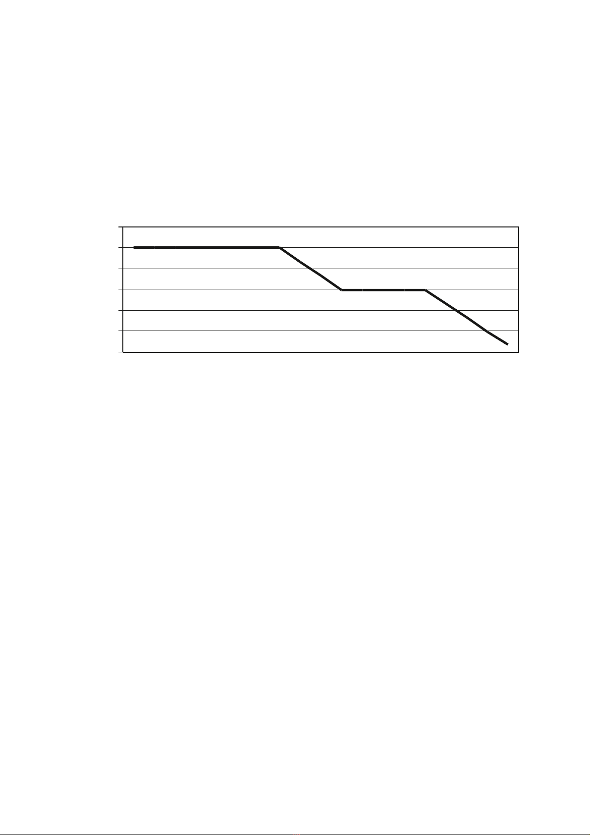
6.3 Temperature Compensation
The UL30F works with a temperature compensation of the charge voltage according
to the specifications of the battery manufacturers. This results in optimal charging
even under extreme climatic conditions and prevents battery damage.
Charging Voltage per cell
2
,
2
5
2
,
3
2
,
3
5
2
,
4
2
,
4
5
2
,
5
2
,
5
5
-
3
5
-
3
0
-
2
5
-
2
0
-
1
5
-
1
0
-
5
0
5
1
0
1
5
2
0
2
5
3
0
3
5
4
0
4
5
5
0
5
5
T
e
m
p
e
r
a
t
u
r
[
°
C
]
L
a
d
e
s
p
a
n
n
u
n
g
[
V
/
Z
e
l
l
e
]
Pic. 5: Temperature compensation
Temperature in
°C

13
7. Fault Indication and Rectification
7.1 Continuous Red Light «VOLTAGE
<
25.4V»
The Red LED lights up when the battery voltage drops below 25.4V. The Red LED
can lights up in conjunction with the LED „Pre-charging “, „Main-charging” or „Trickle
Charging”.
Possible Causes
•a deep discharged battery
•a defect battery e.g. short circuit of a cell
•a connected electrical load which exceed the charging current
Reasons and Measures
- Deep discharged battery?
•Measuring of the battery voltage with a multimeter
•In case of a battery voltage between 2V and 25.4V, continue the charging
process by monitoring the battery voltage. The recharging a deep discharged
battery pack of 100Ah may take up to 24 hours.
- Short circuit of a battery cell?
•Check the battery voltage of every single battery in the set.
•In case of a battery voltage below 0.5V, the complete battery set needs to be
checked.
- Battery connection or charging cable broken?
•Visual check of the charging cable, its pins and the device connector.
•Replace the charging cable and continue charging.
- Short circuit of the charging cable?
•Electrical conductor check of the charging cable and its pins.
•Replace the charging cable and continue charging.
- Battery wrong connected to the device?
•Continue with correct connected battery charger and charging cable.
•Check of none switched off electrical loads to the battery.

14
7.2 Flashing Red Light «Device error»
Reasons and Measures
- Charging cable not connected?
•Check and connect
- Power supply unit fuse 2A defect?
•Replace defective fuse and repeat procedure.
•If the defect still exists the battery charger needs to be checked by repair
department or manufacturer.
- Charging cable defect?
•Connect disconnected battery clamps to the battery
•Check and repair the charging cable
•Replace of the charging cable
- Switching power supply defect?
•Forward the device to the repair department or manufacturer.

15
7.3 Continuous Red Light «Battery error»
Possible Causes
•The battery connection is interrupted.
•The battery is still deep discharged and not able to be charged even after the
permissible time of pre-charging.
•The allowed time of main-charging is exceeded and the charging current is not
decreased to 1A.
•There is a device fault. The device needs to be checked by repair department
or manufacturer.
Reasons and Measures
•Remove the battery pack from the vehicle
•Indicate the faulty battery
•If necessary, assembling of a new battery pack
Note
Only use batteries in a battery set with the date of manufacture is within 12 months
apart.
Use only identical battery types. Never mix gel batteries with batteries containing
liquid electrolyte.
Use only batteries with a capacity difference of max. 20%.
Attention
The weakest battery determines the life of the entire battery pack.

16
8. Accessories
8.1 Transportation frame
Up to two devices UL30F can be fixed on the transportation frame with two main
sockets. The transportation frame has a connection cable of 10m length. Up to 8
devices may be connected to a single mains socket in a row which is fused with 16A.
Pic. 6: Transportation frame

17
8.2 Vehicle connection cable 032F
Vehicle connection cable for direct connection of battery chargers with 7-pole
connector type 16S and vehicle with external start adapter (two-pole according to VG
96 917).
Pic. 7: Vehicle connection cable 032F
8.3 Battery connection cable 033E
The cable enables direct connection of battery chargers with 7-pole connector type
16S and the battery with 80A battery clamps.
Pic. 8: Battery connection cable 033E

18
9. List of Figures
Pic. 1: UL30F S. 7
Pic. 2: Front foil UL30F S. 8
Pic. 3: Current and voltage of a 24V Lead-Acid-Battery S. 10
Pic. 4: Typical voltage progress of a 24V Lead-Acid-Battery S. 10
Pic. 5: Curve temperature compensation S. 12
Pic. 6: Transportation frame S. 16
Pic. 7: Vehicle connection cable 032F S. 17
Pic. 8: Battery connection cable 033E S. 17
10. Spare Parts and Accessories
Spare parts Type Part-No.__________
Battery charger and trickle charger UL30F UL30F.042 109-0037
Manual UL30F 315 570 002 001
Front foil UL30F 108 058 012 003
LED-board UL30i 207 003 243 001
Main-board UL30 207 053 230 001
Net cable (5m) 3G1.0mm² 108 069 000 020
Connector plug 7-pole CA3102E16S-1P UL30 110 010 010 002
Transistor IRFP460 101 010 024 000
Diode STPS80150 101 030 200 000
Magnet foot (pcs.) UL30i 108 205 906 436
Accessories Type Part-No.__________
Transportation frame UL30 EL11.9440 000 269
Net cable for transportation frame (10m) 3G1.5mm² 209 040 003 150
Vehicle connection cable 032F 10m Kabel 309 010 073 005
Battery connection cable 033E 10m Kabel 309 010 072 006
Table of contents
Other nor-tec Batteries Charger manuals


