Norac UC4+ User manual
Generic (Fixed Boom)
Installation Manual
Spray Height Controller
Improving the competitiveness of Industry and
Agriculture through Precision Measurement

Printed in Canada
Copyright ©2005-08 by NORAC Systems International Inc.
Reorder P/N: UC4+BC+GN2-INST Rev D (Generic Fixed Boom)
NOTICE
NORAC Systems International Inc. reserves the right to improve products and their specifications without notice and without the requirement to update
products sold previously. Every effort has been made to ensure the accuracy of the information contained in this manual. The technical information in
this manual was reviewed at the time of approval for publication.

TABLE OF CONTENTS
1INTRODUCTION ..................................................................................................................................................1
2GENERAL SYSTEM DESCRIPTION ..................................................................................................................2
3PARTS LISTS ......................................................................................................................................................3
4INSTALLATION PROCEDURE ...........................................................................................................................5
4.1 WING SENSOR INSTALLATION ........................................................................................................................5
4.2 ELECTRICAL INSTALLATION............................................................................................................................7
4.2.1 Control Panel 7
4.2.2 Inside Cab 8
4.2.3 Outside Cab 9
4.2.4 Electrically Teed Installation 10
4.3 COMPLETING THE INSTALLATION ..................................................................................................................12
5CALIBRATING THE SLANT VALVE ................................................................................................................13
5.1 OVERVIEW...................................................................................................................................................13
5.2 VALVE DEADZONE TEST ..............................................................................................................................14
5.3 VALVE GAIN TEST .......................................................................................................................................15
6ELECTRICAL REFERENCE – CABLE DRAWINGS........................................................................................16
6.1 ITEM C02: 44668 –SENSOR BRANCH CABLE...............................................................................................16
6.2 ITEM C10: 44650-35/39 –POWER CABLE GENERIC .....................................................................................17
6.3 ITEM C11: 44651-03 –EXTENSION CABLE VALVE GENERIC .........................................................................18
6.4 ITEM C12A: 44658-35 –GENERIC INTERFACE CABLE ..................................................................................19
6.5 ITEM C12B: 44658-36 –GENERIC WING INTERFACE CABLE.........................................................................20
6.6 ITEM C14: 44658-28 –INTERFACE CABLE POWER PIGTAIL ..........................................................................21
6.7 ITEM C15: 44658-31 –INTERFACE CABLE HAND CONTROL PIGTAIL .............................................................22
6.8 ITEM C17: 44658-42 –GENERIC INTERFACE ROLL CABLE ...........................................................................23

1
1 INTRODUCTION
Congratulations on your purchase of the NORAC UC4+ Spray Height Controller. This system is
manufactured with top quality components and is engineered using the latest technology to provide
operating features and reliability unmatched for years to come.
When properly used the system can provide protection from sprayer boom damage, improve sprayer
efficiency, and ensure chemicals are applied correctly.
Please take the time to read this manual completely before attempting to install the system. A thorough
understanding of this manual will ensure that you receive the maximum benefit from the system.
YOUR INPUT CAN HELP MAKE US BETTER! If you find issues or have suggestions regarding
the parts list or the installation procedure, please don’t hesitate to contact us via the information
given below:
Phone: 1 800 667 3921 Canada (Toll Free)
1 866 306 6722 United States (Toll Free)
(+33) 06 03 87 80 78 Europe
(+1) 306 664 6711 All other regions
Web: www.norac.ca
2
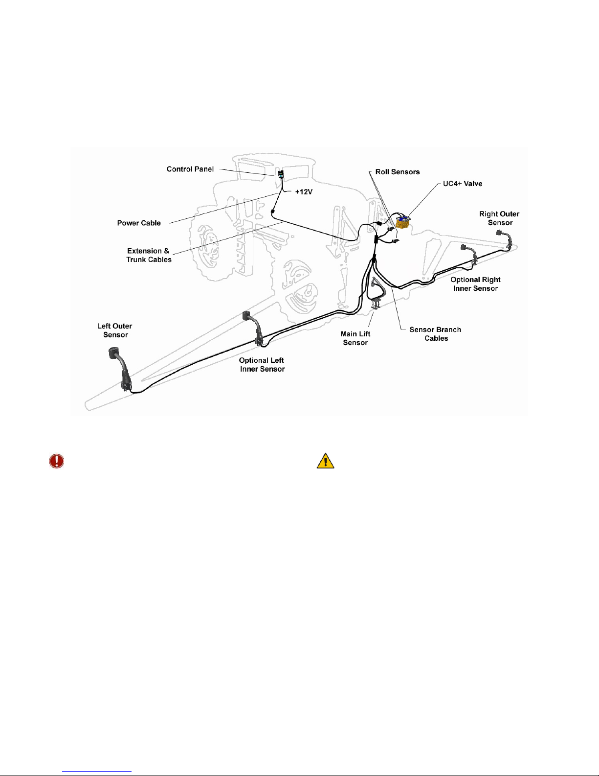
2 GENERAL SYSTEM DESCRIPTION
Figure 1 depicts the general system layout of the UC4+ Spray Height Control system.
Figure 1 – System Components and General Location
NOTICE:
Every effort has been made to ensure the
accuracy of the information contained in this
manual. All parts supplied are selected specially
to fit the sprayer to facilitate a complete
installation. However, NORAC cannot
guarantee all parts fit as intended due to the
variations of the sprayer by the manufacturer.
Please read this manual in its entirety before
attempting installation.
ATTENTION:
When installing the UC4+ Spray Height Control
system please be aware that at a point in the
installation your sprayer booms will be
inoperative until the installation is complete.
Any installation procedure requiring boom
movement will need to be done first. Once the
hydraulics have been disconnected you must
complete the electrical installation before the
booms become operative.
Other manuals for UC4+
41
Table of contents


