NorAM 65ET T4 FINAL User manual
-1
1
7),1$/
65
E7
|
Motor Grader
Operator’s Manual
2FWREHU, 201
Part # ϯϰϰϵϭ
S/N: Tier ϰ&ŝŶĂů65ETϭϬϭϬϭͲ hW

This page intentionally left blank.

NORAM 65ET GRADER
Table of Contents 1
NORAM 65ET GRADER
TABLE OF CONTENTS
SAFETY
Safety Messages ....................................1-1
Safety Symbol Explanation .................. 1-2
Safety Decal Locations ......................... 1-6
GENERAL INFORMATION
Intended Use ......................................... 2-1
Introduction to this Manual ................. 2-1
Orientation ............................................ 2-2
Machine Description .............................2-2
Identification Numbers ........................ 2-3
Component Identification and
Locations .......................................... 2-5
Electronic Display ............................... 2-28
OPERATION
Mounting and Dismounting ................. 3-1
Daily Pre-Starting Inspection .............. 3-1
Rollover Protective Structure (ROPS) .3-3
Driving the Machine .......................... 3-8
Moldboard and Implement Operation 3-11
LUBRICATION AND MAINTENANCE -
GRADER COMPONENTS
Safety Messages ....................................4-1
General Information ............................. 4-4
Accessing Lubrication and
Check Points ....................................4-6
Maintenance Intervals ....................... 4-10
Every 10 Hours or Daily ..................... 4-12
Every 50 Hours or Weekly ................. 4-17
Every 100 Hours ................................. 4-21
Every 250 Hours or Monthly .............. 4-23
Every 500 Hours or 3 Months ............ 4-26
Every 500 Hours or 6 Months ............ 4-30
Every 1000 Hours or 6 Months .......... 4-33
Every 2000 Hours or 1 Year ............... 4-36
When Required ................................... 4-40
LUBRICATION AND MAINTENANCE -
CUMMINS TIER 4 FINAL
General Information ............................. 5-1
Maintenance Intervals ......................... 5-3
Every 10 Hours or Daily ....................... 5-4
Every 250 Hours or Every 3 Months ... 5-7
Every 500 Hours or Every 6 Months ... 5-8
Every 1000 Hours or 1 Year ............... 5-11
Every 2000 Hours or 2 Years ............. 5-12
When Required ................................... 5-13
LUBRICATION AND MAINTENANCE -
CAT TIER 4 FINAL
General Information ............................. 6-1
Maintenance Intervals ......................... 6-3
Every 10 Hours or Daily ....................... 6-4
Every 50 Hours or Weekly ................... 6-7
Every 250 Hours ................................... 6-9
Every 500 Hours ................................... 6-9
Every 500 Hours or 1 Year ................. 6-10
Every 1000 Hours ............................... 6-18
Every 1500 Hours ............................... 6-18
Every 2000 Hours ............................... 6-19
When Required ................................... 6-20

NORAM 65ET GRADER
2 Table of Contents NORAM 65ET GRADER
SPECIFICATIONS
Options .................................................7-15
TROUBLESHOOTING
Engine ....................................................8-1
Transmission .........................................8-1
Hydraulics and Implements .................8-2

NORAM 65ET GRADER
1-1
Safety 1
Safety Messages
SECTION 1: SAFETY
SAFETY MESSAGES
General safety messages appear in this Safety Messages section. Specific safety messages are located
in appropriate sections of the manual where a potential hazard may occur if the instructions or
procedures are not followed.
Personal Safety
A signal word “DANGER”, “WARNING”, or “CAUTION” is used with the safety alert symbol.
Safety signs with signal word “DANGER”, “WARNING”, or “CAUTION” are located near specific
hazards.
DANGER Indicates a hazardous situation that, if not avoided, will result in death or serious
injury.
WARNING Indicates a hazardous situation that, if not avoided, could result in death or serious
injury.
CAUTION Indicates a hazardous situation that, if not avoided, could result in minor or
moderate injury.
Machine Safety
NOTICE: The word “NOTICE” is used to inform the reader of something that needs to be known to
prevent machine damage and/or property damage if a certain procedure is not followed.

1
NORAM 65ET GRADER
1-2
Safety
1
Safety Symbol Explanation
SAFETY SYMBOL EXPLANATION
This is the safety alert symbol. This symbol is used in combination with an exclamation
mark or other symbols to alert you to the potential for bodily injury or death.
Read Operator’s Manual and safety signs before operating machine.
Check machine before operating. Machine must be in good operating condition
and all safety equipment installed and functioning properly.
Wear personal protective equipment as required by the job. Dress properly.
Wear close fitting clothing and confine long hair. Avoid wearing jewelry such as
rings, wrist watches, necklaces or bracelets. Consult your employer, site
supervisor or OSHA for specific requirements for:
• a hard hat
• safety glasses
• work shoes or boots
• reflective clothing
• hearing protection
• gloves, as needed
Keep spectators away.

NORAM 65ET GRADER
1-3
Safety 1
Safety Symbol Explanation
Refer to and follow the Shutdown Procedure before servicing, cleaning,
repairing, or transporting machine.
Pressurized fluid can penetrate body tissue and result in serious injury or death.
Leaks can be invisible. Keep away from any suspected leak. Relieve pressure in
the hydraulic system before searching for leaks, disconnecting hoses, or
performing any other work on the system. If you must pressurize the system to
find a suspected leak, use an object such as a piece of wood or cardboard rather
than your hands. When loosening a fitting where some residual pressure may
exist, slowly loosen the fitting until oil begins to leak. Wait for leaking to stop
before disconnecting the fitting. Fluid injected under the skin must be removed
immediately by a surgeon familiar with this type of injury.
Contact with moving parts can cause death or serious injury.
• Keep hands, feet, and clothing away from power-driven parts.
• Wear close-fitting clothing and confine long hair. Avoid wearing jewelry,
such as rings, wristwatches, necklaces, or bracelets.
• Keep all shields and guards in place and properly secured.
Explosion and separation of a tire can cause serious injury or death.
• Never stand beside the tire when inflating.
• Never inflate beyond the tire manufacturer’s recommended tire pres-
sure.
• Always mount, demount or inflate tires with properly trained and quali-
fied personal.
Diesel Exhaust Fluid (DEF) may cause eye irritation and can be moderately
irritating to the skin. Exposure to decomposition products may cause a health
hazard. Serious effects may be delayed following exposure.
DEF is not expected to produce significant adverse health effects when the
recommended instructions for use are followed.
• DO NOT breathe DEF vapor or mist.
• DO NOT eat, drink, or smoke when using DEF.
• Avoid DEF contact with eyes, skin, and clothing.
• Wash thoroughly after handling DEF.

1
NORAM 65ET GRADER
1-4
Safety
1
Safety Symbol Explanation
General Safety Messages
• Only responsible persons, delegated to do so, should operate any machine.
• Be sure safety shields, guards, and barriers are in place and in good condition before starting
the machine.
• Check to see that all personnel are clear of the machine before starting.
• Place all controls in NEUTRAL or OFF position when shutting the machine down. Apply the
park brake. Be sure all controls are in NEUTRAL or OFF position and the park brake is applied
before starting the engine.
• When parking the machine for the night, provide the appropriate lighting and marking if the
machine is adjacent to a roadway or a construction area where work is in progress.
• DO NOT leave the machine unattended when the engine is running.
• Keep the machine clean. The process of cleaning will reveal loose bolts, hydraulic lines, fittings
and other trouble spots.
• Always keep the operator’s platform clean and free from grease, oil, rags, and loose tools to help
prevent slipping and falling.
• Before cleaning, adjusting or servicing the machine, shut engine down and place all controls and
switches in neutral or off position. Completely lower all attachments, or securely support raised
components. A variation of the above procedure may be used if instructed within this manual.
• Refuel the machine only with the engine OFF. Never smoke or have an open flame in area when
refueling.
• Refill or check the radiator only when the engine is OFF and the radiator is not hot. Turn cap
slowly to the first stop to relieve the pressure before removing the cap.
• Before starting or continuing operation, correct or report any mechanical deficiency that may
cause further damage.
• Securely support with suitable blocking the mainframe, moldboard or other components that
are suspended or held aloft by slings, hoists, jacks or hydraulic cylinders before working under
or between them.
• Make no modifications to your equipment unless specifically requested by NorAm.
• No riders allowed on machine. Only a seated operator, with seat belt securely fastened, is per-
mitted on the machine during grading operation or when roading between job sites. Operator’s
platform is for properly trained and qualified personnel only.
The following general safety rules are important for safe operation of the
machine.

NORAM 65ET GRADER
1-5
Safety 1
Safety Symbol Explanation
Slope Operation Safety
Drive the machine at a speed suitable for the terrain. Avoid sudden stopping, starting or turning.
Avoid traveling across slopes. Drive up and down slopes when possible. Safe operating slope depends
upon many factors, including:
• Keep moldboard low and close to the ground. Lower moldboard to ground if machine starts to
slip.
• Select the same gear when going downhill as would be used going uphill. Select the gear before
starting down slope. DO NOT freewheel down slopes or hills.
• Uphill or downhill position of moldboard
• Uneven, rough or slippery ground conditions
• Potential for ground giving way, causing either unplanned forward, reverse, or sideways tilt
• Nearness of ditches, ruts, stumps, or other obstructions and sudden changes in slope
• Travel speed and turning rate
• Front axle only steering versus frame articulation and front axle steering
• Braking performance
• Skill of operator
Safety Decals - Inspect
Safety decals located on your machine contain important and useful information that will help you
operate your equipment safely. To assure that all decals remain in place and in good condition, follow
the instructions given below:
• Keep decals clean. Use soap and water, not mineral spirits, abrasive cleaners, or other similar
cleaners that will damage the decal.
• Replace any damaged or missing decals. When attaching decals, the temperature of the mount-
ing surface must be at least 40°F (5°C). The mounting surface must also be clean and dry.
• When replacing a machine component with a decal attached, replace the decal also.
• Replacement decals can be purchased from your NorAm dealer.
Check Laws And Regulations
Know and obey all federal, state, and local laws and regulations that apply to your work situation.
Fire Extinguisher
Fire extinguisher (not supplied with machine) should be mounted on the machine for easy access to
the operator.
Failure to follow any of the preceding safety instructions or those that follow
within this manual, could result in serious injury or death. This machine is to be
used only for those purposes for which it was intended as explained in this
operator’s manual.

1
NORAM 65ET GRADER
1-6
Safety
1
Safety Decal Locations
SAFETY DECAL LOCATIONS

NORAM 65ET GRADER
2-1
General Information 2
Intended Use
SECTION 2: GENERAL INFORMATION
INTENDED USE
The 65ET motor grader is intended for construction and maintenance of dirt and gravel roads, site
preparation for paved roads and buildings, and maintenance of road shoulders and ditches.
Always use the machine in accordance with the instructions contained in this Operation and
Maintenance Manual, safety signs on the machine, and other material provided by NorAm.
Proper maintenance and repair is essential for safety, and for efficient operation of the machine. DO
NOT use the machine if it is not in suitable operating condition.
INTRODUCTION TO THIS MANUAL
This manual provides correct procedures for break-in, driving, operating and maintaining your
machine.
Read this manual carefully and keep it tethered to the manual holder on the machine for future
reference. If at any time a question arises concerning the equipment, contact an authorized NorAm
dealer. Factory trained personnel, genuine replacement parts and the necessary equipment are
available for all service requirements.
This machine has been designed and built to give outstanding performance and ease of operation
under a variety of operating conditions. To maintain your machine and ensure trouble free operation,
the routine maintenance as specified in this manual must be carried out at the recommended
intervals. Prior to delivery, the machine was carefully inspected at the factory and by your dealer.
All information in this manual is based on the latest information available at the time of publication.
Dimensions and weight are approximate and the illustrations may not show the equipment in
standard configuration. Your machine may have product improvements and features not yet
contained in this manual.
NorAm reserves the right to make changes at any time without notice or obligation.

1
NORAM 65ET GRADER
2-2
General Information
2
Orientation
ORIENTATION
References are made throughout this manual to describe
location and direction. Unless otherwise specified,
reference to direction is from the operator's seat.
MACHINE DESCRIPTION
The grader is a construction machine with a long moldboard blade used to create a flat surface during
the grading process. The grader has a front and rear axle, with the engine and operator station
located on the rear module.
The grader is articulated between the front and rear axles. Articulation allows the grader to bend at a
pivot point between the front and rear modules. Steering is achieved through the front tires, together
with front tire lean, and frame articulation.
The moldboard is attached to the turn circle suspended from the front frame by an “A” frame drawbar
positioned by a series of hydraulic cylinders.
Power from a Caterpillar C3.4B Tier 4 Final or Cummins QSF3.8 Tier 4 Final engine is delivered
through a full power shift transmission, with torque converter, to the rear axle, equipped with a
torque proportioning rear differential, and through tandem cases to the rear wheels.
An optional dozer blade, ripper and scarifier implements and cab, with heater and optional air
conditioning are available. The cab is ROPS and FOPS certified.

NORAM 65ET GRADER
2-3
General Information 2
Identification Numbers
IDENTIFICATION NUMBERS
The motor grader and major components are identified by serial numbers. The serial numbers are
required when ordering parts. For easy reference the identification data should be recorded and kept
in a safe place away from the machine.
The vehicle serial number and point of manufacture is
stamped into the serial tag (1) placed on the left side of
the steering column.
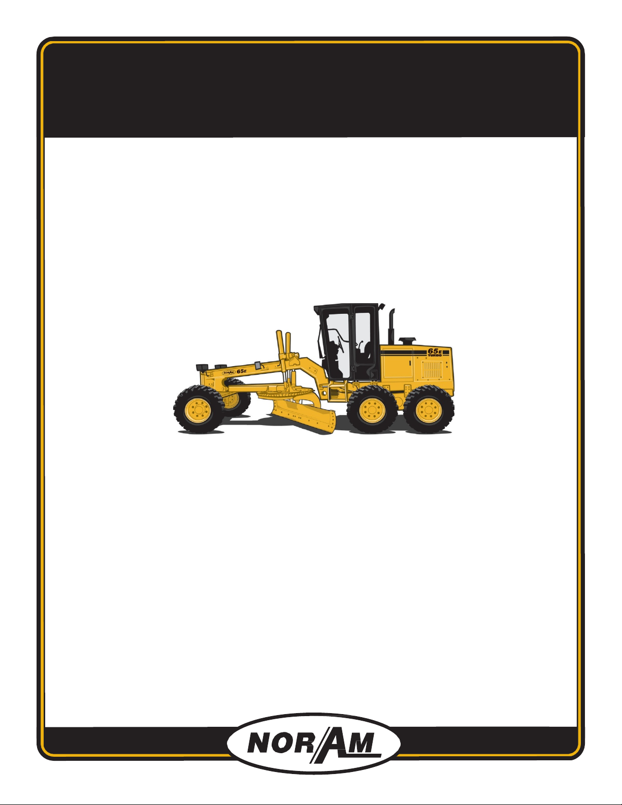
The vehicle serial number (1) is also stamped into to
right side of the frame below the operators platform.
An engine identification plate (1) is located on the top of the Cummins engine and on the left side of
the Cat engine.
CUMMINS T4 FINAL ENGINE CAT T4 FINAL ENGINE
1
1
1
1
1
NORAM 65ET GRADER
2-4
General Information
2
Identification Numbers
The differential identification plate (1) is located on the
right tandem support.
The transmission identification plate (1) is located on the
front side of the transmission below the drive shaft.
1
1
NORAM 65ET GRADER
2-5
General Information 2
Component Identification and Locations
COMPONENT IDENTIFICATION AND LOCATIONS
Protective Shield
The engine and transmission are enclosed to protect personnel from hot and moving parts. An
additional guard encloses the cooling fan.
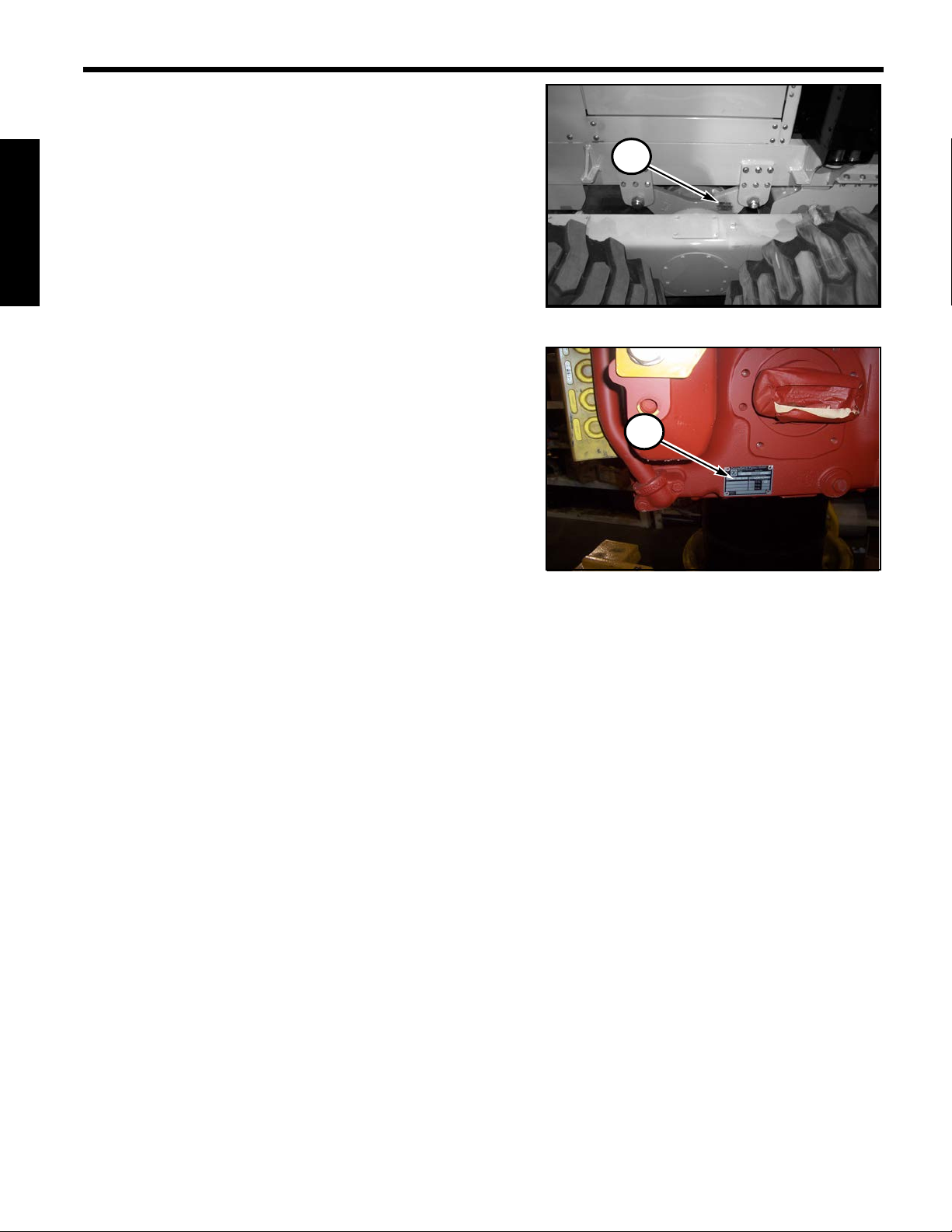
Engine access doors are located on each side of the engine
cover. A lock is in the handle (1). Turn the handle
clockwise 180° to unlatch and counter-clockwise 180° to
latch.
DO NOT operate machine until thoroughly familiar with the location and operation
of all controls.
DO NOT operate motor grader with engine enclosure removed or access doors
open and unlatched. DO NOT operate with fan guard removed or broken.
1

1
NORAM 65ET GRADER
2-6
General Information
2
Component Identification and Locations
When equipped with the Cummins QSF3.8 Tier 4 Final engine, opening the left side engine
compartment door provides access to the following:
1Electronic Control Module (ECM) 6Fuel Pump
2Crankcase Breather 7Oil Fill
3Water Pump 8Water Separator
4Oil Filter 9Fuel Primer
5Fuel Filter 10 Air Cleaner
3
2
4
1
8
7
6
5
Cummins QSF3.8 Tier 4 Final
10
9

NORAM 65ET GRADER
2-7
General Information 2
Component Identification and Locations
When equipped with the Cummins QSF3.8 Tier 4 Final engine, opening the right side engine
compartment door provides access to the following:
1Air Filter Indicator 10 SCR System
2Hydraulic Tank Filter 11 Heater Core Shutoff Valve
3Hydraulic Tank Fill 12 Heater Control Circuit Breaker
4Hydraulic Tank Sight Gauge 13 Stud Fuse
5A/C Dryer 14 Main Power Circuit Breaker
6Master Switch 15 Alternator
7Engine Diagnostic Port 16 Washer Fluid Tank
8Fuse Panel 17 Starter
9Turbocharger 18 A/C Condenser
Cummins QSF3.8 Tier 4 Final
110
2
34
6
578
9
11
13
14
15
16
17 18
12

1
NORAM 65ET GRADER
2-8
General Information
2
Component Identification and Locations
When equipped with the CAT C3.4B Tier 4 Final engine, opening the left side engine compartment
door provides access to the following:
1Engine Electronic Control Module (ECM) 8Fuel Primer
2Glow Plug Control Unit (GPCU) 9Water Separator
3Diesel Exhaust Fluid (DEF) Injector 10 Fuel Filter
4Selective Catalytic Reduction (SCR) 11 Engine Oil Filter
5A/C Compressor 12 Engine Oil Fill
6A/C Dryer 13 Hydraulic Tank Access Cover
7Heater Core Shutoff Valve 14 Air Cleaner
2
5
1
3
CAT C3.4B Tier 4 Final
10
9
13
8
12
11
4
6
7
14

NORAM 65ET GRADER
2-9
General Information 2
Component Identification and Locations
When equipped with the CAT C3.4B Tier 4 Final engine, opening the right side engine
compartment door provides access to the following:
1Hydraulic Tank Filter 10 NOx Sensors
2Hydraulic Filter Gauge 11 Ammonia Sensor (on back of panel)
3Hydraulic Tank Fill 12 Air Filter Indicator
4Hydraulic Tank Sight Gauge 13 Heater Control Circuit Breaker
5Master Switch 14 Main Power Circuit Breaker
6Wait To Disconnect Lamp 15 Alternator
7Engine Diagnostic Port 16 Washer Fluid Tank
8Fuse Panel 17 Engine Oil Dipstick
9Turbocharger 18 Starter
1
CAT C3.4B Tier 4 Final
10
2
34
6
5
78
9
11
12
13
14
15
16
18
17

1
NORAM 65ET GRADER
2-10
General Information
2
Component Identification and Locations
The radiator access door (1) is located on top of the engine cover. The hydraulic reservoir fill cap (2)
and transmission oil fill and dipstick (3) are located behind the right side engine access door.
The fuel fill neck (4) and DEF fill neck (5) are located
behind the left side access door.
FOPS and ROPS
All motor graders are equipped with a Roll Over Protection System (ROPS), Falling Object Protection
System (FOPS) and a seat belt.
Optional for the 65ET is an enclosed cab with heater and optional air conditioning. The cab is also
FOPS and ROPS certified.
1
2
3
54
Table of contents
Other NorAM Construction Equipment manuals


