Noraxon myoMOTION 682 User manual

Nora
x
P-682
8
x
on U.S.A., I
n
8
Rev A (Oct 201
M
n
c.
4)
M
yo
M
M
OT
I
I
ON
Dat
a
User
M
myoMOTIO
a
Lo
g
Man
u
M
odel 6
8
N Data Logg
e
g
ge
r
u
al
82
e
r
r

Noraxon U.S.A., Inc. myoMOTION Data Logger
P-6828 Rev A (Oct 2014)
i
For questions, concerns or additional assistance please contact Noraxon or its Authorized
Representative as specified below.
MManufacturer:
Noraxon U.S.A. Inc.
15770 North Greenway-Hayden Loop, Suite 100
Scottsdale, AZ 85260
Tel: (480) 443-3413
Fax: (480) 443-4327
Email: [email protected]
Web Site: www.noraxon.com
PAuthorized European Representative:
Advena Ltd.
Pure Offices,
Plato Close, Warwick CV34 6WE, UK
Telephone +44(0)1926 800153
+44(0) 845 094 3307
Email: [email protected]
Website: http://www.advenamedical.com
Skype: advenamedical
© Copyright, 2014, Noraxon U.S.A. Inc.
No part of this document may be copied, photographed, reproduced, translated, or reduced to any electronic medium or
machine-readable form without the prior written consent of Noraxon U.S.A. Inc.
Noraxon is a registered trademark of Noraxon U.S.A. Inc. All rights reserved. All other company and product names
contained herein may be trademarks or registered trademarks of their respective companies and are sole property of their
respected owners.

Noraxon U.S.A., Inc. myoMOTION Data Logger
P-6828 Rev A (Oct 2014)
ii
Table of Contents
Section1:Introduction
Brief Description ...................................................................................................... 1
Intended Use .......................................................................................................... 1
Contraindications...................................................................................................... 1
Section2:Definitions
Graphic Symbols and Meanings............................................................................... 2
Glossary of Terms ................................................................................................... 3
Section3:Identification
Model Designation ................................................................................................... 4
Product Versions and Configurations ...................................................................... 4
Section4:GeneralWarningsandCautions
Risks and Benefits.................................................................................................... 5
Safety Information Summary ................................................................................... 5
Section5:GettingStarted
Quick Start Guide .................................................................................................... 6
myoMOTION Quick Start Tutorial-Addendum ......................................................... 8
Section6:PreparingtheProductforUse(SetupInstructions)
Unpacking and Component Identification ................................................................10
Component Inputs, Outputs and Indicators..............................................................11
Component Interconnections ...................................................................................12
Device Communication (Driver) Software Installation .............................................13
Companion Software Installation .............................................................................13
Software Configuration ............................................................................................13
Section7:Pre‐useCheck‐out
Normal Appearance of Signals.................................................................................14
Attaching to Patient or Subject.................................................................................14
Calibration.................................................................................................................14
Section8:OperatingInstructions
Safety Information Summary....................................................................................15
Normal Functions with Interface in PC.....................................................................15
Secondary Functions without PC Interface..............................................................15
Exceptional Functions/Situations (error messages).................................................16
Shutdown after Use..................................................................................................16
Storage and Protecting Between Usages ................................................................17
Section9:AccessoriesandOptionalModules
Accessories ..............................................................................................................18
Section10:Cleaning
Safety Precautions When Cleaning..........................................................................19
Cleaning by Users....................................................................................................19
Section11:Maintenance
Safety Precautions When Performing Maintenance.................................................20
Maintenance by Users..............................................................................................20
Maintenance by Qualified Individuals.......................................................................20
Section12:Trouble‐shooting,FaultDiagnosis
Troubleshooting Chart..............................................................................................22
Website Link to FAQ.................................................................................................22
Radio Considerations...............................................................................................23
Setting the Sensor RF Channels..............................................................................23

Noraxon U.S.A., Inc. myoMOTION Data Logger
P-6828 Rev A (Oct 2014)
iii
Section13:ServiceandRepair
Availability of Circuit Diagrams and Component Lists .............................................24
Submitting Service Requests ...................................................................................24
Returning Equipment................................................................................................24
Section14:ListofSparePartsandConsumables
Consumable Items (electrodes and sensor elements).............................................25
Replaceable Items (fuses, batteries, lead sets) ......................................................25
Section15:TakingProductOutofOperation
Disposal of Equipment and Batteries.......................................................................26
Section16:SpecificationsoftheProduct
Expected Useful Lifetime..........................................................................................27
Dimensions and Weight ...........................................................................................27
Performance Characteristics ...................................................................................27
Energy Consumption, Condition of Use ..................................................................27
Environmental Conditions for Storage and Transport .............................................27
IP (Ingress Protection) Rating..................................................................................27
Section17:TechnicalInformation
Block Diagram .........................................................................................................28
Theory of Operation .................................................................................................28
Electro-Magnetic Compatibility (EMC Tables) .........................................................28
Section18:Appendices
Appendix A—Interference Between WiFi & Sensor Radio Frequency Channels....31
Appendix B—Sensor RF Channel Frequencies.......................................................32
Appendix C—Radiation Exposure Information Regarding Use of DTS Sensors.....33
Appendix D—Radio Regulatory Statements ...........................................................34

Noraxon U.S.A, Inc. MyoMOTION System
P-6828 Rev A (Oct 2014)
1
Section 1: Introduction
BriefDescription
Noraxon’s myoMOTION™ System is a combination of hardware and software that enables the
capture of human motion in three degrees of freedom (3 DOF). A compact Inertial Measurement
Unit (IMU) placed on any segment of the body precisely tracks the 3D angular orientation of that
body section. By positioning individual IMU sensors on two contiguous body segments, the
intervening joint Range of Motion (ROM) can be determined. This concept is easily expandable
from a single joint of interest to a simultaneous 16 sensor full body measurement across all major
articulations.
The myoMOTION sensors transmit the motion of the human body directly to the myoMOTION
receiver or data logger to quantify the angular changes of the selected body segments. The
captured data may then be analyzed using Noraxon software.
The main advantage of this technology is it is easy and quick to use, fully portable and can be
used with independent external cameras. This unique concept gives the user flexibility to operate
the myoMOTION system without limitations.
The myoMOTION data logger brings even more portability to the system. With the myoMOTION
data logger, users can apply the sensors and, using the data logger, record data anywhere during
any activity. This recorded data can then be imported from the data logger into the software for
processing and analysis.
IntendedUse
Noraxon’s 3-D myoMOTION system is intended to measure and quantify angular changes of
selected body segments. The data logger is used to make the system truly portable by offering an
option for recording data without the use of a myoMOTION receiver or a computer. Recorded
data can then be imported into the software for data analysis and reporting.
Intended Users
Researchers and individuals trained in physical medicine, physical therapy or ergonomics
Subject Populations – Medical
Individuals with cerebral palsy, physical injuries, post-surgical or post stroke conditions
Subject Populations – Non medical
Athletes, workers at their worksite, subjects in new product trials
Common Applications
Movement Technique analysis, gait analysis; tracking over time the outcome of surgical,
therapeutic or orthotic interventions; identification of ergonomic stress factors in the workplace or
new product designs; sports performance analysis, and postural assessment.
Contraindications
Use of the myoMOTION analysis system and data logger is contra-indicated in individuals who
have implanted pacemakers.

Nora
x
P-682
8
Se
c
Gra
p
The f
o
enclo
x
on U.S.A., I
n
8
Rev A (Oct 201
c
tion 2:
p
hicSymb
o
o
llowing inter
s
ures and in
t
n
c.
4)
Definit
o
lsandMe
a
national icon
s
t
his user ma
n
A
c
e
T
A
T
R
a
I
d
I
d
A
ions
a
ning
s
and symbol
n
ual. Their m
e
A
pprovalto
m
e
rtifiedbyN
o
T
hedevicege
n
A
5VoltDCp
o
T
heUSBcabl
e
R
eadmaterial
ppears.
d
entifiesthe
m
d
entifiesthe
s
A
dditionalinf
o
s are found
o
e
aning is des
m
arketthispr
o
o
tifiedBody
#
n
eratesradi
o
o
wersourcei
s
e
isappliedt
o
intheInstru
m
anufacture
s
erialnumbe
o
rmationava
o
n the myoM
O
cribed below
.
o
ductinthe
E
#
0473AMTA
C
o
frequencye
sappliedto
t
o
thisconnec
t
ctionManua
l
rofthedevi
c
rofthedevi
c
ilableinase
p
myoMOTIO
O
TION Data
L
.
E
uropeanCo
m
C
oftheUK.
nergyduring
t
hisconnecti
o
t
ion.
lwherevert
h
c
e.
c
e.
p
aratedocu
m
N Data Logg
e
L
ogger
m
munitywa
s
operation.
o
n.
h
issymbol
m
ent
e
r
2
s

Noraxon U.S.A., Inc. myoMOTION Data Logger
P-6828 Rev A (Oct 2014)
3
GlossaryofTerms
myoMOTION Sensor -- A small individual radio transmitter typically worn on the body used to
measure and transmit motion related signals. The myoMOTION System can accommodate up to
8 body worn myoMOTION Sensors on one receiver, or can be configured with two receivers for
up to 16 sensors.
myoMOTION Serial Number – A unique four-character tag used to identify each myoMOTION
Sensor. The members of any myoMOTION network are determined by their serial numbers.
RF – (Abbreviation for Radio Frequency) Wireless communication takes place on assigned radio
frequencies or channels. For the myoMOTION System, RF transmissions occur at frequencies
between 2.4 GHz and 2.5 GHz. Other wireless systems including WiFi and Bluetooth commonly
operate at the same frequencies and can be a source of interference.
RF Channel – RF transmissions for the myoMOTION System can be selected to occur on one of
24 different radio frequencies. The ability to operate over several different frequencies allows the
myoMOTION System to reposition its radio operation if needed to avoid interference.
RF Traffic – The presence of radioactivity present on a given frequency similar to the number of
cars on an expressway. Several users (wireless devices) may be communicating using the same
frequency. Best operation of the myoMOTION System occurs when the RF Traffic is low (no
other users) on the selected RF Channel.
Serial Number – A unique four-character tag used to identify the myoMOTION Data Logger.

Nora
x
P-682
8
Se
c
Mo
d
The
m
Mod
e
Pro
d
The
m
2 DT
S
Mod
e
Mod
e
Mod
e
A
s th
e
equip
Mod
e
Mod
e
x
on U.S.A., I
n
8
Rev A (Oct 201
c
tion 3:
d
elDesign
a
m
odel 682 M
y
e
l 682 myoM
O
d
uctVersi
o
m
odel 682 m
y
S
Footswitch
e
l 500 DTS F
o
e
l 610 Resea
r
e
l 616 Clinical
e
myoMOTI
O
ment is offer
e
e
l 460 – myo
M
e
l 463 – myo
M
n
c.
4)
Identif
i
a
tion
y
oMOTION S
y
O
TION Data
L
o
nsandCo
n
y
oMOTION D
a
sensors.
o
otswitch
r
ch myoMOTI
myoMOTIO
N
O
N System re
q
e
d in combin
a
M
OTION Clini
M
OTION Res
e
i
cation
y
stem Data
L
L
ogger
n
figuratio
n
a
ta Logger c
a
ON Sensor
N
Sensor
q
uires softw
a
a
tion with the
cal Software
e
arch Softwa
L
ogger consis
n
s
a
n accommo
d
a
re to import t
following co
m
re
st
s of:
d
ate up to 16
he data to fo
r
m
puter progr
a
myoMOTIO
myoMOTIO
N
r
analysis, th
e
a
m packages
N Data Logg
e
N
Sensors an
e
myoMOTIO
:
e
r
4
d
O
N

Noraxon U.S.A., Inc. myoMOTION Data Logger
P-6828 Rev A (Oct 2014)
5
Section 4: General Warnings and Cautions
RisksandBenefits
There is no identified risk of physical harm or injury with use of the myoMOTION Data Logger
product. The benefit provided by use of the device is the provision of objective measures to
assess the severity of pathological human movement conditions and gauge any subsequent
improvement offered by therapy, training, prosthetic alterations or ergonomic design changes.
SafetyInformationSummary
Cautions
Never use the myoMOTION System on a person with an implanted pacemaker
Never operate the myoMOTION System within 1 meter of any critical medical device
Never use the myoMOTION System in the presence of flammable anesthetizing agents
or substances.
Never use the myoMOTION System in the presence of strong magnetic fields such as
occurs in the vicinity of MRI (magnetic resonance imaging) equipment.
Never use the myoMOTION System in the presence of heavy electrical machinery such
as close proximity to large motors, elevators, compressors, etc.
Warnings
Do not immerse the myoMOTION Data Logger in any water or liquid
Do not use the myoMOTION equipment on individuals undergoing MRI, Electro Surgery
or Defibrillation
The myoMOTION Data Logger produces results that are informative, not diagnostic.
Qualified individuals must interpret the results
Attention
The operator must be familiar with typical characteristics of the signals acquired by the
myoMOTION equipment and be able to detect anomalies that could interfere with proper
interpretation.

Noraxon U.S.A., Inc. myoMOTION Data Logger
P-6828 Rev A (Oct 2014)
6
Section 5: Getting Started
QuickStartGuide
To begin using the Data Logger, the user must charge the device using the USB A to mini-B
cable provided with the data logger. Once charged, it is necessary to setup the sensors, time and
date before a measurement can be taken.
Note: It is important to press the Save button after each step to ensure the data logger stores
the changes and it will work properly.
For the initial setup: turn the Data Logger on and Press OK to enter the Setup screen.
1. Setup Sensors
Assign Sensors
Enter the serial number of each sensor into the body
segment it will be attached to. This is also where the
footswitch sensors will be entered, if they are going to
be used.
Enable Sensors
Selects which sensors will be used in the recording
by selecting “ON”. Any sensors not enabled
(switched “OFF”) will not have any data recorded.
Note: Any sensors mistakenly enabled but not being used,
will either create an inaccurate record or give an error if the
data logger is not able to communicate with the sensor.
Footswitches
Adjust the sensitivity of the footswitches
Configuration
a. RF Channel – the radio frequency (RF)
channel can be set to anything from A to F.
This determines the frequency at which the
sensors will communicate with the data
logger.
b. Sample Rate – the sample rate can be set to
100 or 200Hz.
c. Enable Accel – turns acceleration on and off
Note: Research myoMOTION can measure 16 sensors at
100Hz with acceleration enabled, or 8 sensors at 200Hz
with acceleration enabled. Clinical myoMOTION can only
sample at 100Hz and does not have acceleration
capabilities.

Noraxon U.S.A., Inc. myoMOTION Data Logger
P-6828 Rev A (Oct 2014)
7
2. Set Time
Set the time and press Save.
Note: If no time is set, the data logger will default to 1:00
a.m.
3. Set Date
Set the date and press Save.
Note: If no date is set, the data logger will default to
January 1, 21013.
Note: After the initial setup, the first 3 steps may be skipped, and only the following steps are
necessary to record a measurement.
4. Take a measurement: turn the Data Logger on and Press OK to enter Setup
Apply Sensors
Put sensors on the body segments to be used in the
measurement.
Check Settings
Enable the sensors that will be used and disable the
sensors that will not be used.
Make sure the configuration settings are correct.
Start Measurement
Highlight the State Measurement option and press
OK; this will take the user to the calibration screen.
Select Calibration Position
There are 3 calibration positions available, illustrated
by the image on the screen:
a. Standing straight
b. Standing with arms flexed 90°
c. Sitting with arms and legs flexed 90°
Calibrate
Once the calibration position is selected, press OK
and the calibration countdown will begin.
The calibration will give the user either 20 seconds
(the first calibration) or 5 seconds to get into the
calibration pose before calibration will begin.
The data logger will also have an audio countdown
and beep at the user every second until calibration is
complete.

Nora
x
P-682
8
R
R
c
W
u
i
n
5. I
m
C
C
t
h
L
O
O
I
m
U
m
t
o
my
o
How
Gen
e
In
e
an
inf
an
m
a
Sen
s
U
p
Th
an
pe
ge
Th
x
on U.S.A., I
n
8
Rev A (Oct 201
R
ecord
R
ecording will
a
libration is
c
W
hen finished
ser may take
n
to software
v
m
port the re
c
C
onnect Dat
a
C
onnect the
m
h
e USB A to
m
ogger.
O
pen MR3 S
o
O
pen MR3 an
d
m
port Recor
d
U
nder the Im
p
m
yoMOTION
D
o
the Data Lo
o
MOTI
O
to place m
y
e
ral notes
o
e
rtial sensor b
a
earth magneti
l
uenced by loc
d metal constr
u
a
gnetic distorti
o
s
or applica
t
p
to 16 body s
e
e sensors can
d Lower thora
c
lvis) and elasti
neral rule is th
a
e only excepti
o
n
c.
4)
begin autom
c
omplete.
, press OK t
o
more record
v
ia a USB co
n
c
ords into
M
a
Logger to
P
m
yoMOTION
D
m
ini B cable
p
o
ftware
d
enter the D
d
s
p
ort options,
s
D
ataLogger (
gger.
O
N Quic
k
oMOTION s
e
o
n system
p
a
sed 3D Motio
n
c north sensor
a
l magnetic in
t
u
ctions. Care
h
o
n free enviro
n
t
ion
e
gments can b
e
be attached
w
c
ic), double ad
h
c
straps (all e
x
a
t the X-coordi
o
n is the foot s
e
atically as so
o
stop recordi
ings, or impo
n
nection to th
M
R3 software
P
C
D
ata Logger
t
p
rovided with
atabase tab
s
elect the Im
p
*.mml) and fi
n
k
Start
T
e
nsors and
o
p
erformanc
e
n
sensors are
b
. Dependent o
n
t
erference sou
r
h
as to be take
n
n
ment.
e
detected and
w
ith special fixa
t
h
esive tape (U
x
tremities, Hea
d
nate on the se
e
nsor: here th
e
on as the
ng. Now, the
rt the record
s
e PC.
for anal
y
si
s
t
o the PC via
the Data
p
ort record fr
o
n
d the direct
o
T
utorial
o
perate cali
b
e
and oper
a
b
ased on 3D a
c
n
environment
r
ces like electr
o
n
that
myoMO
T
mounted with
t
ion straps (re
c
pper thoracic),
d
). For the sen
nsor label sho
w
e
X-Axis point
s
s
s
and reporti
n
o
m
o
ry
–
A
dde
n
b
ration
a
tions:
c
celeration an
d
the latter one
o
-motors, met
a
TION is only
u
myoMOTIO
N
c
ommended fo
plastic clips (
f
sor orientation
w
s up to the s
k
s
to the toes.
myoMOTIO
ng
n
dum
d
3D gyroscop
e
can be
a
l bars
u
sed in
N
sensors.
o
r Pelvis
f
oot and
the
k
y/ceiling.
N Data Logg
e
e
sensors plus
e
r
8

Noraxon U.S.A., Inc. myoMOTION Data Logger
P-6828 Rev A (Oct 2014)
9
Any sensor configuration is supported; even single sensor or two distant
sensor measures (left and right foot only) are possible. But we recommend
whenever possible to start with the Pelvic or Upper thoracic sensor and
create uninterrupted sensor chains to distal segments.
Note: anatomical angles can only be calculated if at least two sensors are
located around the joint.
If the Pelvic or Upper thoracic sensors are available, any distal sensor
can be mounted to any position of the selected segment. We recommend
positions that best follow the bone movement and are not too much
influenced by muscle belly movements. Whenever possible the sensors
should have sticky skin contact and not move against the bone (s).
If Pelvic or Upper Thoracic sensors are not used,
it is needed to exactly position extremity sensors
lateral and orientation to the underlying bone
axis.
Please also note that the distance of a given
sensor to the joint center does not influence the
angular calculations in both of the above
mentioned modes.
Calibration of myoMOTION sensors
The calibration procedure defines the 0° point or 90° point (dependent of calibration position) of the
angular displacement that is measured by each myoMOTION sensor. Any calibration position should be
arranged as accurate as possible. For example, if in standing straight position the knee joint cannot be
brought to the neutral zero joint position; there will be an angle offset error in each angle measured later
on.
The calibration position needs to be kept until the audio cues indicate the calibration is complete.
Cal-Position
Standing straight:
All joints are in
„neutral“ zero
position, thumbs in
view direction
Cal-Position Standing
–flexed arm:
As above, but elbow is
flexed 90°
Cal-Position
Seated
Elbow, hip and
knee are 90°
flexed

Nora
x
P-682
8
Se
c
(Se
t
Unp
a
myo
M
Ifad
d
ident
i
x
on U.S.A., I
n
8
Rev A (Oct 201
c
tion 6:
t
-up Ins
t
a
ckingan
d
M
OTIONData
d
itionalacces
s
i
fication.
n
c.
4)
Prepa
r
t
ructi
o
d
Compone
A
LoggerUser
s
orieshaveb
r
ing the
o
ns)
ntIdentifi
c
m
A
m
m
m
D
w
D
A
dditionalc
o
Manual(par
t
eenincluded
Produ
c
c
ation
m
yoMOTION
A
tomini‐BU
S
m
yoMOTION
m
yoMOTION
m
yoMOTION
D
ataLogger
d
w
iththerou
n
D
ataLogger
U
o
ntentsnotil
t
#682A)This
pleaseseeS
c
t for
U
DataLogger
SBCable(pa
r
DataLogger
DataLogger
DataLogger
d
oublesided
t
n
dbarmount
U
SBwallpow
lustrated
s
documen
t
ection9,Acc
myoMOTIO
U
se
(part#682)
r
t#CBL17)
wallmount
WaterResist
roundbarm
o
t
apeandpla
t
ersupply
essoriesfor
c
N Data Logg
e
1
antCase
o
unt
t
formforuse
c
omponent
e
r
1
0

Noraxon U.S.A., Inc. myoMOTION Data Logger
P-6828 Rev A (Oct 2014)
11
ComponentInputs,OutputsandIndicators
1ADataLogger(Front)
1MarkerButton–Whenpressed,thisbutton
createsamarkerintherecordthatcanlater
beusedintheanalysis
2LEDDisplay–Guidestheuserthroughthe
setupandindicatesthestatusofthedata
loggeri.e.USBReady,Measuring,etc.
3ChargeIndicator–Illuminateswhenthe
DataLoggerischarging
4Keypad–Usedtonavigatedevicesetup
andbeginmeasurements
1BDataLogger(Side)
1.PowerSwitch–TogglestoturntheData
LoggerOFForON
2.SyncOut–TTL(on‐off)compatible3.5mm
stereojackconnectiontootherNoraxon
devicesusedtosendasyncpulsetoother
devices
3.SyncIn–TTL(on‐off)compatible3.5mm
stereojackconnectiontootherNoraxon
devicesusedtoacceptasyncpulse
generatedbyotherdevices
4.USBPort–MiniBstyleUSBconnection
1CDataLogger(Top)
1MarkerButton–Whenpressed,thisbutton
createsamarkerintherecordthatcanlater
beusedintheanalysis
2LightIndicator–Illuminatesatevery
secondofthecalibrationcountdown

Noraxon U.S.A., Inc. myoMOTION Data Logger
P-6828 Rev A (Oct 2014)
12
1DDataLogger(Back)
1BeltClip–Usedtosecurethebeltreceiver
totheuserorthewallmountprovidedwith
theDataLogger
2SerialNumber–Unique4characterserial
numberusedtoidentifyeachdatalogger
2MyoMOTIONSensor(front)
1SerialNumber–Unique4characterserial
numberwhichidentifieseachsensor.
2AxisIndicator–Indicatestheorientationof
themyoMOTIONsensor.
3Status–Sensoroperationalindicator
flashesgreen.Flashrateisfasterwhen
measuring,slowerwhenidle.
4Charge–Indicatorilluminatessteady
amberwhilesensorischarging.Whenthe
batteryisfullychargedtheindicationisoff.
ComponentInterconnections
Step 1a
Forchargingthedataloggerinsertthemating
(smaller)endoftheUSBcable(CBL17)intothe
USBconnectoronthesideofthereceiver.
InserttheoppositeendoftheUSBcableintothe
USBportofthewalladapterpowersupply.
Step 1b
ForchargingtheDataLogger,insertthemating
(smaller)endoftheUSBcable(CBL17)intothe
USBconnectoronthesideofthereceiver.
InserttheoppositeendoftheUSBcableintoan
availableUSBportonthecomputer.

Noraxon U.S.A., Inc. myoMOTION Data Logger
P-6828 Rev A (Oct 2014)
13
Step 2
WhenreadytoimporttheMyoMOTIONData
LoggerrecordsintotheMR3software,insertthe
mating(smaller)endoftheUSBcable(CBL17)
intotheUSBconnectoronthesideofthe
receiver.
InserttheoppositeendoftheUSBcableintoan
availableUSBportonthecomputer.
DeviceCommunication(Driver)SoftwareInstallation
No driver installation is needed. The myoMOTION Data Logger uses a G2 driver for
communication over the USB port.
CompanionSoftwareInstallation
The myoMOTION System is compatible with the Noraxon MR3 software program. To install MR3
follow the appropriate instructions given below:
MR3Installation
1. Insert the MR3 Software CD into the PC
2. A menu will automatically pop up
3. Click on “Install MR3” and follow the Wizard’s instructions
4. A new icon will appear on your desktop. Double click on the icon to start
the MR3 software.
SoftwareConfiguration
To analyze the myoMOTION Data Logger data, the data must first be imported into the database.
To do this, connect the myoMOTION Data Logger to the PC via USB cable. Open the MR3
software and click on the Database tab.
Open the Project and Subject the data will be imported into. Then, under the “Import” options,
select the “Import record from MyoMotion DataLogger (*.mml) and find the directory to the Data
Logger.

Noraxon U.S.A., Inc. myoMOTION Data Logger
P-6828 Rev A (Oct 2014)
14
Section 7: Pre-Use Check-Out
NormalAppearanceofSignals
The sensor’s green STATUS indicator provides a means of communicating its operational state.
In the idle state, the STATUS indicator will flash at a low, once per second rate. When the sensor
is actively measuring a signal, the STATUS indicator will flash recognizably faster.
If the STATUS indicator is not flashing at all, the myoMOTION Sensor must be placed in a
powered charger station to be reactivated. This could be due to a depleted sensor battery or if the
sensor has been deliberately placed in a special shut down mode.
AttachingthemyoMOTIONSensortoaPatientorSubject
For proper operation the myoMOTION Sensor must be applied firmly to the body in the correct
orientation. Care should be taken to make sure the sensor rotates with the limb to which it is
attached. Each sensor has a label indicating the X, Y and Z –axis in the lower right hand corner of
the sensor. Generally all sensors are positioned so that in normal standing position the sensor is
in line with the side of the body (upper extremities) or the front of the body (lower extremities) and
the X-axis vector on the sensor label is pointing vertically up. The only exception to this is the foot
sensor; here the X-axis vector is pointing toward the toes.
Note: When no pelvis sensor is included in the system, extra care needs to be taken to ensure
that the sensors are in line with the underlying bone segment and pointing in the correct direction.
When the pelvic sensor is used, an exact sensor positioning is not required; the accuracy of the
sensor is not affected by a slight variance.
The myoMOTION Sensors can be secured in place using Noraxon supplied double-sided
adhesive tape, clips and/or elastic straps. Straps are recommended if dynamic movements are
expected.
Calibration
Instruct the subject to assume the selected starting position (calibration pose): Standing straight,
Standing arms flexed 90°, or Sitting with arms and legs flexed 90°. During calibration, the sensors
are compared to the known starting position of all the body joints. When ready, the user will hit
the Calibration button to begin. The Data Logger will indicate the start of the countdown to
calibration by a visual countdown on the display screen as well as an audible tone every second
of the countdown until calibration has ended at 0 seconds.

Noraxon U.S.A., Inc. myoMOTION Data Logger
P-6828 Rev A (Oct 2014)
15
Section 8: Operating Instructions
SafetyInformationSummary
Strictly follow all safety practices given in section 4 of this manual. The most critical ones are
repeated here.
CAUTIONS
Never use the myoMOTION System on a person with an implanted pacemaker
Never operate the myoMOTION System within 1 meter of any critical medical device
NormalFunctionswithInterfacetoaPC
When a record is imported and used with the companion software the myoMOTION System
displays the selected anatomical angles, orientation angles and a skeleton avatar that reflects the
movement of the subject in the myoMOTION Data Logger record.
Consult the user manual for the companion software for descriptions of the setup, playback and
analysis of the data acquired by the myoMOTION system.
SecondaryFunctionswithoutPCInterface
The myoMOTION data logger (part #682) allows the user to travel with the moyMOTION sensors
and portably record their data away from the PC. Recorded data can later be accessed with the
use of a PC and Noraxon’s MR3 software.

Noraxon U.S.A., Inc. myoMOTION Data Logger
P-6828 Rev A (Oct 2014)
16
ExceptionalFunctions/Situations(errormessages)
Error Message Meaning
Too many sensors
Too many sensors have been enabled or the
sample rate is set too high. The data logger will
support 16 sensors and 2 footswitches at
200Hz sample rate or 8 sensors at 200Hz
sample rate with acceleration enabled
Clinical sensors do not support
acceleration
Clinical sensors do not support acceleration for
clinical sensors. Acceleration needs to be
disabled in order for the data logger to work
with clinical sensors.
Clinical sensors only support 100Hz
sample rate
Clinical sensors do not support 200Hz sample
rate. Sample rate must be changed to 100Hz.
No sensors enabled
Sensors may have been assigned, but they
have not been enabled. Sensors must be
turned on in order to record data.
The following sensors are not responding:
XXXX
The sensors listed are not communicating with
the data logger (XXXX represents the serial
number of the sensors not communicating)
Sensor firmware must be > version X for
sensors
The sensors’ firmware needs to be updated to
a certain version to work with the data logger
ShutdownafterUse
At the end of the day:
Place all myoMOTION sensors inside the sensor charging station
Apply AC wall power to the charging station which disables the sensor radios
Turn the myoMOTION Data Logger off
Connect the myoMOTION Data Logger’s USB cable to the computer or USB wall power
supply
Table of contents
Other Noraxon Data Logger manuals
Popular Data Logger manuals by other brands
UniData Communication Systems
UniData Communication Systems Starlog Prologger 7001 user manual

ELPRO
ELPRO ECOLOG-PRO Series Operation manual
Gallagher
Gallagher HR5 instructions
SOMNOmedics
SOMNOmedics SOMNOwatch plus instruction manual

RAUMEDIC
RAUMEDIC MPR2 logO Instructions for use

Canary
Canary MLBase user guide

Mikster
Mikster Loggicar C operating manual
Kvaser
Kvaser Memorator R SemiPro user guide
inelo
inelo TachoReader Combo Plus Tutorial
Kemper
Kemper KHS CoolFlow 611 00 operating instructions

Huawei
Huawei FusionModule500 Product description
Axiometrix Solutions
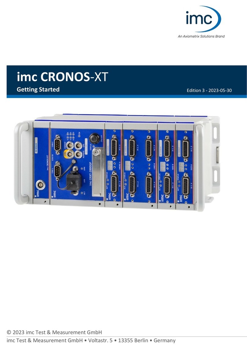
Axiometrix Solutions imc CRONOS-XT Getting started
