manuals.online logo
Brands
  1. Home
  2. •
  3. Brands
  4. •
  5. Nordic Auto Plow
  6. •
  7. Tractor Accessories
  8. •
  9. Nordic Auto Plow 18550 User manual

Nordic Auto Plow 18550 User manual

Nordic Auto Plow LLC
771 W. North Ave.
West Chicago IL 60185
Phone for customer service: 888-662-PLOW (7569)
E-mail: support@nordicautoplow.com
Website: nordicautoplow.com
866-941-6577 (Fax)
PLOW ASSEMBLY Steps: 1 2 3 4 5 6
MOWER ADAPTER ASSEMBLY Steps:
7
8 9 10
11
PLOW ATTACHMENT TO MOWER Steps: 12
ANGLE PLOWING ADJUSTMENTS Step: 13
UNIVERSAL LIGHT WEIGHT PLOW - RIDING MOWER
ASSEMBLY INSTRUCTIONS
BLADE SECTION
(3 - PIECES)
BLADE END
CAP
(2 - PIECES)
PLOW ASSEMBLY PARTS:
MOWER ADAPTER ASSEMBLY PARTS:
PLOW STRAP
(1 - PIECE)
BLOCK
(8 - PIECES)
BLADE CHANNEL
(2 - PIECES)
MOWER ARM
(2 - PIECES)
BOOT PLATE
(2 - PIECES)
TOP PIVOT PLATE
(1 - PIECE)
BOTTOM PIVOT
PLATE
(1 - PIECE)
AXLE
(1 - PIECE)
HARDWARE:
PIVOT BRACKET
(1 - PIECE)
COTTER PIN
(1)
T-HANDLE QUICK
RELEASE PIN (2)
USE FOR PLOW ASSEMBLY: USE FOR ADAPTER
AND PLOW
ATTACHMENT:
STEP - 11
ONLY
PAGE - 1
Place the Blade Sections face down and slide together as shown. A - Feed 1”
long bolts through 4 - fastening points. Attach washers and nuts, then finger
tighten only. Align Blade Sections and tighten fully.
WASHERS
AAAAA
AAAAA
AAAAA
AAAAA
AAAAA
1” LONG
X 4
X 4
3” LONG
IMPORTANT!
TIGHTEN FULLY
IMPORTANT!
TIGHTEN FULLY
TAB
Feed 3” long bolts through (2) holes in each End Cap and Blade Section.
Attach washers and nuts, tighten fully.
Place (8) Blocks over ends of the 3” long bolts as
shown. (Keep blocks and 3” long bolts in place for
the next step.)
1
2
43
LOCKING FACES OF LOCK
NUTS MUST ALWAYS BE IN
AGAINST THE SURFACE YOU
ARE FASTENING!
X 2
3/4” LONG
Position the Blade for front access. Screw 3/4”
self tapping Phillips screws into pilot holes at
(2) places as shown on the Blade front surface.
BLADE
X 8
3” LONG
PAGE - 2
X 4
NOTE: SLOT ON
TOP OF PLOW
NOTE: SLOT ON
TOP OF PLOW
Slide a Blade Channel (smaller flange at the top) over the top
(4) protruding bolt ends. Secure parts with (4) Keps nuts as
shown.
Slide a Blade Channel (smaller flange at the BOTTOM) over
the bottom (4) protruding bolt ends. Secure parts with (4) Keps
nuts as shown.
A- Attach the Bottom Pivot Plate (stamped “B”) centered, to the blade
channel with (2) 1” bolts, washers, and Keps nuts as shown.
B- Attach the Top Pivot Plate (stamped “T”) centered, to the other blade
channel with (2) 1” bolts, washers, and Keps nuts as shown.
BBBBB
BBBBA
6
7
5
BLADE CHANNEL
(SMALL FLANGE
UP)
BLADE CHANNEL
(SMALL FLANGE
DOWN)
1” LONG
PAGE - 3
REMOVE THE FRONT BUMPER (IF MOWER IS SO
EQUIPPED). Feed (2) 1” hex head bolts through
available holes from inside the mower frame.
Place Boot Plates outside of the Mower Arms. Line up holes in Boot Plates with
holes in Mower Arms. Feed (3) 1” long bolts through holes. Secure Boot Plates
to Mower Arms with (3) locking nuts each.
Using either side or end of the Mower Arm, slide
it over the bolts and secure with (2) lock nuts.
Repeat for opposite side of the mower.
89
10
1’ HEX HEAD BOLTS
(FROM INSIDE)
LOCKING FACES OF LOCK NUTS MUST
ALWAYS BE IN AGAINST THE SURFACE
YOU ARE FASTENING!
PAGE - 4
11
Feed the Axle through the holes in the Pivot Bracket which will allow the top edge of the plow to be
2” BACK FROM THE BOTTOM EDGE as shown in the “plow blade side view” above.
IMPORTANT: THE AXLE MUST BE 7“ UP FROM THE GROUND FOR PROPER PLOW OPERA-
TION. Secure the Axle with a cotter pin at the opposite end as shown.
IMPORTANT: Line up with holes on each side and insert the Axle so it is 7” ABOVE THE
GROUND. Lock the axle in place with a cotter pin from the opposite side.
For the (2) holes closest to the Mower: Use
the 1/2” x 1’ long bolts, nylon insert lock nuts,
with washers positioned as shown, and secure
from underneath as shown. Do not tighten fully,
but allow parts to pivot freely.
AXLE
AAAA2”
PLOW BLADE SIDE VIEW
AAAA7”
PIVOT BRACKET
PIVOT PLATES
ATTACHED TO
PLOW
12
PAGE - 5
14
Feed the Strap through the small slot at the top of the plow, and tie a
knot in it so it cannot be pulled through the slot. Bring free end of strap
up to handle bars. Pull on this strap to raise the plow.
STRAP
13
DISCHARGE TO RIGHT STRAIGHT PLOWING
DISCHARGE TO LEFT
PLOWING ANGLE SETTINGS ARE SHOWN ABOVE. For plow
discharging to the LEFT or RIGHT of the operator rotate the plow as
shown, line up holes in the Pivot Brackets with the hole in the Pivot
Plate, feed T - Handle Quick Release Pins through the appropriate
holes.
T-HANDLE QUICK
RELEASE PINS
PAGE - 6

Popular Tractor Accessories manuals by other brands

Spearhead TWIGA 500 Handbook

Spearhead

Spearhead TWIGA 500 Handbook

Tiger WILDKAT JD61 M/R Series manual

Tiger

Tiger WILDKAT JD61 M/R Series manual

Kubota BX25 Deluxe ROPS Cab installation manual
Kubota

Kubota BX25 Deluxe ROPS Cab installation manual

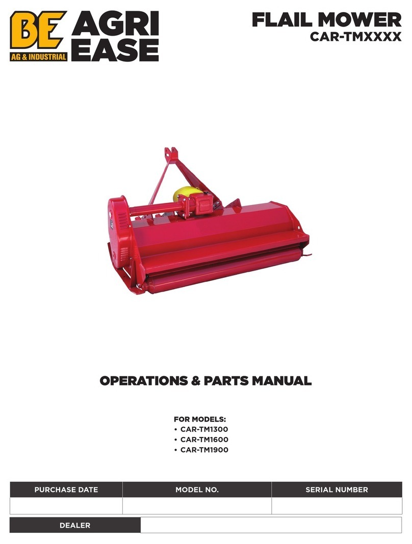
BE Ag & Industrial CAR-TM Series Operations & parts manual

BE Ag & Industrial

BE Ag & Industrial CAR-TM Series Operations & parts manual

Tiger NH T6 145-55/CASE MXM 125 Mounting and operating instructions

Tiger

Tiger NH T6 145-55/CASE MXM 125 Mounting and operating instructions

Maschio ORSO RAPIDO Series Use and maintenance

Maschio

Maschio ORSO RAPIDO Series Use and maintenance

Fransgard W-6011 manual

Fransgard

Fransgard W-6011 manual

HOLMS KHV 280 SMS bracket Operator instructions

HOLMS

HOLMS KHV 280 SMS bracket Operator instructions

McConnel 77 Series Operator's manual

McConnel

McConnel 77 Series Operator's manual

Redexim Extreme Clean II 1200 User manual and parts book

Redexim

Redexim Extreme Clean II 1200 User manual and parts book

Tiger WILDCAT JD6105D Mounting and operating instructions

Tiger

Tiger WILDCAT JD6105D Mounting and operating instructions

Rankin UBGS Operator's & parts manual

Rankin

Rankin UBGS Operator's & parts manual

Stark U-AURA Operating and maintenance manual

Stark

Stark U-AURA Operating and maintenance manual

MK Martin AXIS 4 Operator's & parts manual

MK Martin

MK Martin AXIS 4 Operator's & parts manual

Harvest TEC 601BB installation manual

Harvest TEC

Harvest TEC 601BB installation manual

Vicon CMP 3001A Operation manual

Vicon

Vicon CMP 3001A Operation manual

Grammer ACTIMO XXL operating instructions

Grammer

Grammer ACTIMO XXL operating instructions

Toro Greensmaster TriFlex 3300 Series Operator's manual

Toro

Toro Greensmaster TriFlex 3300 Series Operator's manual

manuals.online logo
manuals.online logoBrands
  • About & Mission
  • Contact us
  • Privacy Policy
  • Terms and Conditions

Copyright 2025 Manuals.Online. All Rights Reserved.