Rankin UBGS Programming manual

BALE GRABBERS
OPERATOR’S / PARTS MANUAL
Models: UBGS, USBG, UBG, USBG2C

LIMITED WARRANTY
RANKIN EQUIPMENT/NORTHSTAR ATTACHMENTS warrants each new
RANKIN/NORTHSTAR product to be free from defects in material and
workmanship for a period of twelve (12) months from date of purchase to the
original purchaser. This warranty shall not apply to implements or parts that
have been subject to misuse, negligence, accident, or that have been altered in
any way.
Our obligation shall be limited to repairing or replacement of any part, provided
that such part is returned within thirty (30) days from date of failure to RANKIN/
NORTHSTAR through the dealer from whom the purchase was made,
transportation charges prepaid.
This warranty shall not be interpreted to render us liable for injury or damages
of any kind or nature, direct, consequential or contingent, to person or property.
This warranty does not extend to loss of crops, loss because of delay in
harvesting or any other expenses, for any other reasons.
RANKIN/NORTHSTAR in no way warranties engines, tires, or other trade
accessories, since these items are warranted separately by these respective
manufacturers.
RANKIN/NORTHSTAR reserves the right to make improvements in design or
changes in specication at any time, without incurring any obligations to owners
or units previously sold.
RANKIN EQUIPMENT/NORTHSTAR ATTACHMENTS
3205 BAY STREET
UNION GAP, WA 98903
Always refer to and heed machine operating warning decals on machine.

Instruction Manual
UBG –Round bale grapple –1 hydralic cylinder
UBG2C - Round bale grapple –2 hydralic cylinder
UBGS - Round bale grapple SMART
USBG –Square bale grapple
Page 2z 35
NOTE!
Please read this Instruction Manual before you start operating the machine and observe all
safety rules contained herein.
The Instruction Manual constitutes the basic equipment of the machine!
Please keep this Instruction Manual in a safe place within easy reach of the user and the
operator during the whole period of machine use.
In case this manual is lost or damaged, you should purchase the new copy, by placing an order
in the point of sale or at the machine's manufacturer.
In case the machine is resold or made accessible to a third party, you should enclose
the Instruction Manual together with the Declaration of Conformity for the machine.
All the rights to this Instruction Manual are reserved by the manufacturer.
Copying, processing of this Instruction Manual or any of its part without the
manufacturer consent is forbidden.
The information contained in the manual is valid as at the date of preparation. Due to
product improvement, some informations and illustrations may not correspond to the actual
condition of the machine delivered to the customer. The manufacturer reserves the right to
introduce design changes improving the product, without making changes to this publication.
If the information contained in the manual are not fully understood, please refer to the
manufacturer or the point of sale.

Instruction Manual
UBG –Round bale grapple –1 hydralic cylinder
UBG2C - Round bale grapple –2 hydralic cylinder
UBGS - Round bale grapple SMART
USBG –Square bale grapple
Page 3z 35
Table of Contents
1. Introduction.............................................................................................................................................. 4
2. Operating safety rules .............................................................................................................................. 5
2.1 User safety.......................................................................................................................................... 5
2.2. Safety signs placed on the machine and their meaning.................................................................... 9
2.3. Risks occurring during grapple operation....................................................................................... 10
3. Intended use of the machine ................................................................................................................. 11
4. Machine description.............................................................................................................................. 12
4.1. Equipment and accessories............................................................................................................ 13
4.1.1. Basic......................................................................................................................................... 13
4.1.2. Auxiliary................................................................................................................................... 13
4.2. Technical specification ................................................................................................................... 14
4.3. Forces acting on the grapple........................................................................................................... 14
4.4. Assessing stability of a tractor with the machine attached ........................................................... 15
5. Machine use ........................................................................................................................................... 18
5.1. Grapple assembly ........................................................................................................................... 18
5.2. Hydraulic control system................................................................................................................ 19
6. . Operation and maintenance procedures ............................................................................................. 20
6.1 Scrapping, the environment............................................................................................................ 24
7. Spare parts catalogue............................................................................................................................ 25
7.1 Hydraulic supply elements ............................................................................................................... 29
8. Warranty................................................................................................................................................. 33
9. Declaration of Conformity...................................................................................................................... 35

Instruction Manual
UBG –Round bale grapple –1 hydralic cylinder
UBG2C - Round bale grapple –2 hydralic cylinder
UBGS - Round bale grapple SMART
USBG –Square bale grapple
Page 4z 35
1. Introduction
It is strongly recommended to read and understand this Instruction Manual before starting
operation of the grapple and observe all recommendations contained herein.
This Instruction Manual contains descriptions of all risks which may occur when you do not
observe safety rules during grapple work and operation. In this Instruction Manual safety
precautions which should be undertaken in order to minimise or avoid the risks are listed.
This Instruction Manual also contains the rules of proper grapple use and explains what service
procedures connected with it should be made.
If any information given in this Instruction Manual is incomprehensible, please ask directly the
manufacturer for an explanation.
NOTE !
Read this Instruction Manual
Before starting operation of the machine
NOTE !
This symbol warns about the risk.
This warning symbol indicates an important
information given in Instruction Manual concerning
the risk. Please read this information carefully,
comply with the instructions and act with due
caution.

Instruction Manual
UBG –Round bale grapple –1 hydralic cylinder
UBG2C - Round bale grapple –2 hydralic cylinder
UBGS - Round bale grapple SMART
USBG –Square bale grapple
Page 5z 35
2. Operating safety rules
2.1 User safety
The grapple may be operated exclusively by adults who have familiarized themselves with its
operation and who have read this Instruction Manual and have suitable qualifications.
When operating the grapple you should take all safety precautions, in particular:
•Observe general regulations relating to health and safety at work apart from keeping to
the recommendations included in this Instruction Manual.
•Follow the safety instructions of the warning symbols attached to the machine.
•Never permit other persons than the operator to drive the vehicle which operates the
grapple and do not allow other people to stay in the vehicle or on the machine during its
operation.
•The grapple may be operated only by a person who is authorized to drive a vehicle with
the grapple attached, in accordance with the manufacturer's recommendations.
•The work-stand of the operator during work with the grapple is the cabin of the vehicle
to which the grapple is attached.
•Please remember that there are a lot of places which can cause personal injury (sharp
edges, protruding construction elements etc.) on the grapple. When operating it you
should be particularly careful when you move near the above critical places, and you
absolutely must use personal protective equipment, such as:
- protective clothing,
- protective gloves,
- protective shoes
- protective helmet
•Transport of persons and objects other than fodder bales the grapple is intended for is
strictly forbidden.
•It is forbidden to operate the grapple by unauthorised persons who have not read this
Instruction Manual.
•An operator who operates the grapple must be equipped with first-aid-kit containing first
aid measures together with instructions of their use.
•When working with loose materials it is necessary to wear protective clothing suitable for
the material being transported, in particular: rubber boots, gloves, overall, cap and half-
mask.
•In case of poisoning or infection you should immediately contact the physician.
•When you drive the vehicle with the grapple not operated you should keep safety
transport clearance –min. 0.3 m.
•Transport speed should be adjusted to the condition of road surface. It should not exceed
8km/h.

Instruction Manual
UBG –Round bale grapple –1 hydralic cylinder
UBG2C - Round bale grapple –2 hydralic cylinder
UBGS - Round bale grapple SMART
USBG –Square bale grapple
Page 6z 35
•When working on company's area you should use outline electric lighting of the vehicle
and warning signalling device (yellow), and check their working order, cleanness and
visibility. You should attach in a visible way a triangular plate distinguishing slow-moving
vehicles on a machine or in the rear of the vehicle. Reflective light and warning signs
placed on machine's construction elements should be kept clean and visible.
•In order to keep suitable control, the grapple should be adjusted to the vehicle in
accordance with the recommendations of both the vehicle and the grapple
manufacturers as well as the suspension used. Manufacturer's clamping rules are
described in chapters . 4.4 Assessing stability of a tractor with the machine attached and
5.1. Grapple assembly.
•Please remember that during work with the grapple the load of vehicle steering axle
cannot be lower than 20% and the load of driving axle cannot be lower than 45% of total
weight.
•Never leave the vehicle with the grapple attached on slopes or other terrain inclinations
without protecting it against self-rolling downwards. The grapple should be lowered on
the ground. You should place wedges under the vehicle wheels.
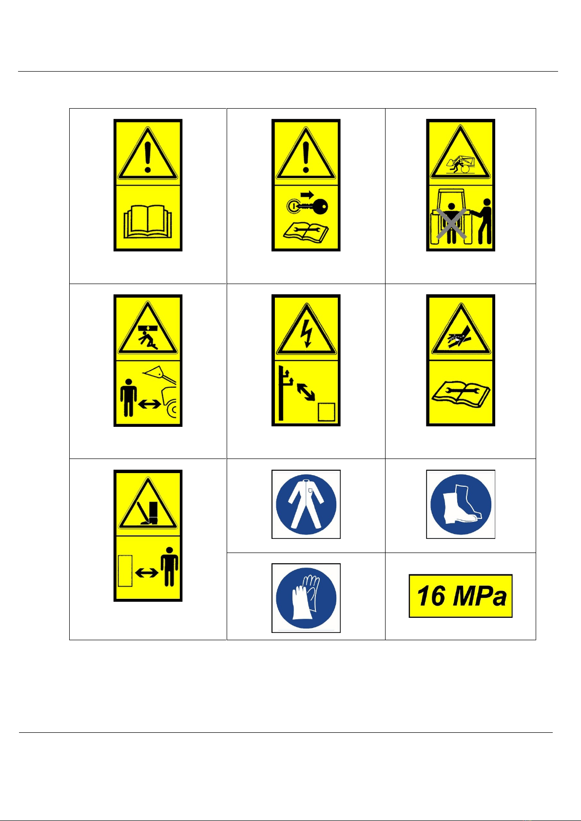
•Before you start any activity connected with preparation, assembly, disassembly or
adjustment you should stop the engine, switch off the drive, make the vehicle immobile
and wait until all moving parts of the machine stop and pressures cease.
•After the first hour of operation you should check the condition of all temporary
fastenings, e.g. bolted joints
•During grapple assembly and disassembly you should take special caution and be
especially careful about construction elements responsible for fastening it with the
vehicle.
•Before you start working with the grapple you should check its technical condition as well
as of a vehicle working with it. The vehicle and the grapple unit must be in good technical
condition. Worn and damaged parts should be immediately replaced with the new ones.
•The grapple must be equipped with all protective shields (if they are provided by the
manufacturer) which protect against accessing to movable parts. The protective covers
must be complete and in good working order.
•Weight of the grapple suspended on a vehicle may affect vehicle's manoeuvrability. In
such a situation great caution should be exercised.
•Keep this Instruction Manual accessible near the grapple. When you loan the grapple you
should hand it over in good working and technical condition along with the Instruction
Manual.
•Before you start working you should prepare the grapple in accordance with the
recommendations given in chapter: 5. Machine use, Grapple assembly.
•Lashing additional transport means to the grapple is strictly forbidden.

Instruction Manual
UBG –Round bale grapple –1 hydralic cylinder
UBG2C - Round bale grapple –2 hydralic cylinder
UBGS - Round bale grapple SMART
USBG –Square bale grapple
Page 7z 35
•It is forbidden to overload the grapple and to keep it loaded (e.g. keep the bale raised)
after finishing the work.
•Transport, moving with grapple attached on public roads is forbidden.
•When you start working with the grapple for the first time, you should check its
functioning.
•Assembly protections of the grapple bolts should be only done with the use of typical
protection means in the form of cotter pins. Work with other protective means is
forbidden.
•On account of natural wear of materials you should obey recommendations described in
chapter 6. Operation and maintenance procedures.
•Before you start to work, you should pay special attention to the condition of the grapple
hydraulic system. The cylinder, hydraulic piping and connections must be tight. Worn and
damaged parts should be immediately replaced with the new ones.
•In connection with ageing process –the lifetime of hydraulic lines should be not longer
than 4 years.
•During operation, hydraulic pipes are under high pressure. Assembly and disassembly of
the grapple hydraulic system with the vehicle should only be done with the vehicle engine
turned off, with hydraulic pressure in the grapple and vehicle hydraulic systems released.
•Upon receiving and transport of the grapple check its technical condition, whether it is
not damaged.
•Staying under the raised grapple is forbidden, there is a risk of being crushed by
construction elements or transported materials.
•Operator of the vehicle which works with the grapple must pay attention that no one
approaches the grapple or stays close to it during vehicle in operation.
•Don't put fingers and limbs between construction elements of the grapple while making
adjustments or overhaul.
•During turning or reversing, manoeuvring with the grapple, you should ensure suitable
visibility for yourself or look for help of a properly trained person.
•It is forbidden for operating personnel to stay between the vehicle and the grapple when
the vehicle's engine is operating.
•Work on the slopes exceeding 8% is inadmissible.
•During working on slopes you should act with great caution.
•Pay special attention during vehicle turns and manoeuvres with suspended grapple, both
during transport and while reversing, especially when people, animals or any objects are
close to the vehicle.
•The vehicle operating with the grapple should have cabin certified against falling objects
and additional safety cabin for the operator.

Instruction Manual
UBG –Round bale grapple –1 hydralic cylinder
UBG2C - Round bale grapple –2 hydralic cylinder
UBGS - Round bale grapple SMART
USBG –Square bale grapple
Page 8z 35
•Never leave the vehicle when the engine is operating. Before you leave the driver's seat
you should lower the grapple on the ground, turn off the vehicle engine, take out the
ignition key, operate the hand parking brake.
•Do not wear unbuttoned or loose-hanging work clothes while working, assembling,
disassembling or making adjustments. Keep them away from construction elements as
they may be caught by them.
•The grapple should be disconnected from the vehicle not earlier than after turning the
vehicle engine off and taking out the ignition key.
•After finishing work it is recommended to clean and wash the grapple in washing stand
fitted with sewage treatment or sediment trap to neutralize waste water.
•The grapple should be stored on flat, paved surface under a roof, in places protected
against unauthorised persons and animals, and in a way eliminating the risk of accidental
injury.
•In case of failure you should immediately disconnect the drive transmitted from the
vehicle.
•The grapple operation by people under an influence of alcohol, drugs or other narcotics
is strictly forbidden.
•All service procedures, which need a servicing person to stay near the grapple should be
done only with the grapple lowered on the ground and with the vehicle engine turned
off.
•The grapple control may be done only from the vehicle cabin, to which the grapple is
connected and after taking the seat by the operator.
Failure to follow the above instructions could cause a risk for the operator and
unauthorized persons, as well as damage the grapple. The user bears
responsibility for damages resulting from the lack of observing the above rules.
The grapple is not intended to travel on public roads –
transporting the grapple mounted on the tractor's suspension system during driving on
public roads is strictly forbidden.

Instruction Manual
UBG –Round bale grapple –1 hydralic cylinder
UBG2C - Round bale grapple –2 hydralic cylinder
UBGS - Round bale grapple SMART
USBG –Square bale grapple
Page 9z 35
2.2. Safety signs placed on the machine and their meaning
1.0 –Read this Instruction Manual
before you start operating the machine
C.2.26
1.1 –Turn off the engine and take out
the ignition key before starting service
works or repairs
C.2.7
1.5.1 –Don't take a seat close to lift
links during controlling the fork
C.2.1
1.2 –Keep safe distance from suspended
boom or bucket
C.2.30
1.7 –Keep safe distance from
the power lines
C.2.44
1.8 –Avoid action of fluid under high
pressure. Read the Instruction Manual
as regards service procedures
A.7.2 + B.2.6
1.2.2 –Keep safe distance from the
machine. Body and foot injury
2.3 –Wear protective overall
2.6 –Wear safety shoes
2.4 –Wear protective gloves
3.1 –Warning about existing pressure
in hydraulic circuit

Instruction Manual
UBG –Round bale grapple –1 hydralic cylinder
UBG2C - Round bale grapple –2 hydralic cylinder
UBGS - Round bale grapple SMART
USBG –Square bale grapple
Page 10 z 35
2.3. Risks occurring during grapple operation
No.
Risk
Source of risk (cause)
Possible causes of
the risk
Precautions
1
Excessive strain
of the motor
system (physical
strain)
Work in standing, forced
bent over position,
walking, sliding
Motor system diseases,
backbone injuries,
strained tendons
Familiarizing with Instruction Manual,
training at the work station with a
consideration of lifting standards during
manual transport works, proper weight
lifting techniques, using other person's
help, devices which make moving easier
e.g. hoist, hoisting winch
2
Falling down on
the same level
(stumbling,
slipping etc.)
Uneven ground, mess –
lying and standing
objects, communication
roads obstructed,
slippery surfaces of the
silos
Bruising, dislocations,
joint sprains, bone
fractures, injures
Suitable protective shoes, even ground,
focused attention, keeping order,
familiarizing with the Instruction Manual
3
Hitting on fixed,
protruding and
sharp machine
parts
The machine and its
environment
Body injures, bruising,
bumps, bruises, cuts
Proper placing of the machine, safe space
to move around, proper organization of
work, focused attention, use personal
protective equipment –protective helmet,
gloves, familiarizing with the Instruction
Manual
4
Hitting by moving
objects
Loose materials, fodders,
accidental turf parts,
silage falling down from
the machine during
transportation.
Bruising, cuts
Focused attention, marking of dangerous
zone, ban on moving nearby working
machine, ban on staying under suspended
weight - raised machine, wearing personal
protective equipment –protective helmet,
glasses, familiarizing with the Instruction
Manual
5
Sharp, dangerous
edges
Protruding machine
construction parts, use of
manual tools
Finger and hand
injuries, scratches,
catching loose clothes
on protruding parts
Personal protective equipment –
protective gloves, working uniform
buttoned up, focused attention
6
Movable machine
parts
Movable machine
elements, sliding piston
rods of hydraulic
cylinders, lack of movable
parts shielding
Dragging in, limb
injures, crushing of
fingers and palms
Ban on moving nearby working machine,
focused attention, use of movable parts
shields, familiarizing with the Instruction
Manual and use it.
7
Suspended and
standing machine
weight, loaded
machine weight,
load weight
Improper assembly,
aggregation, bad
positioning of the
machine, improper
organization and
operation, leaving the
suspended machine on
tractor, improper loading
of transported fodder,
the machine overloading
Bruising, feet and
palms crushing,
fractures
Focused attention, ban on staying under
suspended weight - raised machine, using
personal protective equipment - safety
boots, safety gloves, helmet, safe placing
of the machine, using other person's help,
using jacks, cranes, familiarizing with the
Instruction Manual. Proper, safe
organization of work.
8
Micro-climate –
changeable
atmospheric
conditions
Work done in differential
weather conditions
Overheating (thermal
shock), sun burnings
Suitable protective clothing, drinks, creams
with filters, taking breaks, familiarizing
with the Instruction Manual, vehicle cabin
ventilation
9
Noise
Too high revolutions of
the vehicle engine,
damaged, loose vibrating
parts of the machine
Irritation, lack of
concentration, neurosis
Work with the vehicle and the machine in
good working order, routine maintenance,
proper vehicle engine revolutions,
familiarizing with the Instruction Manual

Instruction Manual
UBG –Round bale grapple –1 hydralic cylinder
UBG2C - Round bale grapple –2 hydralic cylinder
UBGS - Round bale grapple SMART
USBG –Square bale grapple
Page 11 z 35
3. Intended use of the machine
Grapples fitted on machine and vehicle holders are designed for loading, unloading, collection,
storing of fodders, wastes, and transporting them on closed company's area. They are best
suited for bales of the following diameters:
The grapple assembly to the vehicle is possible with the use of the following fastenings: TUZ I,
TUZ II, TUZ III, EURO, SMS, ISO. The machine performs perfectly well after being fitted on all
frontal loaders of TUR type. The clamping system should be chosen in accordance with User
Manual of the vehicle and the grapple.
The working element is the grapple jaws, which due to their design, allow for easy gripping of
material and its transport. All types of grapples have hydraulic control system which after
connecting it enables smooth control of their operation from the vehicle operator's cabin.
Meeting the requirements concerning machine use, servicing and repairs in accordance with the
manufacturer's recommendations and strict observance of them is the condition of intended use
of the machine. The grapple should be used, operated and repaired exclusively by the persons
who know its characteristics and are familiarized with health and safety at work rules.
The manufacturer has a wide choice of grapples and other equipment, which make transport
easier. The manufacturer also offers specialist consultancy concerning the choice of suitable
equipment for customer's needs.
All cases of lack of clarity concerning the machine intended use, should be cleared
with the grapples manufacturer. Proper choice of the machine and awareness of
its intended use will rise safety at work.
Grapple type- INDEX
Range of bale diameters [m]
UBGS
0.80 ÷ 1.60
USBG
0.80 ÷ 2.10
UBG
0.90 ÷ 1.80
UBG2C
0.90 ÷ 1.80

Instruction Manual
UBG –Round bale grapple –1 hydralic cylinder
UBG2C - Round bale grapple –2 hydralic cylinder
UBGS - Round bale grapple SMART
USBG –Square bale grapple
Page 12 z 35
4. Machine description
Fig.1 General view ROUND BALE GRAPPLE SMART
The hydraulic driven grapples are adapted to work with a vehicle which has power hydraulic
system as a standard of the rear and front fastenings used in agricultural vehicles.
Basic tool fastening systems used in the case of grapples are as follows:
•TUZ I, TUZ II, TUZ III, TUZ IV hitch types
•EURO hitch
•SMS hitch
•ISO hitch
Each grapple is built of three articulated main construction elements. The first element –frame
is made of steel sections and thick steel plate made by laser cut method, welded to form a stiff
frame. The second and third element –arms are the movable parts of the grapple. They are
made of steel elements joined by welding. Their construction is adapted to the shape and size of
bales to be transported. It provides secure and safe grip. The hydraulic system which after being
connected to the vehicle is controlled from the operator's cabin allows for smooth work of the
arms in required range.

Instruction Manual
UBG –Round bale grapple –1 hydralic cylinder
UBG2C - Round bale grapple –2 hydralic cylinder
UBGS - Round bale grapple SMART
USBG –Square bale grapple
Page 13 z 35
4.1. Equipment and accessories
4.1.1. Basic
Basic equipment of the grapple includes:
•Hydraulic control system with power hydraulic system piping and hoses
•Instruction Manual
•Warranty card
Portable warning-lighting device and triangle marking plate for slow-moving
vehicles do not belong to the basic equipment of the grapples. You can buy them
at the manufacturer and in the agricultural machines depot for additional cost.
Each user of the grapple should have a warning-lighting device in good working
order and a triangle marking plate for slow-moving vehicles. Ignoring their use during transport
and work can result in accident. The machine user is responsible for damages resulting from an
accident.
4.1.2. Auxiliary
1. Linchpin, cotter pin, clip ø 10,5
Note:
ALL ELEMENTS OF AUXILIARY EQUIPMENT OF THE GRAPPLE MAY BE BOUGHT AT THE
MANUFACTURER FOR ADDITIONAL COST.

Instruction Manual
UBG –Round bale grapple –1 hydralic cylinder
UBG2C - Round bale grapple –2 hydralic cylinder
UBGS - Round bale grapple SMART
USBG –Square bale grapple
Page 14 z 35
4.2. Technical specification
Table No. 1 TECHNICAL DATA of BALE GRAPPLE
No
Specification
Unit of
measure
Parameter
1.
Grapple type- INDEX
-
UBGS
USBG
UBG
UBG2C
2.
Machine type
-
Suspended of medium class
3.
Overall dimensions
Length
Width
Height
[mm]
[mm]
[mm]
1200
1300
700
1100
1450
700
1370
1300
800
1370
1300
800
4.
Weight
[kg]
165
300
185
200
5.
Operating range - arms
spread
[m]
0.80 –1.60
0.80 –2.10
0.90 –1.80
0.90 –1.80
6.
Arms setup control
-
Hydraulic control system
7.
Grapple's load capacity -
max.
[kg]
1000*
8.
Hydraulic cylinder type
-
Two sided machining
9.
Hydraulic system
working pressure
[MPa]
10 ÷ 19
10.
Transport clearance
[mm]
300
11.
Transport speed
[km/h]
4 ÷ 8
12.
Number of personnel
[pcs.]
1
13.
Vehicle power demand
[HP]
from 48
*) –assuming permissible load capacity of vehicle lifting system
4.3. Forces acting on the grapple
Extreme phenomena occurring during operation with the grapple are comparable with impact
collision. To make the operation with the grapple easier the vehicle weight –carrier load
capacity has great significance. You should be aware of the forces which act during operation of
heavy vehicle with aggregated grapple. Reading and analysing Instruction Manual will
guarantee safe use and reduce the results of operation errors –it will lower a risk for operators.

Instruction Manual
UBG –Round bale grapple –1 hydralic cylinder
UBG2C - Round bale grapple –2 hydralic cylinder
UBGS - Round bale grapple SMART
USBG –Square bale grapple
Page 15 z 35
Table No. 2 Theoretical force Fmax [tonnes], which may act on grapple
clamped to the vehicle with the weight of 5000 kg with changeable speed
and braking distances.
The data concerning forces acting on the vehicle –grapple unit will require high level
of qualifications from persons operating the machine and appeal to consciousness
of hazards appearing during operation of grapples transporting bales with fodder.
It is essential to choose the safe vehicle driving speed in order to guarantee that the operation
does not constitute the risk for environment and operating personnel –the vehicle's operator.
It is of great importance to take care of even distribution of forces by the user as well as of
symmetrical pressure distribution of clamping arms. You should never operate the grapple with
only one arm loaded.
To prolong operation life of the grapple you should remember that the forces acting during
operation, both at gathering and clamping of grapple were evenly distributed.
4.4. Assessing stability of a tractor with the machine attached
In this paragraph the stability requirements of a tractor and the machine are presented as well
as a method of calculating required ballasts. Maximum permissible operating weights of the
machines are given in Table No. 1. The vehicle data may be found in its instruction manual.
The tractor coupled with the machine may lose its stability.
The weights of the machine and the tractor have to be properly chosen.
Before you start to work you must familiarize with stability assessment and
make sure that operation conditions given below are fulfilled.
If the machine stability requirements are not observed, this can lead to loss of
tractor's stability. It may create a risk of serious body injures or even death. You
should always take into account and observe stability requirements.
Breaking distance S
[m]
Vehicle speed V [km/h]
5
10
20
0.1
2
11
30
0.2
1
6
15
0.5
0.5
2.5
6
1.0
0.3
1
2.5

Instruction Manual
UBG –Round bale grapple –1 hydralic cylinder
UBG2C - Round bale grapple –2 hydralic cylinder
UBGS - Round bale grapple SMART
USBG –Square bale grapple
Page 16 z 35
PRESENTED CONDITIONS ARE BASED ON A MACHINE PLACED ON EVEN GROUND
Ignoring terrain inclinations or slopes may lead to loss of tractor's stability. It
may create a risk of serious body injures or even death. Ballast weights and
driving speed must be suitably adjusted, to ensure stable and accurate tractor's
drive ability and required brake effectiveness in critical situations.
Weights, loads [kg]:
MT - Weight without load
MTP - Maximum permissible weight with load
MF - Front axle load without load
MPF - Maximum permissible weight of front axle
MR - Rear axle load without load
MPR - Maximum permissible weight of rear axle
BF - Front axle equipment weight or ballast
BR - Rear axle equipment weight or ballast
Distances [m]:
a - between front load centre of gravity and the centre line of front axle
b - wheel base
c - from centre line of rear axle to lower hitch point of tree-point hitch.
d - between rear load centre of gravity to lower hitch point of hitch
e - between the rear axle centre line and the tractor's centre of gravity
Rys.2 Description of stability parameters
1.The accessory weight together with load should be added to the value at
load
2.Weight of fixed or fluid weights on the centre of front or rear wheels
should be added to the values MF, MR or MT
3.In case of non balanced trailer, value “c” is the distance between the rear
axle centre line and point of hitch, value “d” is equal to 0, while BR is the
vertical load of trailer on hitch
Minimum load of front axle of the tractor laden:
20% of gross vehicle weight MPT
Minimum load of the rear axle of the tractor laden:
45% of gross vehicle weight MPT

Instruction Manual
UBG –Round bale grapple –1 hydralic cylinder
UBG2C - Round bale grapple –2 hydralic cylinder
UBGS - Round bale grapple SMART
USBG –Square bale grapple
Page 17 z 35
Tabel No. 3. Calculations of required ballasts
REQUIRED BALLAST IN FRONT
REQUIRED BALLAST ON THE REAR
BRr –ballast required on the front during transport
of BF load on the rear
BRr –ballast required in the rear during transport
of BF load in the front
MT · e = MF · b e = (MF · b)/MT
MT · (b – e) = MR · b
BR · (c + d) - (MT · e) + (MPF · b) = BFr · (a +b)
BF · a - MT · (b - e) + (MPR · b) = BRr · (b + c + d)
MPF > 0,2 · MT
Maximum permissible weight of front axle must be greater
than 0.2 × vehicle curb weight without load
MPR > 0.45 · MT
Maximum permissible weight of the rear axle must be greater
than 0.45 × vehicle curb weight without load
BFr > [BR·(c+d) - (MF·b) + (0,2·MT·b)] / (a+b)
BRr > [(BF·a) - (MR·b) + (0,45·MT·b)] / (b +c +d)
You should read the Instruction Manual of the vehicle (tractor), get to know
maximum axle load and fulfil the below conditions, so as to achieve:
MPF < MPFmax of the tractor
MPR < MPRmax of the tractor
MPT < MPTmax of the tractor
Table No. 4. Calculations of maximum permissible weights
MAXIMUM PERMISSIBLE
LOAD OF FRONT AXLE MPF
MAXIMUM PERMISSIBLE
LOAD OF REAR AXLE MPR
GROSS VEHICLE WEIGHT OF
LOADED VEHICLE MPT
MPF = [BF·(a+b)+(MF·b)-BR·(c+d)]/b <
MPFmax
MPR=MPT –MPF < MPRmax
MPT=BF + MT + BR < MPTmax

Instruction Manual
UBG –Round bale grapple –1 hydralic cylinder
UBG2C - Round bale grapple –2 hydralic cylinder
UBGS - Round bale grapple SMART
USBG –Square bale grapple
Page 18 z 35
5. Machine use
5.1. Grapple assembly
Make sure that all mounting elements of the vehicle and the grapple are matched
appropriately to guarantee safe assembly and operation.
In case of the lack of clarity you should definitely contact the manufacturer of the
vehicle or the grapple.
As there is a need to connect two grapple systems to the vehicle, the assembly of the grapple
should be done in the following order:
I. Assembly of mechanical system of the vehicle and the grapple.
Depending on the type of fastening system, you should provide original protections. Every time
when you assembly the system you should check the wear of connecting elements: bolts,
journals, cotter pins, pins and screw connections.
II. Assembly of the power hydraulic system
The grapple is equipped with pipes (hoses), which need to be connected to connector pipes of
the vehicle power hydraulic system. Make sure that the pipes (hoses) are run properly and check
hydraulic connectors cleanliness. Connection should be made in accordance with schematic
drawing 3
The grapple dismantling is carried out in reverse order with exercising special
caution during disassembly of mechanical system which separates the grapple
from the vehicle.

Instruction Manual
UBG –Round bale grapple –1 hydralic cylinder
UBG2C - Round bale grapple –2 hydralic cylinder
UBGS - Round bale grapple SMART
USBG –Square bale grapple
Page 19 z 35
5.2. Hydraulic control system
The grapple arms pressure operation is controlled from the vehicle operator cabin. The grapples
are equipped with power hydraulic system hoses with terminals which after being connected to
the power hydraulic system of the vehicle ensure smooth control of their work.
UBGS and UBG grapples
USBG and UBG2C grapples
Fig.3 The grapples hydraulic systems
This manual suits for next models
3
Table of contents
Other Rankin Tractor Accessories manuals
Popular Tractor Accessories manuals by other brands

Vicon
Vicon CMP 3001F Operation manual

Raven
Raven SmarTrax installation manual

Grammer
Grammer ACTIMO XL operating instructions

Original Tractor Cabs
Original Tractor Cabs 12168 Parts List & Assembly Instructions

Harvest TEC
Harvest TEC 602 Operation manual

Buyers Products Company
Buyers Products Company PW22 Pro-Wings installation instructions