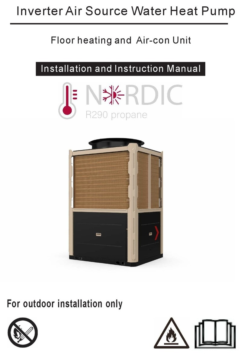
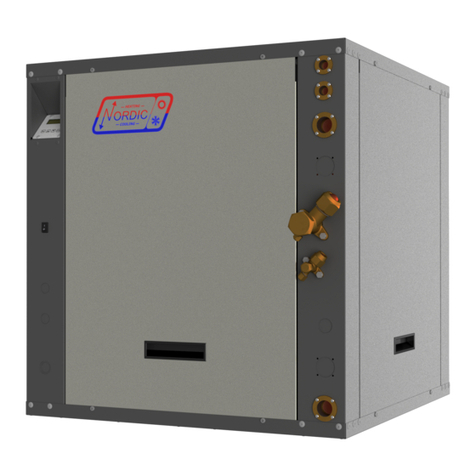
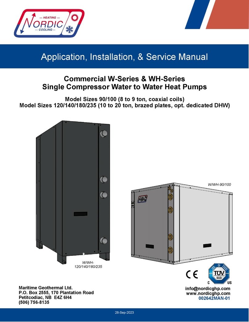
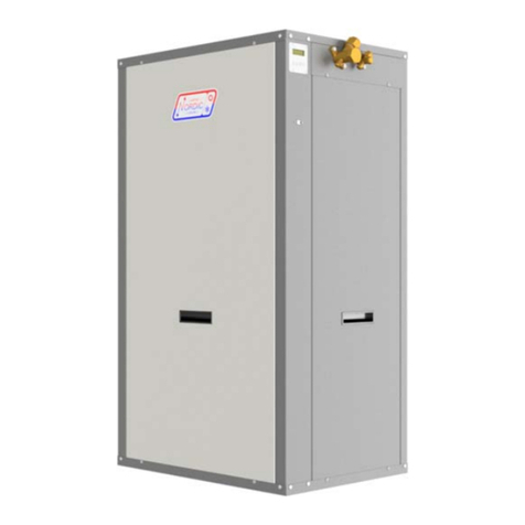
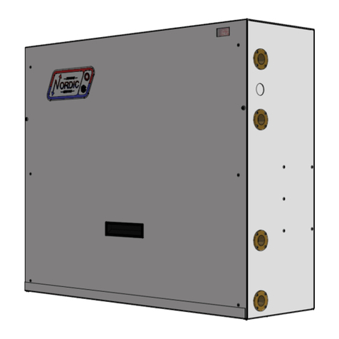
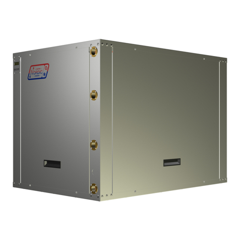
Nordic W Series Manual

1-Apr-2021 Page 1 002507MAN-01
Maritime Geothermal Ltd.
P.O. Box 2555, 170 Plantation Road
Petitcodiac, NB E4Z 6H4
(506) 756-8135
W-Series
Liquid to Water Heat Pumps
Single-Stage R410a
Model Sizes 12-18
www.nordicghp.com
002507MAN-01
1-Apr-2021
Installation and Service Manual

1-Apr-2021 Page 2 002507MAN-01
W—18—HAC—P—1L—CP—xx
WARNING: Ensure all access panels are in place and properly secured before applying power to the unit.
Failure to do so may cause electrical shock.
WARNING: Before performing service or maintenance on the heat pump system, ensure all power sources
are DISCONNECTED. Electrical shock can cause serious personal injury or death.
WARNING: Heat pump systems contain refrigerant under high pressure and as such can be hazardous to
work on. Only qualified service personnel should install, repair, or service the heat pump.
CAUTION: Safety glasses and work gloves should be worn at all times whenever a heat pump is serviced.
A fire extinguisher and proper ventilation should be present whenever brazing is performed.
CAUTION: Venting refrigerant to atmosphere is illegal. A proper refrigerant recovery system must be
employed whenever repairs require removal of refrigerant from the heat pump.
SAFETY PRECAUTIONS
Model Nomenclature
Series:
W = liquid to water (hydronic)
Nominal Size:
12 = 1 ton
15 = 1.25 ton
18 = 1.5 ton
Functions:
H = Heating
AC = Active Cooling
Refrigerant:
P = R410a
Voltage Code:
1 = 208/230-1-60
3 = 265/277-1-60
6 = 220-1-50
Compressor:
L = single stage rotary
Outdoor Loop Exchanger:
C = Copper coaxial
Z = CuNi coil only
Indoor Loop Exchanger:
P = brazed plate
Revision:
01, 02 etc.

1-Apr-2021 Page 3 002507MAN-01
Maritime Geothermal Ltd. has a continuous improvement policy and reserves the right to modify specification
data at any time without prior notice .
APPLICATION TABLE
MODEL FUNCTION REFRIGERANT VOLTAGE COMPRESOR OUTDOOR
COIL
INDOOR
COIL REVISIONS
W-12 HAC P 1
3 L C
Z P 01
W-15 HAC P 1
3 L C
Z P 01
W-18 HAC P 1
3 L C
Z P 01
This manual applies only to the models and revisions listed in this table

1-Apr-2021 Page 4 002507MAN-01
Tables, Figures, & Documents ....................................... 5
W-Series System Description ........................................ 6
General Overview ................................................................... 6
1. Heating Mode ..................................................................... 6
2. Cooling Mode ...................................................................... 6
W-Series Sizing .................................................................. 7
Heat Pump Sizing ................................................................... 7
Auxiliary Heat Sizing ............................................................... 7
Installation Basics ............................................................. 8
Sample Bill of Materials - Ground Loop Installations .............. 8
Sample Bill of Materials - Open Loop Installations .................. 8
Unpacking the unit .................................................................. 8
Unit Placement ....................................................................... 8
Wiring ................................................................................... 9
Power Supply Connections ..................................................... 9
Indoor Loop Circulator Pump Wiring ....................................... 9
Outdoor Loop Pump Module Wiring (Ground Loop Only) ....... 9
Control Transformer ................................................................ 9
Open/Closed Loop Wiring ....................................................... 9
Control Requirements ............................................................ 10
Manual Cooling Mode Switchover ......................................... 10
Auxiliary Heat ........................................................................ 10
Internal Aquastat Operation .................................................. 10
Safety Controls ..................................................................... 11
002508CDG - Typ. Aux Heat & Circ. Wiring w/Int. Aquastat . 12
002375QSS - AltSource Tanks: Getting Started ................... 13
002067CDG - Typical Zone Wiring (Heating Only) ............... 14
002509CDG - Typ. Control & Zone Wiring (Htg & Cooling) .. 15
Piping ................................................................................. 16
Indoor Loop ........................................................................... 16
Outdoor Loop ........................................................................ 16
002366PDG - Recommended Hydronic Buffer Tank Piping .. 17
002367PDG - Auxiliary Boiler Piping ..................................... 18
002252PDG - 2-Tank System with a Reversing Heat Pump .. 19
002288PDG - 2-Tank Simultaneous Heating/Cooling ............ 20
002506PDG - Space Cond. & DHW Htg w/2 Heat Pumps ..... 21
000530PDG - Typical Zone Types ......................................... 22
Ground Loop Installations ............................................ 23
Circulator Pump Module ....................................................... 23
Flushing & Purging ............................................................... 23
Adding Antifreeze Solution .................................................... 24
Initial Pressurization .............................................................. 24
Pipe Insulation ...................................................................... 24
000608INF - Typical Horiz. Ground Loop Configuration ........ 25
000609INF - Typical Vert. Ground Loop Configuration .......... 26
000906CDG - Circulator Pump Module Installation .............. 27
000629PDG - Pump Module Inst - 2 Units on 1 Loop ........... 28
Open Loop Installations ................................................ 29
Well Water Temperature ....................................................... 29
Well Water Flow .................................................................... 29
Well Water Quality ................................................................ 29
Water Discharge Methods .................................................... 29
Water Valve .......................................................................... 30
Water Flow Control ............................................................... 30
Submersible Pump Selection ................................................ 31
Submersible Pump Power Draw ........................................... 31
Plumbing the Heat Pump ...................................................... 31
Pipe Insulation ...................................................................... 31
000907CDG - Typical Open Loop Installation ....................... 32
000619INF - Ground Water Disposal Methods ..................... 33
Table of Contents
Startup Procedure ........................................................... 34
Pre-start Inspection ............................................................... 34
Unit Startup ........................................................................... 35
Startup Record ...................................................................... 36
General Maintenance ...................................................... 37
Troubleshooting Guide .................................................. 38
Repair Procedures .......................................................... 44
Pumpdown Procedure .......................................................... 44
General Repair Procedure .................................................... 44
Vacuuming & Charging Procedure ....................................... 44
Compressor Replacement Procedure ................................... 45
Model Specific Information ........................................... 46
Refrigerant Charge ............................................................... 46
Shipping Information ............................................................. 46
Operating Temperature Limits .............................................. 46
Required Indoor & Outdoor Loop Flow Rates ....................... 46
Electrical Specifications ........................................................ 46
Pressure Drop Data .............................................................. 47
Standard Capacity Ratings .................................................... 48
Performance Tables: W-12 .................................................... 49
Performance Tables: W-15 .................................................... 50
Performance Tables: W-18 .................................................... 51
Wiring Diagram (208/230-1-60) ............................................ 52
Wiring Diagram (265/277-1-60) ............................................ 53
Refrigeration Circuit - Heating Mode ..................................... 54
Refrigeration Circuit - Cooling Mode ..................................... 55
Dimensions ........................................................................... 56
Warranty ............................................................................ 57

1-Apr-2021 Page 5 002507MAN-01
Tables, Figures, & Documents
Table 1 - Heat Pump Size vs. Heated Area for a Ground Loop System .................................................. 7
Table 2 - Heat Pump Size vs. Heated Area for an Open Loop System ................................................... 7
Table 3 - Auxiliary Heat Sizing ................................................................................................................ 7
Table 4 - Power Supply Connections ...................................................................................................... 9
Table 5 - Indoor & Outdoor Circulator Connections ................................................................................. 9
Table 6 - Control Signal Description ...................................................................................................... 10
Table 7 - Internal Aquastat Settings ...................................................................................................... 10
Table 8 - Typical Aquastat Setpoints ..................................................................................................... 10
Table 9 - Control Board Fault Codes ..................................................................................................... 11
Table 10 - Buffer Tank Size ................................................................................................................... 16
Table 11 - Antifreeze Percentages ........................................................................................................ 24
Table 12 - Volume of Fluid per 100ft. Of Pipe ....................................................................................... 24
Table 13 - Required Flow ...................................................................................................................... 29
Table 14 - Refrigerant Charge ............................................................................................................... 46
Table 15 - Shipping Information ............................................................................................................. 46
Table 16 - Operating Temperature Limits .............................................................................................. 46
Table 17 - Required Indoor & Outdoor Loop Flow Rates ....................................................................... 46
Table 18 - Electrical Specifications ........................................................................................................ 46
Table 19 - Loop Pressure Drop Data ..................................................................................................... 47
Table 20 - Standard Capacity Ratings - Ground Loop Heating 60Hz .................................................... 48
Table 21 - Standard Capacity Ratings - Ground Loop Cooling 60Hz .................................................... 48
Table 22 - Standard Capacity Ratings - Ground Water Heating 60Hz ................................................... 48
Table 23 - Standard Capacity Ratings - Ground Water Cooling 60Hz ................................................... 48
Figure 1 - Ground Loop Accessories & Tools ........................................................................................ 23
Figure 2 - Open Loop Accessories & Tools ........................................................................................... 30
Dimensions ............................................................................................................................................ 56
002508CDG - Typical Auxiliary Heat & Circulator Wiring w/ Internal Aquastat ....................................... 12
002375QSS - AltSource Tanks: Getting Started .................................................................................... 13
002067CDG - Typical Zone Wiring (Heating Only) ................................................................................ 14
002509CDG - Typical Control & Zone Wiring (Heating & Cooling, Automatic Switchover) .................... 15
002366PDG - Recommended Hydronic Buffer Tank Piping ................................................................... 17
002367PDG - Auxiliary Boiler Piping ...................................................................................................... 18
002252PDG - Two Tank System Piping with a Reversing Heat Pump ................................................... 19
002288PDG - Two Tank Simultaneous Heating / Cooling ...................................................................... 20
002506PDG - Space Conditioning & DHW Heating with Two NORDIC Heat Pumps............................. 21
000530PDG - Typical Zone Types for Hydronic Applications ................................................................. 22
000608INF - Typical Horizontal Ground Loop Configuration .................................................................. 25
000609INF - Typical Vertical Ground Loop Configuration ...................................................................... 26
000906CDG - Geo-Flo Circulator Pump Module Installation ................................................................. 27
000629PDG - Circulator Pump Module Installation - Two Units on One Ground Loop........................... 28
000907CDG - Typical Ground Water (Open Loop) Installation ............................................................. 32
000619INF - Ground Water Disposal Methods ...................................................................................... 33
002380SCH - W-HAC Schematic Diagram 208/230-1-60 Rotary Reversing ......................................... 52
002383SCH - W-HAC Schematic Diagram 265/277-1-60 Rotary Reversing ......................................... 53
001488RCD - W-Series Refrigeration Circuit - Heating Mode ............................................................... 54
001489RCD - W-Series Refrigeration Circuit - Cooling Mode ............................................................... 55
Tables
Figures
Documents

1-Apr-2021 Page 6 002507MAN-01
W-Series System Description
General Overview
The Nordic W-series, a geothermal standard for more than
30 years, is a package water source heat pump that can heat or
chill water for hydronic applications like in-floor heating, low
temperature radiators, or hydronic air handlers/fan coils.
Being a ‘ground source’, ‘water source’, ’geoexchange’, or
‘geothermal’ heat pump, the W-series does require either a
closed ground loop or open loop water well for a heat
source/sink. There is no outdoor fan unit for ground source heat
pumps.
The outdoor loop hydronic heat exchanger is a heavy duty
coaxial copper / steel model with optional CuNi inner tube avail-
able. The indoor loop heat exchanger is a stainless steel
brazed plate model, for compact size and high heating perfor-
mance. Compressor is a single-stage rotary model. A single
thermostatic expansion valve (TXV) regulates superheat. The
cabinet is constructed from powder coated galvanized sheet
metal, and is a slim style that can be wall mounted.
Most or all water to water heat pumps on the market start
at 2 tons in nominal size, making them too large for single zone,
decentralized, or passive home applications. The model sizes
described here are 1-1.5 tons in size, making them ideal for
such applications.
1. Heating Mode
In heating mode, the heat pump heats water in a buffer
tank to a user-adjustable setpoint temperature, while extracting
heat from the outdoor loop. A buffer tank is required, in order
to maintain control over the water temperature and avoid mis-
matching between the heat pump’s output and the heat load. A
built-in aquastat determines when the buffer tank temperature
has fallen below the user-adjustable setpoint and hydronic heat-
ing is required. An external backup heating device can be acti-
vated through dry contacts via a built-in 0-2 hour timer.
If a closed ground loop is used, the circulation pumps are
powered and controlled by the heat pump; if open loop, a water
valve is opened by the heat pump during heating operation and
closed when the heat pump is idle.
Hydronic heating systems are easily zoned, and zones
may be in-floor heating, hydronic air handlers, or other hydronic
devices suitable for water temperatures less than 120°F (49°C).
When a zone requires heat, its zone thermostat calls for a zone
circulator pump or zone valve to activate, so that hot water from
the buffer tank is sent to the zone requiring heat. Note that
there is no direct connection between the zone thermostat and
the heat pump, the functions of each being separated by the
buffer tank.
2. Cooling Mode
In cooling mode, the heat pump cools water in the buffer
tank. Heat is rejected to the outdoor loop.
Hydronic cooling is usually done through hydronic air han-
dlers, which have condensate drains to remove water that is
removed while dehumidifying the air. In less humid climates or
when a separate dehumidifier is present, in-floor or radiant cool-
ing is sometimes performed; such systems can’t remove humidi-
ty from the air. In this case, care must be taken to ensure the
cooling surface does not fall below the dew point temperature in
order to prevent condensation on floor surfaces.
Installation example of a larger (W 25-80) Nordic water to water heat pump

1-Apr-2021 Page 7 002507MAN-01
W-Series Sizing
Heat Pump Sizing
The following table is a rough guideline as to the size of
space each heat pump size can handle for ground loop (closed
loop) installations.
The following table is a rough guideline as to the size of
home each heat pump size can handle for ground water (open
loop) installations.
THE TABLES ABOVE ARE FOR INFORMATION ONLY.
They should not be used to select a final unit size. They
simply show on average what size unit is required for a typical
space or home (main level and below grade basement) with
R20 walls, R40 ceiling and average size and number of win-
dows. The Heated Area is the area of the main level. The ta-
bles account for a basement the same size as the heated area.
IT IS HIGHLY RECOMMENDED THAT A PROPER HEAT
LOSS/GAIN ANALYSIS BE PERFORMED BY A PROFES-
SIONAL WITH APPROVED CSA F-280 SOFTWARE BEFORE
SELECTING THE SIZE OF UNIT REQUIRED FOR THE APPLI-
CATION. For heating dominant climates, we recommend
sizing the unit to 100% of the heating design load for maxi-
mum long term efficiency with minimal supplementary heat.
The unit should be installed as per CSA standard 448.2-02.
For ground loop applications, the ground loop should be
designed using suitable software with a multi-year analysis.
The analysis will result in a heat load for the coldest day,
which is influenced by, for example, the number of levels, the
size of the windows, the orientation of the home, attached gar-
age, bonus rooms, walk-in basement, and coldest outdoor tem-
perature for the region.
A heat pump model size can be selected by comparing the
calculated heat load to the standard capacity ratings, which are
listed in the Model Specific Information section of this manual.
For 100% heat pump sizing, choose a heat pump with a stand-
ard capacity rating that matches or just slightly exceeds the cal-
culated heat load.
Closed ground loops are normally designed to reach a
minimum temperature of just below freezing at the end of the
heating season, in order to take advantage of the latent heat of
groundwater (at least in northern climates). Hence, the Stand-
ard Capacity Ratings for Ground Loop Heating should apply in
all northern climates.
The Standard Capacity Ratings for Ground Water (open
loop) heat pumps assume a well water temperature of 50°F (10°
C). If the groundwater is not close to this temperature, it will be
necessary to consult the more detailed performance tables later
in the section for heat pump output at a different Entering Liquid
Temperature (ELT).
In cooling dominant climates, the heat pump should be
similarly sized using the Ground Loop Cooling or Ground Water
Cooling Standard Capacity Ratings. Even in northern heating
dominant climates, it should be ensured that 100% of the
cooling load will be covered when sizing the heat pump,
since there is normally no auxiliary or backup cooling avail-
able.
Auxiliary Heat Sizing
The easiest way to provide auxiliary or backup heat for
new installations is by installing a buffer tank that has electric
elements. Buffer tanks with elements that are certified for space
heating use are available as accessories from Maritime Geo-
thermal Ltd., or others may be used. For retrofits, often an ex-
isting heat device can be used for auxiliary heat. Note that if the
geothermal heat pump is sized for 100% of the coldest day heat
load, auxiliary heat is not strictly required (unlike with an air
source heat pump).
For full backup, an option which is good for peace of mind
(should the heat pump experience a problem) but can require
significant electrical service capacity, an element size can be
chosen that covers 100% of the coldest day heat load, accord-
ing to the heat loss analysis mentioned in the last section. If a
heat loss analysis is not available, the following table may be
used as a guide.
For heat pumps that are sized to cover less than 100% of
the coldest day heat load, the elements can be sized to make up
the coldest-day difference. The CSA installation standard al-
lows geothermal heat pumps to be sized to as little as 75% of
the coldest day heat load.
For retrofits, the existing heating device (e.g. an electric or
gas boiler) may be used for auxiliary heat. It should be wired as
described in the Wiring section, and piped in a parallel arrange-
ment as per the diagram in the Piping section.
TABLE 1 - Heat Pump Size vs. Heated Area for
a Ground Loop System
Model Size ft2 m2
12 400 37
15 475 44
18 600 56
TABLE 2 - Heat Pump Size vs. Heated Area
for an Open Loop System
Model Size ft2 m2
12 500 47
15 575 53
18 750 70
TABLE 3 - Auxiliary Heat Sizing
Model Size Tank Element Size
Recommended
12 3000 W
15 3500 W
18 5000 W

1-Apr-2021 Page 8 002507MAN-01
Sample Bill of Materials -
Ground Loop Installations
Although not exhaustive, following is a list of materials needed
for a typical ground loop installation:
FROM MARITIME GEOTHERMAL
• W SERIES HEAT PUMP
• BUFFER TANK W/ELEMENTS __kW
• EXTERNAL AQUASTAT (ONLY FOR HEAT/COOL AUTO
SWITCHOVER CONFIGURATIONS)
• P/T PORTS AND HOSE ADAPTERS (2)
• PUMP PACK
• PIPE ADAPTERS FOR PUMP PACK
OPTIONAL FROM MARITIME GEOTHERMAL
• ANTI-VIBRATION PAD
• SOUND JACKET
• AHW-65 AIR HANDLER(S)
GROUND LOOP
• ¾” PE PIPE
• 1-1/4” PE PIPE
• PE PIPE FITTINGS
• 1” CLEAR HOSE (HEAT PUMP TO PUMP PACK)
• HOSE CLAMPS
• ANTIFREEZE: METHANOL OR PROP. GLYCOL
ZONES
• CIRCULATOR: HEAT PUMP TO TANK
• 3/4” PIPE & FITTINGS: HEAT PUMP TO TANK
• ZONES CIRCULATOR(S)
• ZONE TRANSFORMER & CIRC CONTACTOR
• ZONE VALVES (IF NOT INDIVIDUAL PUMPS)
• IN-FLOOR PIPING
• OTHER AIR HANDLERS, DUCTING
• ZONE THERMOSTATS
• RELAYS OR ZONE CONTR. (REVERSING SYSTEMS)
• ZONE SUPPLY & RETURN HEADERS
• PIPE & FITTINGS TO ZONES
• EXPANSION TANK
ELECTRICAL
• HEAT PUMP SERVICE WIRE
• BUFFER TANK ELEMENT SERVICE WIRE
• HEAT PUMP BREAKER
• BUFFER TANK ELEMENT BREAKER
• CONTACTOR & ELEC. BOX (IF NOT WITH TANK)
• THERMOSTAT WIRE 18-4
• THERMOSTAT WIRE 18-2
• FORK TERMINALS FOR TSTAT WIRE (6)
• 2” STYROFOAM INSUL. (IF PAD NOT PURCHASED)
Sample Bill of Materials -
Open Loop Installations
Although not exhaustive, following is a list of materials needed
for a typical open loop (groundwater) installation:
FROM MARITIME GEOTHERMAL
• W SERIES HEAT PUMP
• BUFFER TANK W/ELEMENTS __kW
• EXTERNAL AQUASTAT (ONLY FOR HEAT/COOL AUTO
SWITCHOVER CONFIGURATIONS)
• P/T PORTS AND HOSE ADAPTERS (2)
• DOLE VALVE
• TACO OR SOLENOID VALVE
OPTIONAL FROM MARITIME GEOTHERMAL
• ANTI-VIBRATION PAD
• SOUND JACKET
• AHW-65 AIR HANDLER(S)
WATER SYSTEM
• 3/4” BLACK PLASTIC WATER PIPE
• 3/4” BARBED FITTINGS & HOSE CLAMPS
• SUBMERSIBLE PUMP (IF NOT EXISTING)
• PRESSURE TANK (IF NOT EXISTING)
• CYCLE STOP VALVE (OPTIONAL)
ZONES
• CIRCULATOR: HEAT PUMP TO TANK
• 3/4” PIPE & FITTINGS: HEAT PUMP TO TANK
• ZONES CIRCULATOR(S)
• ZONE TRANSFORMER & CIRC CONTACTOR
• ZONE VALVES (IF NOT INDIVIDUAL PUMPS)
• IN-FLOOR PIPING
• OTHER AIR HANDLERS, DUCTING
• ZONE THERMOSTATS
• RELAYS OR ZONE CONTR. (REVERSING SYSTEMS)
• ZONE SUPPLY & RETURN HEADERS
• PIPE & FITTINGS TO ZONES
• EXPANSION TANK
ELECTRICAL
• HEAT PUMP SERVICE WIRE
• BUFFER TANK ELEMENT SERVICE WIRE
• HEAT PUMP BREAKER
• BUFFER TANK ELEMENT BREAKER
• CONTACTOR & ELEC. BOX (IF NOT WITH TANK)
• THERMOSTAT WIRE 18-4
• THERMOSTAT WIRE 18-2
• FORK TERMINALS FOR TSTAT WIRE (6)
• 2” STYROFOAM INSUL. (IF PAD NOT PURCHASED)
Installation Basics
Unpacking the Unit
When the heat pump arrives it should be unpacked to
determine if any damage has occurred during shipment. Any
visible damage should be noted on the carrier's freight bill and a
suitable claim filed.
Unit Placement
The placement of a hydronic heat pump has negligible
effects on the efficiency and operation of the system. The hy-
dronic layout may make a particular location ideal for the unit.
The heat pump is designed to be wall-mounted. See the
Dimensions section toward the end of this document for
mounting bolt pattern on wall. Four 5/16” lag bolts into solid
wood or equivalent must be used to carry the significant weight
of the heat pump and water in heat exchangers.
The heat pump cover should remain unobstructed for a
distance of two feet to facilitate servicing and general
maintenance.
If floor mounted, provision should be made to eliminate
tipping hazard. Raising the indoor unit off the floor a few inches
is generally a good practice since this will prevent rusting of the
bottom panel of the unit and deaden vibrations. A piece of 2”
Styrofoam can be placed under the unit.

1-Apr-2021 Page 9 002507MAN-01
Wiring
Power Supply Connections
Power supply for the heat pump from the breaker panel is
supplied to the unit via a 0.875” knockout. There are also two
0.875” knockouts for electrical connections to the indoor circula-
tor, ground loop circulator pump, and controls. There is one
additional 1/2” opening with plastic grommet (grommet hole is
3/8”) for connections to the controls.
A schematic diagram (SCH) can be found on the electrical
box cover of the unit as well as in the Model Specific Infor-
mation section of this manual. The Electrical Specifications
table in the Model Specific Information section contains infor-
mation about the wire and breaker size.
Outdoor Loop Pump Module Wiring
(Ground Loop Only)
The heat pump has provisions for connecting the circulator
pump module so that the pumps will be turned on whenever the
compressor operates. Connect the circulator pump module to
the appropriate two terminals (115V or 230V) of the terminal
strip marked OUTDOOR - INDOOR CIRCULATORS in the
heat pump, as per the voltage of the circulator pump module.
Ground wire should be connected to the ground lug in the elec-
trical box. Ensure that the total current draw does not exceed
the value indicated on the label in the heat pump electrical box.
IMPORTANT NOTE: A properly qualified
electrician should be retained for all
connections to the heat pump and associat-
ed controls. The connections to the heat
pump MUST CONFORM TO LOCAL CODES.
TABLE 4 - Power Supply Connections
Line Description Voltages
L1 Line 1 All
L2 Line 2 All
N** Neutral 230-1-60**
GND Ground All (connect to ground lug)
** N is required only if connecting 115VAC circulators to
the unit. The heat pump itself does not require a neutral.
Indoor Loop Circulator Pump Wiring
The indoor loop circulator provides flow between the heat
pump and the buffer tank, and is normally powered from the
heat pump. The heat pump has provisions for connecting the
indoor circulator pump so that it will be turned on whenever the
compressor operates. Connect the circulator pump to the ap-
propriate two terminals (115VAC or 230VAC) of the terminal
strip marked OUTDOOR - INDOOR CIRCULATORS in the
heat pump, as per the voltage of the circulator pump. Ground
wire should be connected to the ground lug in the electrical box.
Ensure that the total current draw does not exceed the value
indicated on the label in the heat pump electrical box.
Control Transformer
The low voltage controls are powered by a 40VA class II
transformer. It has impedance protection, so if it is shorted out
needs to be replaced.
TABLE 5 - Indoor & Outdoor Circulator Connections
Terminal Description
115V Connection for 115V circulators
115V
230V
230V
Use a 2-conductor 14ga cable.
Connection for 230V circulators
IMPORTANT NOTE: For 208/230VAC-1-60
units, if connecting to 208VAC power supply
move the red wire connected to the 240 ter-
minal of the transformer to the 208 terminal
of the transformer.
Open/Closed Loop Wiring
The heat pump is provided configured for closed loop op-
eration. For open loop operation, it is necessary to remove the
jumper plug from the wiring harness found behind the pipe post
and plug in the water valve harness. This will select the proper
low pressure control. See the “Water Valve” section in the Open
Loop Installations chapter and 000907CDG for details.
WARNING: Connecting an open loop water
valve without a harness provided by Maritime
Geothermal could lead to frozen and rup-
tured heat exchanger, voiding the warranty.

1-Apr-2021 Page 10 002507MAN-01
Control Requirements
Since an aquastat is built into the heat pump, no external
controls are normally required. The aquastat comes with a
probe with 96” (8 ft / 2.4 m) of wire, which should be extended
through the knockout on the right side of the cabinet and placed
in a dry well near the top of the buffer tank. If a dry well is not
available, it may be possible to fix the probe to the tank inside
the insulation.
The internal aquastat is capable of controlling both heating
and cooling mode operation (operating both compressor and
reversing valve), with a manual switchover required between
heating and cooling modes.
Alternatively, an accessory external aquastat or other con-
troller with dry contacts may be used, but to control cooling
mode only. This would be necessary if the heat pump needs to
switch into cooling mode automatically, when a zone controller
or a network of room thermostats and relays demand a switch-
over. Two connections are required, as outlined in the below
table. Note that, if used, the OEXT signal (which turns off the on-
board heating aquastat) must be present during cooling season
even when there is no cooling demand. This is to avoid repeat-
ed heating and cooling of the buffer tank on demand cycling,
causing high electricity consumption.
Manual Cooling Mode Switchover
When using just the built-in aquastat, all that is required to
switch to cooling mode is to lower the F1 setpoint temperature,
by following the procedure outlined below and also on the sche-
matic (wiring) diagram on the electrical box cover.
Auxiliary Heat
The heat pump has built in dry contacts D1-D2, to acti-
vate auxiliary heat. This will most often be electric elements in
the buffer tank. D1-D2 contacts will close with an adjustable
delay after compressor starts. Use the blue knob on the timer in
the electrical box to adjust this delay from 0 to 2 hours.
Devices with their own 24vac transformer and a digital
controller (for example, the AltSource tanks available from Mari-
time Geothermal Ltd. as an accessory) will be directly activated
by the D1-D2 dry contact. Be sure to set up the AltSource
tank according to a following page, so that its temperature limit-
er remains effective. This is necessary because D1-D2 default
to ON when the heat pump is off or inoperative, so that backup
heat remains in effect.
Devices without their own transformer can have their con-
tactor activated with a 24vac signal through D1-D2, using the
wiring on the following page. Note that some external tempera-
ture limiter must remain in effect since D1-D2 defaults to
ON when heat pump is OFF.
TABLE 6 - Control Signal Description
Signal Description
C 24VAC Common (Ground)
R 24VAC Hot
YC(EXT) Cooling demand
from optional external controller
O(EXT)
Cooling mode active, from optional external
controller (turns off internal aquastat, must be
active for all of cooling season)
D1
D2
Dry contacts to activate auxiliary heat
(Contacts closed during compressor operation, but
with adjustable 0-2 hour delay)
TABLE 8 - Typical Aquastat Setpoints
HEATING °F °C
Setpoint 108 42
Differential 10 5
Activation * 98 37
COOLING °F °C
Setpoint 45 7
Differential (same) 10 5
Activation * 55 12
Internal Aquastat Operation
In normal operating mode, the aquastat displays the cur-
rent buffer tank temperature, and this display is visible from out-
side the unit with cover on. The value will vary slightly, and will
reflect the water temperature wherever the probe is placed, ide-
ally near the top of the buffer tank in a dry well.
To make adjustments, remove the cover of the unit.
Press the UP arrow to check the water setpoint tempera-
ture.
Press the DOWN arrow to check the temperature differen-
tial. (The heat pump will come on when the water tempera-
ture falls below the setpoint by the differential, and will heat
the tank back up to the setpoint.)
To change settings, press and hold the S button for 3 sec-
onds. Use the arrow keys to select setting F1-F6 (see be-
low table). Press S to display current value. To change
that value, press and hold S while simultaneously pressing
an arrow key. Press to save the setting and return to
normal display.
Note that when the ON/OFF switch is in the OFF position, or an
external cooling controller is connected and active, the internal
aquastat display will be inoperative and its display will turn off.
Settings will be retained.
TABLE 7 - Internal Aquastat Settings
F1 Setpoint temperature (degrees)
F2 Temperature differential (degrees)
F5 °F / °C
F6 High temperature alarm ON/OFF (not used)
F4 Temperature calibration value (degrees)
F3 Compressor delay time (minutes)
Heating setpoint should not exceed 120°F (49°C); cooling
setpoint should not be set below 43°F (6°C). Setpoints outside
these limits will cause the heat pump operating pressures to
approach the safety control settings, possibly causing nuisance
shutdowns.
If only pipe-in-concrete floor zones are being heated, it
is highly recommended to lower each of the heating set-
points by 10°F (6°C) for increased efficiency.
1-Apr-2021 Page 11 002507MAN-01
TABLE 9 - Control Board Fault Codes
Fault LED
Flashes Comment
High Pressure 1
Low Pressure 2
Flow Switch 3 Present on indoor loop only.
Safety Controls
The heat pump has 3 built in safety controls which are
designed to protect the unit from situations which could damage
it should the operation of the refrigeration circuit fall outside the
allowable operating range.
1. High Pressure Control
The high pressure safety control monitors the compressor
discharge pressure and will shut the compressor down if the
condensing pressure becomes too high.
There are (3) main reasons this control would activate in
response to the operating conditions of the unit while operating
in heating mode:
1. Low or no indoor loop flow.
2. High indoor loop entering liquid temperature.
3. Dirty or fouled indoor loop heat exchanger.
4. High refrigerant charge after service, or mechanical
malfunction (see Troubleshooting section).
2. Low Pressure Control
The low pressure control monitors the compressor suction
pressure and will shut the compressor down if the refrigerant
evaporating pressure becomes too low, risking the danger of
freezing conditions in the evaporator.
There are (3) main reasons this control would activate in
response to the operating conditions of the unit while operating
in heating mode:
1. Low or no outdoor loop flow.
2. Low outdoor loop entering liquid temperature.
3. Dirty or fouled outdoor loop heat exchanger.
4. Low refrigerant charge due to leak, or mechanical mal-
function (see Troubleshooting section).
3. Flow Switch
The flow switch provides additional protection for the
brazed plate heat exchanger in the indoor loop, which can be
more easily damaged by freezing when a circulator pump fails
than the coaxial outdoor loop heat exchanger. This is an im-
portant protection in cooling mode, when the indoor loop brazed
plate is the evaporator.
The unit contains a control board that monitors the safety
controls and operates the compressor accordingly. The low
pressure control and high pressure controls are connected to
the control board as shown on the wiring diagram later in this
manual.
WARNING: If the control board enters perma-
nent lockout mode there is a serious problem
with the system and it must be rectified.
REPEATED RESETS OF A LOW PRESSURE
OR FLOW SWITCH LOCKOUT COULD
CAUSE A HEAT EXCHANGER TO FREEZE
AND RUPTURE, DESTROYING THE HEAT
PUMP AND VOIDING THE WARRANTY.
The compressor will not be allowed to start if a ‘fault’ con-
dition exists. A ‘fault’ occurs if either one of the pressure con-
trols exhibits an open circuit.
The control board has an on-board LED and an F pin with
a 24VAC output. An external indicator or relay can be connect-
ed between the F pin on the board and C on the terminal strip if
external signaling is desired.
Should a fault condition occur, the on-board LED will flash
the code of the fault condition. The codes are shown in the ta-
ble. The control board will lock out the compressor for five
minutes when a fault occurs. The control board will then restart
the compressor if the fault has been cleared. Should a second
fault condition occur within a 60 minute period the control board
will go into permanent lockout mode and energize the ALR pin.
The LED will flash the fault code until the control board is reset
by powering down the unit.
The board has a TEST jumper, which defeats the 5 minute
anti-short cycle timer for test purposes. Be sure to replace the
jumper to its normal position after use. Leaving the jumper
in test position can cause higher than normal compressor
cycling and shorter compressor life.

1-Apr-2021 Page 12 002507MAN-01

1-Apr-2021 Page 13 002507MAN-01

1-Apr-2021 Page 14 002507MAN-01

1-Apr-2021 Page 15 002507MAN-01

1-Apr-2021 Page 16 002507MAN-01
Piping
Indoor Loop
The connections for the Indoor Loop circuit are 3/4”
brass female NPT. They are labelled as INDOOR IN and
INDOOR OUT.
Use of a buffer tank is highly recommended, in order to
maintain control over water temperature, and to avoid safety
control tripping problems associated with mismatching of heat
pump output and zone absorption. It is recommended that a
buffer tank with electric elements be selected to provide auxilia-
ry / backup heat.
Typical systems using 4 port and 2 port buffer tanks are
shown in the following drawings. They show all of the recom-
mended components as well as where they should be placed,
whether using zone valves or zone pumps.
NOTE: It is recommended that the water lines between the
heat pump and the buffer tank be copper or other high tempera-
ture piping.
NOTE: Care should be taken when routing the water lines to
ensure that adequate access to the heat pump is maintained so
as to not compromise serviceability.
The minimum buffer tank size should follow the rule of 8
US gallons per ton of heat pump capacity. The following table
shows the minimum buffer tank size for each heat pump along
with the recommended size. The recommended size will mini-
mize the number of starts per hour and provide longer runtimes
for improved efficiency.
TABLE 10 - Buffer Tank Size
Heat Pump Size Minimum Size
gal (L)
Recommended Size
gal (L)
12-15 10 (40) 30 (115)
18 12 (45) 30 (115)
If a tank size is not available, use the next size larger tank.
Outdoor Loop
The connections for the Outdoor Loop circuit are 3/4”
brass female NPT. They are labelled as OUTDOOR IN and
OUTDOOR OUT.
See the following chapters for details on ground loop and
open loop installations.

1-Apr-2021 Page 17 002507MAN-01

1-Apr-2021 Page 18 002507MAN-01

1-Apr-2021 Page 19 002507MAN-01

1-Apr-2021 Page 20 002507MAN-01
Other manuals for W Series
2
This manual suits for next models
3
Table of contents
Other Nordic Heat Pump manuals

Nordic
Nordic R-Series Manual

Nordic
Nordic WC Series User manual

Nordic
Nordic ATWC Series Manual

Nordic
Nordic R-Series Manual

Nordic
Nordic RS Series Manual

Nordic
Nordic W Series User guide

Nordic
Nordic R-Series Manual

Nordic
Nordic R-Series Manual

Nordic
Nordic PASRW150S-BP-PS-D Quick guide

Nordic
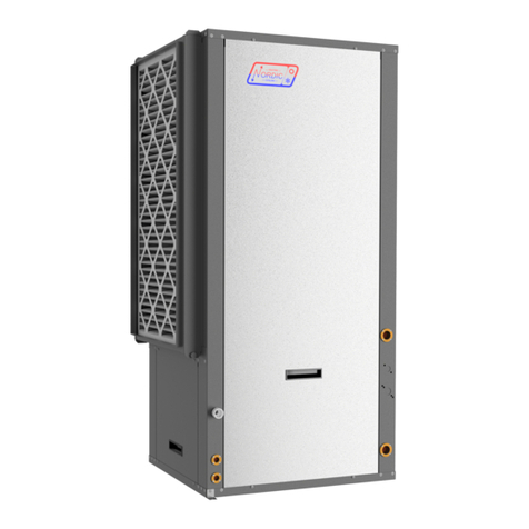
Nordic W Series Manual