02 JAN 2014 Page 001200MAN-05
THERMOSTAT REQUIREMENTS
The R-Series model requires a three-stage heating and
two stage cooling heat pump configurable thermostat for two-
stage models. The stages are S = Stage compressor, S2 =
Stage 2 compressor and S3 = electric auxiliary (heating only).
One can be purchased with the unit, or other heat pump thermo-
stats with the same number of stages can be used. The electri-
cal box diagram on the electrical box cover provides a descrip-
tion of the signal connections as in TABLE 3. Refer to DRAW-
ING 001827CDG for a diagram of the connections between the
thermostat and the heat pump.
NOTE: Some models are not available in two-stage at the pre-
sent time, models numbers with a T in the Compressor Stages
designator are two-stage, models with an S are single stage
(verify the model number against pages 2 and 3 of this manual,
or refer to the Ele tri al Tables near the end of this manual to
determine if the model is two stage or one stage). The Y2 sig-
nal is not used for these units, and they only require a 2 stage
heat stage cool thermostat. The stages are S = Compressor
and S2 = electric auxiliary (heating only). If the selected thermo-
stat has more stages than this, configure it for 2 and .
FAN MOTOR
The unit is equipped with a direct drive ECM fan motor for
maximum efficiency. The motor features a soft start which fur-
ther improves efficiency by eliminating inrush current and pro-
vides a smooth, quiet ramp up to speed . The motor will main-
tain the programmed air flow up to the maximum external static
value. Refer to the APPENDIX B: ECM Fan Airflow Tables.
The air flow can be set to four different levels by changing
the position on the Air Flow board located in the electrical box.
The four levels are indicated in TABLE 4. The actual air flow
values can be found in APPENDIX B.
Units are shipped with the MED position selected for nomi-
nal air flow. The air flow can be further reduced by 5% by
making a dry contact across AR
1
and AR
2
on the terminal strip.
This can be used for applications that have multiple zones, or
retrofits with undersized ductwork, to help reduce air flow noise
in the ductwork. It is recommended that airflow reduction only
be used with the High or Max air flow setting. Care should be
taken to ensure that the unit does not trip a safety control in
heating or cooling mode if the 5% reduction is used in conjunc-
tion with the MED or LOW air flow setting.
FAN RETURN ORIENTATION
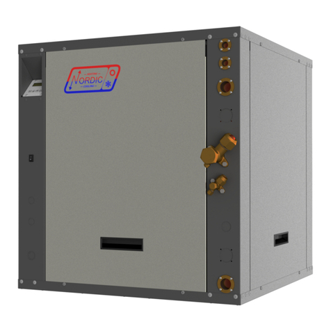
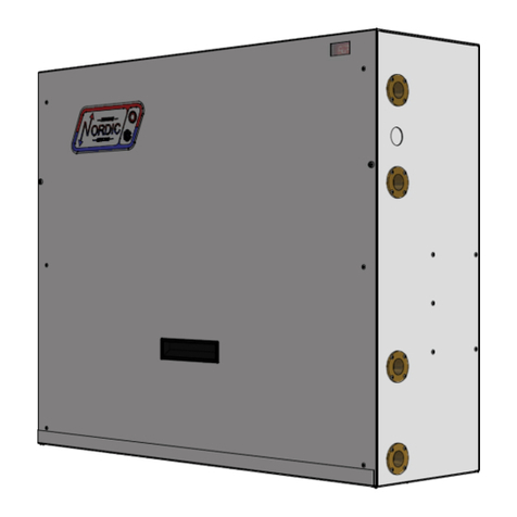
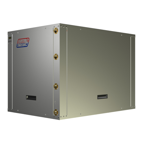
The R-Series heat pump can be ordered as a left or right
hand return from the factory. This must be specified at time of
order as the physical construction of the two configurations is
different. Refer to the CASE DETAILS section of this manual or
the specification documents for physical dimensions of the units.
FAN OUTLET ORIENTATION
The R-Series heat pumps have a field configurable fan.
It’s default location from the factory is in the top of the unit, pro-
viding a “ninety” in the airflow. It can easily be placed in the side
of the unit for straight through airflow.
To switch the location of the fan outlet follow these simple steps:
. Turn the power of to the unit.
2. Remove the screw that holds the side access panel in
place and remove the access panel by pulling up on
the handle and then outward from the bottom.
3. Disconnect the two wire harnesses and ground wire
from the fan motor.
4. Repeat step 2 for the access panel with the fan
mounted in it. Set the assembly on the floor.
5. Disconnect the plenum heater extension from the fan
housing and from the access panel.
6. Mount the fan housing directly to the access panel.
7. Install the fan/panel in the new location and secure
with the screw.
8. Reconnect both harnesses and ground wire.
9. Install the remaining access panel and secure with the
remaining screw.
SAFETY CONTROLS
The heat pump has two built in safety controls which are
designed to protect the unit from situations which could damage
it should the operation of the refrigeration circuit fall outside the
allowable operating range.
A. Low Pressure Control
The low pressure control monitors the compressor suction
pressure and will shut the compressor down if the refrigerant
evaporating pressure becomes too low, risking the danger of
freezing conditions in the evaporator.
There are (3) main reasons why this control would activate
in response to the operating conditions of the unit while operat-
ing in heating mode:
. Low or no Outdoor loop flow.
2. Low Outdoor loop entering liquid temperature.
3. Dirty or fouled Outdoor loop heat exchanger.
TABLE 4 - Airflow Selections
Position Airflow
LOW -6%
MED Nominal
HIGH +6%
MAX +12%
TABLE 3 - Control Signal Description
Signal Des ription
C 24VAC Common (Ground)
G Fan low speed (for air ir ulation)
Y
1
Heat Pump Stage 1
R
H
24VAC Hot
L Fault (24VAC when fault ondition)
W
2
Heat Pump Stage 3 (auxiliary heat) /
Emergen y Heat
O Cooling Mode (reversing valve)
Y
2
Heat Pump Stage 2 (Not used for single
stage units)
AR
1
Airflow Redu tion*
AR
2
Airflow Redu tion*
C(I) Plenum Heater dry onta t
(Conne t to C or I in plenum heater)
1 Plenum Heater dry onta t.
(Conne t to 1 and 2 in plenum heater)
* Connect AR
1
to AR
2
with a dry contact to reduce the air-
flow by 5%. Refer to the Fan Motor sub-section for more
information.

