Nordmann AT 3000 series User manual

NORDMANN
ENGINEERING
NORDMANN
ENGINEERING
Steam humidifiers of the AT 3000 series
Operating instructions
●Installation
●Connecting the water and the electrics
●Putting into operation
●Servicing and system signals
●Spare parts
●Technical specifications

2
Introduction
You have purchased a NORDMANN steam humidifier which, provided you observe the operating instructions, will
ensure fully automatic operation and reliable, low-maintenance service. Therefore, read these operating instructions
carefully and pay particular attention to the safety instructions and warnings.
Should you have any queries that go beyond the scope of these operating instructions, please contact the company
from which you purchased the humidifier. As the manufacturers, we are, of course, always ready to be of assistance,
since we want all of our customers to be completely satisfied with our products.
List of contents
1. Installation
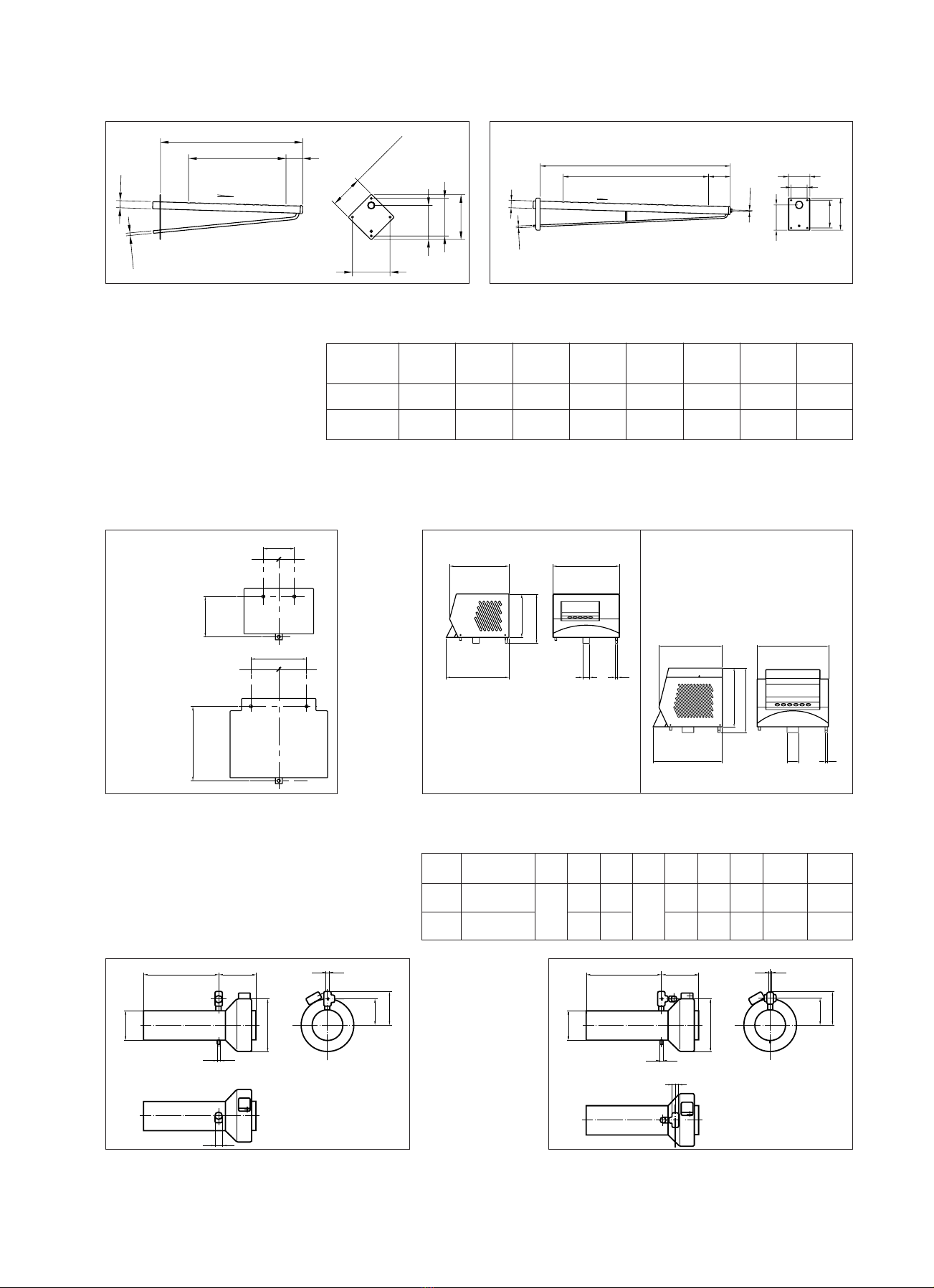
1.1 Dimensions.............................................................................................................................................................................................................
1.2 Steam nozzle.........................................................................................................................................................................................................
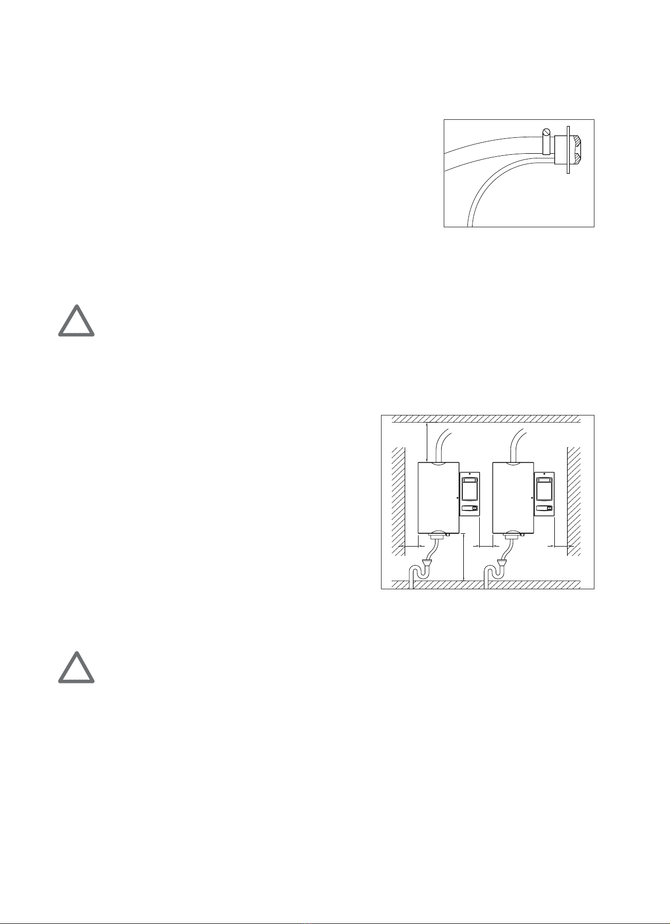
1.3 Fitting the humidifier.........................................................................................................................................................................................
1.4 Fitting the steam-distribution pipe................................................................................................................................................................
1.5 Fitting the steam blowers.................................................................................................................................................................................
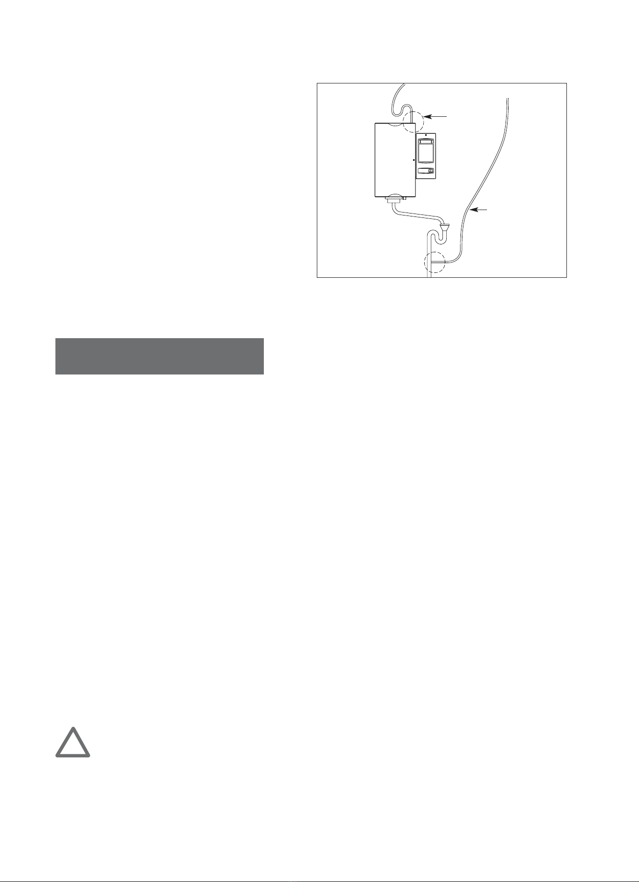
1.6 Laying the steam hose.......................................................................................................................................................................................
1.7 Laying the condensate hose.............................................................................................................................................................................
2. Water connections
2.1 Quality of the water............................................................................................................................................................................................
2.2 Water intake and drainage...............................................................................................................................................................................
3. Electrical connections
3.1 Safety instructions..............................................................................................................................................................................................
3.2 Control voltage.....................................................................................................................................................................................................
3.3 Heating voltage....................................................................................................................................................................................................
3.4 Proportional adaptor (option).........................................................................................................................................................................
3.5 RS 485 interface...................................................................................................................................................................................................
4. Putting into operation
4.1 How the humidifier works.................................................................................................................................................................................
4.2 The steam cylinder and the SC-System........................................................................................................................................................
4.3 Putting the humidifier into operation..........................................................................................................................................................
4.4 Automatic operation..........................................................................................................................................................................................
4.5 Programming level...............................................................................................................................................................................................
4.6 Safety functions...................................................................................................................................................................................................
4.7 Information from the display..........................................................................................................................................................................
4.8 Servicing and system messages.......................................................................................................................................................................
5. Servicing and maintenance
5.1 Cleaning and replacing the steam cylinder.................................................................................................................................................
5.2 Drainage strainer in the steam cylinder.......................................................................................................................................................
5.3 Removing the electronics unit........................................................................................................................................................................
5.4 Taking the humidifier out of operation.......................................................................................................................................................
5.5 Regular servicing..................................................................................................................................................................................................
5.6 Service program...................................................................................................................................................................................................
5.7 Integrated humidity controller ..................................................................................................................................................................
6. Rectifying faults
6.1 The humidifier produces insufficient or no steam...................................................................................................................................
7. Spare parts list...........................................................................................................................................................................................................................
8. List of options.............................................................................................................................................................................................................................
9. Technical specifications...........................................................................................................................................................................................................
3
6
6
6
8
9
10
10
10
11
11
11
12
12
12
13
14
14
14
14
15
16
16
17
17
17
18
18
20
21
22
22
23

3
Safety instructions
Please read and observe the operating instructions before fitting and putting into operation.
Very important!
The operating instructions should always be readily available and kept in the immediate vicinity of the humidifier.
All work must be done only by persons who are familiar with the product and are sufficiently qualified to perform the
work.
The AT 3000 steam humidifiers have been designed and constructed in accordance with the latest technology and the
accepted safety regulations. However, if misused, the humidifier can present a danger to both the user and third parties.
Apart from these safety instructions, you should observe all national and local regulations.
Proper use
The AT 3000 steam humidifiers are intended solely for indirect (via a steam-distribution pipe in a ventilation duct) or
direct (with either a separate or a humidifier-mounted fan) humidification. Used in any other way, or in a way that goes
above and beyond the one described above, is contrary to its intended usage. The manufacturer/supplier cannot be
held responsible for any damage resulting therefrom. The user shall bear the risk.
Alterations to the humidifier
Without NORDMANN’s written approval, no alterations may be made to the humidifier itself, the components or the
accessories.
The use of non-original spare parts may lead to our refusal to accept responsibility for any damage arising therefrom.
Safety instructions
Whenever you see either of these signs, particular care must be taken.
1. Installation
1.1 Dimensions
Dimensions of the AT 3000 humidifiers
!
Type Fig. mm mm mm Steam outlet Drainage
A B C
41 390 585 230 1 x Ø 22 1 x Ø 22
81 390 585 230 1 x Ø 22 1 x Ø 22
15 1 470 645 305 1 x Ø 35 1 x Ø 22
23 1 470 645 305 1 x Ø 35 1 x Ø 22
32 1 525 715 360 1 x Ø 35 1 x Ø 22
45 &65 1 525 715 360 2 x Ø 35 1 x Ø 22
64 2 975 730 385 2 x Ø 35 2 x Ø 22
90 &130 2 975 730 385 4 x Ø 35 2 x Ø 22

4
Fixing holes for type 64, 90 &130 kg/h (mm) Fixing holes for type 4-65 kg/h
Dimensions of the steam-distribution pipes
A
B
Fig. 1
550
300 300
930
Fig. 3 Fig. 4
4 holes required
for humidifiers of
15 kg and above
3 holes required
for humidifiers of
4 and 8 kg/h
Type A B
(mm) (mm)
4 - 8 kg 100 350
15-23 kg 180 410
32-65 kg 220 450
Tiefe Breite
Höhe
Fig. 2
CA
B
CA
B
Type/mm A B C D Fig. Art no.
22-300 300 Ø 22 176 60 5 902 00 00
22-450 450 Ø 22 300 70 5 902 00 01
22-650 650 Ø 22 504 70 5 902 00 02
22-850 850 Ø 22 696 70 5 902 00 03
35-300 300 Ø 35 200 55 5 902 00 04
35-450 450 Ø 35 300 80 5 902 00 05
35-600 600 Ø 35 425 90 5 902 00 06
35-900 900 Ø 35 680 110 6 902 00 07
35-1200 1200 Ø 35 935 110 6 902 00 08
35-1500 1500 Ø 35 1275 110 6 902 00 09

5
A
DC
B
ø8
3%
138
116
105
116
100x100
Fig. 5
3%
A
CD
M6
B
ø8
118
150
130
100
75
Fig. 6
Dimensions of the
4-23 kg/h steam blowers
A
B
==
B
A
==
Fig. 7 Fig. 8 Fig. 9
BA
D
E
CGF
AB
D
C
E
FG
Type A B
4 - 8 kg 100 130
15-23 kg 180 240
Fixing holes for 4-23 kg/h
steam blowers
Dimensions of the 4-23 kg/h steam blowers
Type 4-8 kg/h Type 15-23 kg/h
Dimensions of the Turbo 32, 45 &65 kg/h
steam blowers
Fig. 10 Fig. 11
BC
AD
E
G
F
H
J
BC
AD
E
G
F
H
J
Fig. Type A B C D E F G
mm mm mm mm mm mm mm
8 4 - 8 kg/h 230 205 220 145 165 Ø 22 Ø 8
9 15-23 kg/h 310 275 295 255 285 Ø 35 Ø 8
Fig. Type A B C D E F G H I
10 32 kg/h Ø 505 255 Ø M10 185 235 Ø 35 Ø 8
11 45 &65 kg/h 200 505 255 350 M10 185 235 Ø 2 x 35 Ø 8

6
1.2 Steam nozzle
For smaller outputs of up to 4 kg/h, we offer a steam nozzle which can be
either fitted in air ducts, for instance, or used for direct room humidification.
The rules for the humidification distance (distance needed to mix the
steam adequately with air) must be observed here, too.
When the steam nozzle is employed, the length of the steam hose should not
exceed 1.5 metres.
1.3 Fitting the humidifier
All installation work must be performed by trained personnel. The customer himself is responsible for verifying
their qualifications.
When fitting the humidifier, use only the material supplied with the unit and observe the various minimum distances
that have been stipulated.
To open the humidifier, turn the screw, using the correct screwdriver, in an anti-clockwise direction; the door to the
water componentry or the electrics then opens. To close, simply push back into place (no screwing down is necessary).
Positioning the humidifier
Ensure that there is sufficient room to perform servicing
and maintenance work, and that the unit is easily accessible.
To facilitate such work, mount the unit at eye level.
We recommend that you fit the humidifier as near as possible to
the steam-distribution pipes. The highest degree of efficiency is
attained when the humidifier is linked to the steam-distribution
pipe by the shortest possible steam hose.
When installing the double units (types 64, 90 and 130 kg/h) next
to each other, ensure that each drainage pipe is fed to a funnel
of adequate size.
1.4 Fitting the steam-distribution pipe
All installation work must be performed by trained personnel. The customer himself is responsible for verifying
their qualifications.
The visible jet of steam issuing from the steam-distribution pipe dissipates in the air only after a certain distance.
In order to prevent condensation, a certain minimum distance to other parts of the installation (such as ventilators,
filters or pipe bends) must, therefore, be maintained.
The steam-distribution pipes can be fitted either vertically or horizontally, though you must ensure that the steam
outlets are always vertical to the air flow. If fitted horizontally, these apertures must be at the top.
An adhesive template is supplied with each steam-distribution pipe to facilitate installation in, for instance, an air duct.
NORDMANN’s steam-distribution pipes are designed so that, if fitted straight, there is automatically a slight decline
of 3% which ensures that any condensate flows back again.
The ends (reverse side of mounting plate) of the longer steam-distribution pipes (types 35-900, 35-1200 and 35-1500)
are equipped with an M6 fixing bolt.
Fig. 12
320
380
100 100 100
Fig. 13
!
!

7
2/31/3
min 300
Fig. 14
A
==
A
B
Fig. 16 A = min. 250
B = min. 150
Fig. 15 A = min. 200
Guidelines on fitting the steam-distribution pipes
Various fitting methods
A
B
C
D
A
B
==
A
B
A
B
CCC
A
BB
B
==
Fig. 19 A > 500
B = min. 100
Fig. 20 A > 500
B = min. 150
C = min. 0.15 A
Fig. 17 A > 300
B = 0.5 A
Fig. 18 A > 350
B = min. 150
C = 0.3 A
D = min. 100
Fig. 21 A = min. 175
B = min. 100
Fig. 22
Pressure-
compensation
hose
Stench trap
Type: Sperrfix 3
Tight-fitting
rubber bung
Steam-distribution pipe fitted on suction side
Because of the under-pressure in the
appliance or duct part, condensate
may be trapped in the steam-
distribution pipe. If there is an outlet
in the empty part (intended for the
distribution pipes) of the humidifier,
the condensate can be bled off in
the immediate vicinity. An alternative
method of bleeding off the
condensate can be seen in the
diagram.

8
1.5 Fitting the steam blowers
All installation work must be performed by trained personnel.
The customer himself is responsible for verifying their qualifications.
The steam blower for distributing the steam in the room can be fitted either directly onto the humidifier itself
(excepting types 32 to 130 kg/h) or onto a wall.
For the humidifier to work best, correct steam distribution is essential. For this reason, you must observe the minimum
distances when installing the equipment.
Minimum distances for steam blowers of type 4-23 kg/h
Minimum distances for steam blowers of type 32-65 kg/h
B
A
Fig. 23
Fig. 25Fig. 24
450 mm
450 mm
min.
15 m
.
15 m
Type 32: min. 1500 mm
Type 45: min. 2000 mm
Technical specifications for steam blowers
!
Type
A B
min. min.
4 kg 600 mm 3 m
8 kg 900 mm 5 m
15 kg 1000 mm 7 m
23 kg 1000 mm 10 m
Max. steam Air flow Power Nominal Weight Steam pipe Condensate Noise
output m3/h supply power kg H pipe G level (1m)
4 kg/h-8 kg/h 110 200/240 V 25 W 5 Ø 22 mm Ø 8 mm 46 dB (A)
15 kg/h-23 kg/h 650 50/60 Hz 170 W 15 Ø 35 mm Ø 8 mm 54 dB (A)
32 kg/h 800 220/240 V 110 W 8 Ø 35 mm Ø 8 mm 72 dB (A)
45 &65 kg/h 800 50/60 Hz 110 W 8 2 x Ø 35 mm Ø 8 mm 72 dB (A)
Type 32: min. 1500 mm
Type 45&65: min. 2000 mm

9
1.6 Laying the steam hose
The steam hose should be kept as short as possible. It should not be possible to block or obstruct the steam supply lines
in any way. Furthermore, they must be protected from outside interference (e.g. deformities, kinking etc.). After
the hose has been laid, it is advisable to re-check everything when the hose is warm. It is equally important to avoid
condensation pockets in the hose. Any curves should have as large a radius as possible.
Installation material
If a hose is used for the steam line, it must be the original one supplied by NORDMANN. If other hoses are utilised,
NORDMANN cannot be held responsible for any damage that may occur. A hose clamp should be used to link the hose
to the steam-distribution pipe.
When laying the steam hose in pipes, cable ducts etc., you must verify their resistance to high temperature (min. 100 ºC).
All insulation material must also be checked for its resistance to high temperature.
If the steam line installed is of copper, small radii should be avoided wherever possible. Every bend causes an additional
resistance. A steam line of copper must have the same diameter as the hose.
If the steam lines are long with a lot of bends and a relatively high internal duct pressure, water may be continuously
forced out of the steam cylinder, which impairs performance.
Correctly installed
300
min 20%
Fig. 26
300
300
5%
Fig. 27 Fig. 28 Fig. 29
Possible Wrongly installed Possible
300

10
1.7 Laying the condensate hose
It is advisable to lay the condensate hose as near to
the vertical as possible and to feed the condensate
either directly into an open funnel or below the
siphon.
If the steam-distribution pipe is fitted above the
humidifier, the condensate can be fed back to the unit
by placing the end of the hose in the filling cup.
In this instance, a small siphon should be formed with
the condensate hose.
If the condensate is drained off directly, it is advisable
to feed back the condensate hose separately. The
end of the condensate hose should be in the open air.
If the end of the hose is submerged in water,
the condensate is prevented from draining away. Fig. 30
Condensate
fed back
to the unit
Condensate
drained off
separately
2. Water connections
2.1 Quality of the water
NORDMANN humidifiers use ordinary tap water for the production of pure steam. The electrical conductivity should
be between 125 and 1250 microsiemens per cm. The hardness of water is measured in accordance with the international
unit millimol, calcium and magnesium ions per litre (mmol/l), previously the degree of German hardness (DH):
Soft water up to 1.3 mmol/l; up to 7 °DH
Fairly hard water 1.3 to 2.5 mmol/l; 7 to 14 °DH
Hard water 2.5 to 3.8 mmol/l; 14 to 21°DH
Very hard water over 3.8 mmol/l; over 21°DH
Other international units: 1°DH = 1.79 ° French hardness
1°DH = 1.25 ° English hardness
1°DH = 1.05 ° American hardness
1°DH = 10 mg/l CaO
1°DH = 17.9 mg/l CaCO3(ppm)
NORDMANN’s electrode steam humidifiers allow you to use water ranging from soft to very hard, without the need
for prior treatment. However, for fairly hard water and above, we recommend the use of the SC-System (NORDMANN’s
self-cleaning system), since this greatly reduces the amount of maintenance required for the cylinder.
2.2 Water intake and drainage
All installation work must be performed by trained personnel. The customer himself is responsible for verifying
their qualifications.
Please observe local regulations concerning the connection of appliances to the pressure and drainage systems.
The humidifiers are designed to operate on ordinary tap water. If you intend using treated or de-mineralised water,
consult your NORDMANN representative beforehand.
!

11
Connecting to the cold-water supply, with stop cock
Where the water pressure is between 1 and 10 bar
(0.1 to 1 MPa), the unit can be connected directly to
the water supply. If it is over 10 bar (1 MPa),
connection must be via a pressure-reduction valve
(set to 4–6 bar = 0.4–0.6 MPa).
In any case, the water feed pipes that you have laid
must be flushed thoroughly before connecting them
to the humidifier. You should use copper piping only.
Note that the drainage facility should provide the
possibility of performing cleaning and maintenance.
The drainage pipe should have a decline to the
drainage system of at least 5%.
A fine filter should be fitted at the water intake to
the humidifier; this prevents the rapid build-up
of impediments in the inlet filter of the inlet valve.
3. Electrical connections
3.1 Safety instructions
All work pertaining to the electrical installation must be carried out by qualified personnel only. The customer is
responsible for verifying the qualifications of the technicians concerned.
Before performing any electrical work, all power to the humidifier must be disconnected. Please observe local
regulations concerning electrical installations. The installation must be fitted with a device which disconnects the unit
(with a contact opening of at least 3 mm) on all phases from the mains power supply. NORDMANN humidifiers
are designed to be connected to the earth lead and are categorised as belonging to Protection class 1 for electrical
equipment. The connection details are provided in the wiring diagrams for each type of unit. Each unit is supplied
with the appropriate wiring diagram.
!
Fig. 31
Tap (supplied
by customer)
Drainage cup
horizontal
or vertical
Fine filter
(supplied by
customer)
3/4“
3/8“
3.2 Control voltage
The standard control voltage of 220–240 V must be applied to terminals L1 and N. A 6.3A spare fuse (F1),
located in the terminals of the fuse holder, is incorporated in the humidifier. The electronics and the accessories have a
24 V power supply which is protected by a fuse (F2). A spare fuse is situated in the terminals of the fuse holder.
N.B.: When performing cleaning and maintenance work on the unit, all power to the humidifier, including the
control voltage, must be disconnected.
3.3 Heating voltage
The cross-section of the electrical wires and the minimum fuse size should be chosen in accordance with the
connection requirements (cf. technical specifications) of the type of humidifier employed. The electric supply cables
must be connected to the unit’s terminals correctly. We recommend to re-tighten the screw terminals after a few days.

12
3.4 Proportional adaptor (option)
The proportional adaptor can be either factory fitted or fitted subsequently by the customer simply by inserting it onto
the electronics unit.
The following control signals from humidity controllers can be processed:
0-2 V 0-5 V 0-10 V 0-16 V
0-20 V (SCS) 1-5 V 2-10 V 0-20 mA
4-20 mA potentiometer min. 135 Ohm
3.5 RS 485 interface
The standard RS 485 interface provides a data transmission system in accordance with the American EIA (Electronic
Industries’ Association) standard, permitting high-speed transmissions free of disturbance. Data are transmitted in series
via two wires. To supply the accessories with power, there is a 24 V d.c. system with two other wires.
The bus structure enables both closed and open lines with stub cables and branches (tree system).
Transmission is performed on a twisted and screened two-wire cable, at distances of up to 1.2 km without amplifiers,
and with up to 32 subscribers.
4. Putting into operation
4.1 How the humidifier works
NORDMANN humidifiers use ordinary tap water to
produce steam. The water is converted directly
into steam in a steam cylinder by electrode heating
using electrical energy. In so doing, the water
acts as the electrical resistance. Vaporisation occurs
at atmospheric pressure (non-pressurised).
The electronic control system, with its highly-integrated microcontroller, regulates the vaporisation process in
accordance with a new principle developed by NORDMANN which allows rapid output changes to be made.
The humidifier adapts itself fully automatically to the quality of the water used. Due to this ability to set the optimum
water concentration in the steam cylinder, the smallest of adjustments to the water level can effect a change
in the steam output. Therefore, the unit reacts quickly and accurately to any setpoint changes. Because of its ultimate
degree of efficiency, this new type of control system ensures perfect drainage, i.e. the process of water decon-
centration in the cylinder. The use of fuzzy logic technology improves the controllability. The microcontroller of the
AT 3000 series works with fuzzy-logic algorithms. This regulates the conductivity or mineral concentration in the
steam cylinder and achieves ideal operating conditions while, at the same time, maximising the operational reliability.
Furthermore, the output fluctuations which occur during normal operation are kept to a manageable minimum
by the automatic water-intake and drainage functions.
S
EE
Fig. 32
Hydrodynamic
filling cup
S = maximum-level sensor
E = electrode

13
4.2 The steam cylinder and the SC-System
The SC-System is a patented self-cleaning system developed by NORDMANN for its electrode steam humidifiers.
Because the minerals are kept in suspension, there is little accumulation of deposits on the floor of the cylinder. The
loose minerals are flushed away during normal drainage operations. The steam cylinder’s service life is considerably
lengthened and the time spent on maintenance is reduced.
The serviceable life of a steam cylinder is dependent on both the quality of the water supply and the unit’s actual
operating hours.
Lifetime of a steam cylinder at 100% steam output
A regular check of the steam cylinder ensures trouble-free operation.
If the humidifier indicates U1 (cf. 4.8), it can still be run for a few days before the steam cylinder needs to be replaced.
We recommend that you keep a spare cylinder in stock for each unit.
NORDMANN’s steam cylinders are so economical that it is usually cheaper to replace the cylinder than to clean it.
To clean the cylinder, it should first be emptied (by pressing the button for manual draining) and then removed.
After the drainage filter has been taken out, the cylinder can be well flushed with tap water (using no chemical
substances).
10
20
30
1000500 1500 2000
t (h)
°d Härte
Fig. 33
1°DH = 1,79° French hardness
1°DH = 1,25° English hardness
1°DH = 1,05° American hardness
1°DH = 17.9 mg/I CaCo3(ppm)
Hours
with SC-System
without* SC-System
ºDH (German hardness)
*but cylinder is flushed periodically

14
4.3 Putting the humidifier into operation
After the steam hose, water feed pipe, drainage pipes and electrical cables have all been correctly connected, the
AT 3000 humidifier can be switched on using the black power switch. When the T4 key is pressed, the LED for output
limitation lights up and the level of output limitation is shown on the display. All humidifiers are set ex works
to 100% output. If the SELECT key is pressed, you can choose a different level of output limitation.
As soon as the humidistat or humidity controller demands humidification, the green Humidification LED lights up,
the contactor is activated and, soon after, water is fed into the steam cylinder, whereupon fully automatic operation
commences.
Of course, the humidifier will operate automatically only if (a) it was installed by a specialist and (b) the shut-off valve
in the water feed pipe is open.
After the water in the steam cylinder has been heated up, the production of steam begins.
During the start-up phase, or after a new replacement cylinder has been fitted, the maximum water level, or Niveau
max. can be attained. When Niveau max. has been reached, the inlet valve closes briefly; this is a normal occurrence
during the steam cylinder’s concentration phase. The length of this phase can differ; it lasts until the cylinder has
reached the nominal rating. In the first stage of the service level, you can check whether Niveau max. has been attained
(see Item 5.6).
4.4 Automatic operation
The AT 3000 series’ special electronic controls unit with microcontroller regulates all operations automatically, so that
the user does not need to take any action or make any settings during normal running.
4.5 Programming level
The humidifiers of the AT 3000 series have a programming level which has a large array of functions, allowing
the unit’s characteristics to be matched to a wide variety of conditions or tailored exactly to the customer’s particular
requirements.
You are not permitted to use the programming level unless authorisation to do so has been granted by a NORDMANN
specialist. Your NORDMANN representative will be glad to advise you in this matter.
4.6 Safety functions
NORDMANN humidifiers are protected against running dry, i.e. the power is cut off automatically as soon as the
electrodes in the steam cylinder protrude above the water level.
If current consumption becomes excessive (25% above the normal level), the outlet valve is opened automatically.
Because the electrodes are then in contact with less water, current consumption falls back to the nominal value.
If current consumption fails to fall below 140% of the nominal level even after several drainage operations, the
humidifier soon turns itself off automatically, and «U2» appears in the display.

15
4.7 Information from the display
The large-scale, four-digit, LED display allows numbers and letters to be indicated. Its size and clarity mean that it can
be read easily even when the light is poor.
Key Function
T1 Allows the steam cylinder to be manually drained. Pressing T1 once
causes the drainage valve to open. The red LED flashes. Pressing it again
causes the valve to close. If you forget to close the valve, it closes
automatically after 30 minutes.
T2 Works on double units only. Pressing T2 allows you to read or set the
operating data of either the left- or right-hand steam cylinder (the red
LED indicates which one).
T3 Allows you to select and show 3 operating variables: steam output
[kg/h]; current [A]; setpoint steam [%]. When T3 is pressed, the relevant
LED indicates which variable is being shown on the display.
T4 Allows you to select:
• humidifier capacity limitation in %
• access to the programming level
• access to the servicing level
The relevant LED shows which option you have selected.
1. Humidifier capacity limitation in %.
On pressing T4 for the first time, the capacity limitation LED lights up.
The limitation value appears in the display and can be set, using the
SELECT button, between 20 and 100% (factory setting is 100%). When
another key is pressed, the last limitation value is automatically saved.
2. Activating the programming level.
When T4 is pressed again, you reach the programming level. The LED of
the T5 (SELECT) key then flashes, inviting you to select a defined
function (cf. Item 4.5). Use the SET key to activate functions or make
settings.
3. Activating the servicing level.
Pressing T4 yet again enables you to reach the servicing level. The
LED of the T5 (SELECT) key then flashes, inviting you to check defined
elements (cf. Item 5.6). Use the SET key to obtain information or
perform the component check.
T5 The SELECT key allows you to:
• select stored functions in the programming level
• select defined checking stages in the servicing level
• set the output limitation
T6 The SET key allows you to:
• activate, de-activate or parameter the special functions in the
programming level
• switch particular elements on or off in the servicing level
Reset Key T6 (SET) also serves as a RESET button when «U codes» appear
in the display.
T1T2T3
T4T5T6
Fig. 34

16
4.8 Servicing and system messages
The newly-developed electronic controls unit with microcontroller continuously monitors the operations of the AT 3000
humidifiers. Any deviations from the operating condition (U codes) are shown on the display.
Code U1 Servicing signal
The steam cylinder can no longer attain the nominal output and needs, therefore, to be cleaned or perhaps replaced.
A visual inspection of the inside of the cylinder is necessary to be able to decide whether it needs replacing. Code U1 is
purely a servicing code; the unit does not switch off automatically. The humidifier continues to function at a reduced
output. Acknowledgement is effected by pressing T6 SET button (cf. Item 4.7).
Code U2 Excess current
Whenever there is excess current (140% of the nominal value) during normal operations, the humidifier switches
itself off automatically for safety reasons. After the fault has been rectified, the humidifier is put back into operation
by pressing T6 SET button (cf. Item 4.7).
Code U3 The humidifier fills continuously
Either there is no heating phase or no water in the cylinder due to the water supply having been cut off. The humidifier
switches itself off automatically after 30 minutes and is put back into operation by pressing T6 SET button (cf. Item 4.7).
Code U4 Microcontroller uncoded
This signal appears if a replacement electronic controls unit has been fitted to the humidifier without being coded.
The humidifier is prevented from operating. The signal disappears as soon as the electronic controls unit has been coded.
Code U5 Preset number of operating hours attained
This signal can appear only if the number of operating hours for the steam cylinder has been pre-programmed. This
is of benefit, for example, if regular servicing periods have been prescribed in accordance with hours run. U5 is purely a
servicing code; acknowledgement is effected by pressing T6 SET button (cf. Item 4.7).
The standard, potential-free relay output enables either collective alarms or just one «U» signal (which can be chosen in
the programming level) to be displayed remotely.
5. Servicing and maintenance
5.1 Cleaning and replacing the steam cylinder
Before commencing, switch off all power to the humidifier and disconnect the unit from the mains.
The serviceable life of the steam cylinder depends on both the hours run and the hardness of the tap water used.
The cylinder should be replaced when the electrodes have become insulated so much (because of calcification) that the
required steam output cannot be reached. At the same time, the water level in the cylinder continuously touches
the Niveau max. sensor. In this case, the specially-constructed water filling cup offers additional protection by feeding
excess water directly into the overflow facility, allowing it simply to drain away.
Whenever U1 appears in the display, you should proceed as described on this page. However, the humidifier can still be
run for some time before you need to replace the steam cylinder.
!

17
Procedure for replacing the steam cylinder
• Open the drainage valve using the manual drainage switch (key T1); the cylinder then empties itself completely.
Let the cylinder cool down.
• Before proceeding further, disconnect the unit from the mains.
• Loosen the clamp on the steam hose, pull off the hose and remove the electrical plug from the cylinder; the cylinder
itself can now be removed.
• To fit the new unit, reverse the above procedure. It is advisable to wet slightly either the O-ring seal on the drainer or
the outside of the cylinder’s drainage aperture, since this makes it easier to fit the new cylinder.
The humidifier is re-started in accordance with the recommendations detailed in the chapter entitled «Putting the
humidifier into operation».
5.2 Drainage strainer in the steam cylinder
All NORDMANN steam cylinders are fitted with a removable drainage strainer which can be extracted easily for
cleaning.
The drainage strainer and the cylinder can then be put back into place and the humidifier put back into operation.
5.3 Removing the electronics unit
All work pertaining to the electrical installation must be carried out by qualified personnel only. The customer is
responsible for verifying the qualifications of the technicians concerned.
Before removing the electronics unit, all power to the humidifier must be switched off.
The electronics unit comprises a processor pcb (printed circuit board) and a display pcb. All pcbs have plug-in
connections, which facilitates their replacement. After a replacement of the processor pcb make sure that the print is
coded according to the type of unit.
5.4 Taking the humidifier out of operation
Should you wish to take the humidifier out of operation for a long period of time (e.g. in summer or when the air-
conditioning system is not operated), the steam cylinder must be emptied.
Before proceeding, switch off all power to the humidifier.
Fig. 35
black
red
white
black
red
white
!
!
!

18
5.5 Regular servicing
Regular servicing helps to maintain the operability and reliability of the humidifier.
All work must be carried out by qualified personnel only. The customer is responsible for verifying the qualifications
of the technicians concerned.
Before commencing work, all power to the humidifier must be switched off.
The following checks should be carried out on a regular basis:
•Inspect and clean the steam cylinder.
If there are any deposits in the steam cylinder, you should remove the drainage strainer and flush the cylinder
thoroughly with tap water (using no chemical substances). If the electrodes are worn, it is time to replace the steam
cylinder.
•Inspect the steam, condensate and water hoses.
Check that they are still correctly laid and that the hose clamps are still tight. Check that the hoses are still in good
condition.
•Inspect and clean the inlet and outlet valves.
If worn, or covered in scale deposits, replace the valves.
•Check the drainage cup and, if necessary, clean or replace it.
5.6 Service program
The service program of the AT 3000 humidifiers provides you with information on operating conditions and allows you
to set the defaults for the integrated humidity controller (from software version XP16B or higher). Furthermore it
enables you to check the components of the unit. You are advised to check the components on regular basis.
After you have left the service program, the humidifier works in accordance with the operating conditions that were set
originally.
Checking and setting operations:
SE: Check the Niveau max. sensor
H: Check the humidistat or presence of controller signal
Hc: Activate the integrated humidity controller (cf.item 5.7)
rH: * Set the humidity set point of the integrated hum.controller (cf.item 5.7)
Pb: * Set the proportional band of the integraged hum.controller (cf.item 5.7)
- -: If you continue, steam production will be interrupted
h: Simulation of the humidification signal
I: Inlet valve
O: Outlet valve
C: Contactor
SC: Self-cleaning system
r1: Relay for remote collective alarm
r2: Option: second relay for remote indication
r3: Option: third relay for remote indication
End: End of service program
* only visible when Hc is activated (Hc 1 or Hc 2)
If you choose SE, H, Hc, rH, and Pb the humidifier continues to produce steam; for
all other functions (after - -), steam production is interrupted.
T1T2T3
T4T5T6
Fig. 36
!

19
Starting the service program
•Key T4 Select the servicing level
•Key T5 (SELECT) To select the checking operations
•Key T6 (SET) To select either 1 (active) or 0 (inactive), or to switch components on or off
N.B.: On double units (two cylinders), first choose the appropriate cylinder by pressing key 2.
Display indications
SE 1: Niveau max. in the steam cylinder has been reached
SE 0: Niveau max. in the steam cylinder has not been reached
H1: Humidification signal present
H0: No humidification signal present
Hc oF: *integrated controller switched off, control via external controller
Hc 1: *integrated controller activated for single units or parallel operation of double units
Hc 2: *integrated controller activated for sequencial operation of double units
rH xx: *Setting of the humidity set point 30...99%
Pb xx: *Setting of the proportional band 5…15%
- - : If you continue, steam production will be interrupted
* cf.item 5.7.2
Checking the components
h0 Humidistat/controller is switched off manually (simulation)
h1 Humidistat/controller is switched on manually (simulation)
I0 Inlet valve is closed
I1 Inlet valve is opened manually
O0 Outlet valve is closed
O1 Outlet valve is opened manually
C0 Contactor is off
C1 Contactor is switched on manually
SC 0 Pump for SC system is off
SC 1 Pump for SC system is starting up
r1 0 Relay is not energised
r1 1 Relay cuts in
r2 0 Relay is not energised
r2 1 Relay cuts in
r3 0 Relay is not energised
r3 1 Relay cuts in
End: End of service programme
Closing the service program
By pressing any key except SELECT and SET anywhere in the service program. The system returns to the same status
as it was in before the service program was activated.
☞
☞
☞

20
5.7 Integrated Humidity Controller
5.7.1 Function
The integrated humidity controller is a new feature for all AT 3000 units with software version XP 16B or higher. This
newly designed and programmable function enables the humidity in the duct or in the ambient to be controlled. For
connecting a humidity sensor to the integrated humidity controller the proportional adaptor (Art. 912 10 00) is
required.
The controller function is activated in the service level of the AT 3000 unit, afterwards the set point humidity and the
proportional band are set in the following menu points of the service level. The microprocessor electronics of the AT
3000 then controls the steam capacity of the AT 3000 as P-controller.
5.7.2 Settings
press «T4» until LED lights up at "Service Level"
press «T5 SELECT» until display shows Hc (Humidity control)
chose with «T6 SET» the desired operating mode (oF,1or 2)
change to rH with «T5 SELECT» and enter set point humidity with «T6 SET» (30...99%)
change to Pb with «T5 SELECT» and enter proportional band with «T6 SET» (5...15%)
After the integrated humidity controller is activated the display shows the measured actual relative humidity
(instead of the two horizontal hyphens).
5.7.3 Humidity Sensor
The integrated humidity controller of the AT 3000 operates with active humidity sensors which are connected to our
proportional adaptor. All common and codable sensor signals can be processed. A control voltage of 24V DC for the
sensor is available from the humidifier, should the sensor need any other supply voltage, this needs to be taken from
another source. For the wiring of the sensor please refer to diagram 344 24 38.
☞
☞
☞
☞
☞
Hc oF Integrated humidity controller switched off, control via external controller
Hc I Controller activated (for single units or parallel operation of double units)
Hc 2 Controller activated for sequential operation of double units
Table of contents
Other Nordmann Humidifier manuals
Popular Humidifier manuals by other brands

Cooper & Hunter
Cooper & Hunter CH-2828 instruction manual

Aircare
Aircare ESSENTIALS MESA Setup and owners manual

Perfect Aire
Perfect Aire 2PAU20 manual

Easy@Home
Easy@Home EE-3186A user guide

Aircare
Aircare NOVA NU319DBLK-EC Setup guide and owners manual

nor-tec
nor-tec NH Series Installation and operation manual