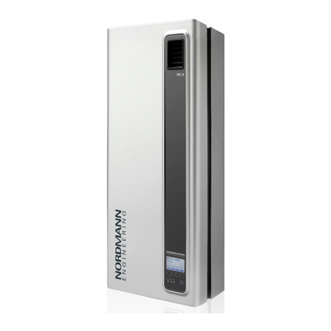
Nordmann RC4 User manual

2549079 EN 1011
Nordmann RC4/DC4
MOUNTING INSTRUCTIONS
Electrode Humidifiers
NORDMANN
ENGINEERING
NORDMANN
ENGINEERING
Dampfluftbefeuchter econoVap


3
Contents
1 Introduction 4
1.1 To the very beginning 4
1.2 Notes on the mounting instructions 4
2 For your safety 6
3 Product Overview 8
3.1 Models overview 8
3.2 Identicationoftheunit 8
3.3 Steamhumidierconstruction 9
3.4 Functionaldescription 11
3.5 Humidicationsystemoverview 12
3.6 Options 14
3.7 Accessories 14
3.7.1 Accessories overview 14
3.7.2 Accessorydetails 15
3.8 Standarddelivery 16
3.9 Storing/Transportation/Packaging 16
4 Notes for the planning engineer 17
4.1 Selecting the unit version 17
4.1.1 Selecting the unit 17
4.1.2 Calculatingthemaximumrequiredsteamcapacity 18
4.2 Selectingtheoptionsanaccessories 18
4.3 Selecting the control system 19
5 Mounting and installation work 21
5.1 Importantnotesformountingandinstallationwork 21
5.2 Mounting the unit 22
5.2.1 Notesonlocatingandmountingtheunit 22
5.2.2 Mountingthehumidier 24
5.2.3 Inspectingtheinstalledunit 25
5.3 Steaminstallation 26
5.3.1 Overviewsteaminstallation 26
5.3.2 Positioningandmountingofthesteamdistributionpipe 27
5.3.3 Installingthesteamdistributors 29
5.3.4 Installingthesteamhose 30
5.3.5 Installingthecondensatehose 31
5.3.6 Inspectingthesteaminstallation 32
5.4 Waterinstallation 33
5.4.1 Overviewwaterinstallation 33
5.4.2 Notesonwaterinstallation 33
5.4.3 Inspectingthewaterinstallation 34
5.5 Electricinstallation 35
5.5.1 WiringdiagramNordmannRC4/DC4 35
5.5.2 Notesonelectricinstallation 36
5.5.3 InsertingtheCFcard 38
5.5.4 Inspectingtheelectricalinstallation 38
6 Productspecications 39
6.1 Technicaldata 39
6.2 Unit dimensions 40
6.3 Declarationofconformity 41
4
Limitation
ThesubjectofthesemountinginstructionsisthesteamhumidierNordmannRC4/DC4 in
its different versions. The various accessories are only describedinsofar as this is necessary
forproperoperationoftheequipment.Furtherinformationonaccessoriescanbeobtainedinthe
respectiveinstructions.
These mounting instructions is restricted to the installation ofthesteamhumidierNordmannRC4/
DC4andismeantforwelltrainedpersonnelbeingsufcientlyqualiedfortheirrespective
work.
Themountinginstructionsaresupplementedbyvariousseparateitemsofdocumentation(operating
instructions,sparepartslist,manualsforaccessories,etc.).Wherenecessary,appropriatecross-
referencesaremadetothesepublicationsinthemountinginstructions.
1 Introduction
WethankyouforhavingpurchasedthesteamhumidierNordmannRC4/DC4.
ThesteamhumidierNordmannRC4/DC4incorporatesthelatesttechnicaladvancesandmeetsall
recognizedsafetystandards.Nevertheless,improperuseoftheNordmannRC4/DC4mayresultin
dangertotheuserorthirdpartiesand/orimpairmentofmaterialassets.
Toensureasafe,proper,andeconomicaloperationofthesteamhumidierNordmannRC4/DC4,
please observe and comply with all information and safety instructions contained in the present
manualaswellastheinstructionsgiveninthemanualsforthecomponentsusedinthehumidica-
tion system.
Ifyouhavequestions,whicharenotorinsufcientlyansweredinthisdocumentation,pleasecontact
yourNordmannsupplier.Theywillbegladtoassistyou.
1.2 Notes on the mounting instructions
1.1 To the very beginning

5
Symbols used in this manual
CAUTION!
Thecatchword“CAUTION”designatesnotesinthisdocumentationthat,ifneglected,maycause
damage and/or malfunction of the unit or other material assets.
WARNING!
Thecatchword“WARNING”usedinconjunctionwiththegeneralcautionsymboldesignatessafety
anddangernotesinthisdocumentationthat,ifneglected,maycausetoinjury to persons.
DANGER!
Thecatchword“DANGER”usedinconjunctionwiththegeneralcautionsymboldesignatessafety
anddangernotesin this documentation that, ifneglected,mayleadtosevere injury or even
death of persons.
Safekeeping
Pleasesafeguardthesemountinginstructionsinasafeplace,whereitcanbeimmediatelyaccessed.
Iftheequipmentchangeshands,thedocumentationshouldbepassedontothenewoperator.
Ifthedocumentationgetsmislaid,pleasecontactyourNordmannsupplier.
Language versions
Thesemountinginstructionsisavailableinvariouslanguages.PleasecontactyourNordmannsup-
plierforinformation.
Copyright protection
ThepresentmountinginstructionsareprotectedundertheCopyrightAct.Passing-onandreproduc-
tionofthemanual(orpartthereof)aswellasexploitationandcommunicationofthecontentsare
prohibitedwithoutwrittenpermissionbythemanufacturer.Violationofcopyrighttermsissubjectto
legalprosecutionandarisesliabilityforindemnication.
Themanufacturerreservestherighttofullyexploitcommercialpatentrights.

6
2 For your safety
General
EverypersonworkingwiththeNordmannRC4/DC4musthavereadandunderstoodthemounting
instructionsbeforecarryingoutanyinstallationwork.
Knowingandunderstandingthecontentsofthemountinginstructionsis a basic requirement for
protectingthepersonnelagainstanykindofdanger,topreventfaultyinstallation,andtoinstalland
operatetheunitsafelyandcorrectly.
All ideograms, signs and markings applied to the unit must be observed and kept in readable
state.
Qualicationofpersonnel
Allactionsdescribedinthepresentmountinginstructionsmustbecarriedoutonlybywell trained
andsufcientlyqualiedpersonnelauthorisedbytheowner.
Forsafetyandwarrantyreasonsanyactionbeyondthescopeofthismanualsmustbecarriedout
onlybyqualiedpersonnelauthorisedbythemanufacturer.
ItisassumedthatallpersonsworkingwiththeNordmannRC4/DC4arefamiliarandcomplywiththe
appropriateregulationsonworksafetyandthepreventionofaccidents.
Intended use
ThesteamhumidierNordmannRC4/DC4isintendedexclusivelyforairhumidicationviaasteam
distributor approved by the manufacturer(unitversionsNordmann DC4)or via the integrated
ventilation unit(unitversionsNordmann RC4)withinthespeciedoperatingconditions(see
chapter6“Productspecications”).Anyothertypeofapplicationwithouttheexpresswrittenconsent
ofthemanufacturerisconsideredasnotconformingwiththeintendedpurposeandmayleadtothe
NordmannRC4/DC4becomingdangerous.
Operationoftheequipmentintheintendedmannerrequiresthat all the information in these in-
structions is observed (in particular the safety instructions).
Danger that may arise from the unit:
The Nordmann RC4/DC4 is mains powered.
DANGER!
One may get in touch with live parts when the unit is open. Touching live parts may cause
severe injury or danger to life.
Prevention:Thesteamhumidiermustbeconnectedtothemainsonlyafterallmountingand
installationworkhasbeencompletedandthecoverhasbeenrelocatedproperly.

7
Behaviour in case of danger
AllpersonsworkingwiththeNordmannRC4/DC4areobligedtoreportanyalterationstotheunit
thatmayaffectsafetytotheownerwithoutdelayandtosecuresuchaunitagainstaccidentalpower-
up.
Prohibitedmodicationstotheunit
NomodicationsmustbeundertakenontheNordmannRC4/DC4withouttheexpresswritten
consentofthemanufacturer.
Forthereplacementofdefectivecomponentsuseexclusivelyoriginal accessories and spare parts
availablefromyourNordmannsupplier.

8
3 Product Overview
3.1 Models overview
Steam air humidiers Nordmann RC4/DC4 are available in the two basic versions for duct air
humidicationanddirectroomairhumidication with different heating voltagesandsteam
capacities of 2 kg/h and 4 kg/h.
Model Nordmann
Duct Room
DC4 RC4
Max.steamcapacity 2kg/h 4kg/h 2kg/h 4kg/h
Heatingvoltages 230V1~/50..60Hz
240V1~/50..60Hz
200V2~/50..60Hz
Integratedventilationunit ––– X
Displayandcontrolunit X
ExternalOn/Offcontrol X
ExternalP/PIcontrol X
InternalP/PIcontroller X
Admissiblecontrolsignals 0–5V,1–5V,0–10V,2–10V,
0–16V,3.2–16V,0–20mA,4–20mA
Operatingparameter congurableviacontrolsoftware
3.2 Identicationoftheunit
Theidenticationoftheunitisfoundonthetypeplate(forthelocationofthetypeplateseeunit
overview):
Typedesignation Serialnumber Month/Year
Heatingvoltage
Maximumsteamcapacityperunit
Admissiblewatersupplypressure
Powerconsumption
Controlvoltage
Fieldwithcerticationsymbols
Walter Meier (Climate International) Ltd. 8808 Pfäfkon
Type: Nordmann DC4 Ser.Nr.: XXXXXXX 06.09
Heating Voltage: 230V / 1~ / 50...60Hz Power: 3.1 kW / 13.5 A
Steam Capacity: 4.0 kg/h Ctrl.Voltage: 230V / 1~ / 50...60Hz
Water Pressure: 1...10 bar
Made in Switzerland

9
3.3 Steamhumidierconstruction
1 Backpanel
2 Watercup
3 Watersupplyhose
4 Heatingelectrodes
5 Filling hose
6 Overowhose
7 Steamcylinder
8 Inletvalve(notvisible)
9 Drainpump
10 Waterdrainconnector(notvisible)
11 Watersupplyconnector(notvisible)
12 Tub
13 Powerboard
14 Typeplate
15 Remoteoperatingandfaultindicationboard
(Option)
16 ControlboardwithCFcard
17 Unit switch
18 Drainkey
19 Displayandcontrolunit
20 Operationstatusindicators(LED's)
21 Intermediatepanel
22 Front cover
23 Levelsensor
24 Steamoutletconnector
Construction Nordmann DC4
1
2
4
5
7
6
9
3
17 13 1214 101516
23
22
21
24
11
19
18
20
8

10
Construction Nordmann RC4
1 Backpanel
2 Watercup
3 Watersupplyhose
4 Heatingelectrodes
5 Filling hose
6 Overowhose
7 Steamcylinder
8 Inletvalve(notvisible)
9 Drainpump
10 Waterdrainconnector(notvisible)
11 Watersupplyconnector(notvisible)
12 Tub
13 Powerboard
14 Typeplate
15 Remoteoperatingandfaultindicationboard
(Option)
16 ControlboardwithCFcard
17 Unit switch
18 Drainkey
19 Displayandcontrolunit
20 Operationstatusindicators(LED's)
21 Unitintermediatepanel
22 Front cover
23 Levelsensor
24 Condensatehose
25 Ventilationunit
1
2
4
5
7
6
9
3
17 13 1214 101516
23
22
21
24
25
11
19
18
20
8

11
3.4 Functional description
ThesteamhumidierNordmannRC4/DC4isapressurelesssteamgeneratorthatutilizesanelec-
trodeheating.ThesteamhumidierNordmannRC4/DC4isdesignedforairhumidicationviaa
steamdistributor(unitversionsNordmannDC4)orviatheintegratedventilationunit(unitversions
NordmannRC4).
Steam generation
Anytimesteamisrequested,theelectrodesaresuppliedwithvoltage.Simultaneously,theinletvalve
opensandwaterentersthesteamcylinderfromthebottomviawatercupandsupplyline.Assoon
astheelectrodescomeincontactwiththewater,currentbeginstoowbetweentheelectrodes,
eventuallyheatingandevaporatingthewater.Themoretheelectrodesurfaceisexposedtowater,
thehigheristhecurrentconsumptionandthusthesteamcapacity.
Uponreachingtherequestedsteamcapacity,theinletvalvecloses. If the steam generation de-
creasesbelowacertainpercentageoftherequiredcapacity,duetoloweringofthewaterlevel(e.g.
becauseoftheevaporationprocessordrainage),theinletvalveopensuntiltherequiredcapacity
isavailableagain.
Iftherequiredsteamcapacityislowerthantheactualoutput,theinletvalveiscloseduntilthedesired
capacityisachievedbyloweringofthewaterlevel(evaporationprocess).
Level monitoring
Asensorprovidedinthesteamcylindercoverdetectswhenthewaterlevelgetstoohigh.Themo-
mentthesensorcomesincontactwithwater,theinletvalvecloses.
Drainage
Asaresultoftheevaporationprocess,theconductivityofthewaterincreasesduetoanescalating
mineralconcentration.Eventually,aninadmissiblyhighcurrentconsumptionwouldtakeplaceifthis
concentrationprocesswerepermittedtocontinue.Topreventthisconcentrationfromreachinga
value,unsuitablyhighfortheoperation,acertainamountofwaterisperiodicallydrainedfromthe
cylinderandreplacedbyfreshwater.
Control
Thesteamproductioncanbecontrolledsteplesslyviatheinternaloranexternalcontinuouscontroller
orwithanOn/Offcontrolviaanexternalhumidistat.

12
3.5 Humidicationsystemoverview
1 Steamhumidier
2 Steamconnector
3 Watersupplyconnector
4 Waterdrainconnector
5 Filtervalve(accessory“Z261”)
6 Manometer(installationrecommended)
7 Funnelwithsiphon(buildingside)
8 Waterdrainhose(accessory“DS22”)
9 Connectingcables
10 Steamhose(accessory“DS22”)
11 Condensatehose(accessory“KS10”)
12 Steamdistributionpipe(accessory“41-...”)
13 Steamnozzle(accessory“W21”)
System overview Nordmann DC4
DS22
7
–
–
–
–
–
+
–
1
2
4
Z261
9
10
41-..
11
DS22
KS10
KS10
11
12
41-.. 12
W21
13
W21
13
8
3
6
5
125...1250µS/cm
1...10 bar
1...40 °C
min. 10 %
min. 10 %
≥ 40 mm
min. 50 cm
ø22 mm
G 3/4"
G 3/8"
ø10/8 mm
min. 300 mm
min. 20 %
min. 10 %
min. 10 %
min. 5 %
min. 5 %
Rmin. 300 mm
Rmin. 300 mm
Ømin. 200 mm
Ømin. 200 mm
Pmax. 800 Pa
Pmin. -800 Pa
Pmax. 800 Pa
Pmin. -800 Pa

13
System overview Nordmann RC4
1 Steamhumidier
2 Ventilationunit
3 Watersupplyconnector
4 Waterdrainconnector
5 Filtervalve(accessory“Z261”)
6 Manometer(installationrecommended)
7 Funnelwithsiphon(buildingside)
8 Waterdrainhose(accessory“DS22”)
9 Connectingcables
–
–
DS22
8
7
1
2
3
4
6
Z261
9
5
125...1250µS/cm
1...10 bar
1...40 °C
min. 10 %
min. 10 %
≥ 40 mm
min. 50 cm
ø22 mm
G 3/4"
G 3/8"
ø10/8 mm

14
3.6 Options
Nordmann
DC4 RC4
Cable glands set with counter nuts
–1xM20forcablediametersfrom7.0to13.0mm
–1xM16forcablediametersfrom4.5to10.0mm
–1xM12forcablediametersfrom2.5to6.5mm
1x CG
Radio humidity sensor
Radiohumiditysensorsetconsistingofradiohumiditysensorandreceiver
boardforthehumiditycontrolviatheinternalP/PIhumiditycontroller.The
maximumrangeoftheradiohumiditysensorinanopenroomis25m
Note:theradiohumiditysensoraswellasthereceiverboardmustbe
installedandconguredonlybyaservicetechnicianofyourNordmann
representative.
1x RH
Water drain hose
Water drain hose to lead the drain line through the back panel of the
unit.
1x WDH
Remote operating and fault indication
PCBwithrelaycontactsfortheconnectionofremotedisplaysfor“Opera-
tion”,“Steam”,“Fault”and“Service”.
1x RFI
3.7 Accessories
3.7.1 Accessories overview
Accessories for water installation
Nordmann
DC4 RC4
Filter valve 1x Z261
Accessories for steam installation
Nordmann
DC4 RC4
Steam nozzle
(Detailsseechapter3.7.2.1)
1x W21 –––
Steam distribution pipe
(Detailsseechapter3.7.2.2)
1x 41-... –––
Steam hose / meter 1x DS22 –––
Condensate hose / meter 1x KS10 –––
Accessories for humidity control
Nordmann
DC4 RC4
Humidity sensor for duct installation EGH110 –––
Humidity sensor for room installation ––– EGH130
Duct humidistat HBC –––
Room humidistat ––– HSC

15
3.7.2 Accessory details
3.7.2.1 Steam nozzle W21
The steam nozzle W21canbemountedintheventilationduct
horizontallyorvertically.Keepaminimum distance clearance (A)
of 200 mmbetweennozzleopeningandtheoppositeductwall.
3.7.2.2 Steam distribution pipe 41-...
Thesteamdistributionpipesareselectedonthebasisoftheduct width(forhorizontalinstallation)
or the duct height(forverticalinstallation)andthecapacityofthesteamhumidier.
Important! Alwaysselectthelongestpossiblesteamdistributionpipe(optimumhumidicationdis-
tance).
Steam distribution pipes
Type 41-... 1)
Length (L) steam
distribution pipe
in mm 2)
Duct width (B)
in mm
41-200 200 210...400
41-350 350 400...600
41-500 500 550...750
41-650 650 700...900
41-800 800 900...1100
41-1000 1000 1100...1300
41-1200 1200 1300...1600
1) Material:CrNisteel
2) speciallengthonrequest

16
3.8 Standard delivery
Thestandarddeliveryincludes:
– SteamhumidierNordmannRC4/DC4equippedwiththeoptionsorderedaccordingtochapter
3.6, xing set, mounting instructions (this document) and operating instructions, packaged in
cardboardbox(WxHxD:351mmx729mmx265mm,shippingweight:7.4kg)
– Orderedaccessorieswithoperatinginstructionsaccordingchapter3.7,packedseparately
– Sparepartslist
3.9 Storing/Transportation/Packaging
Storing
Storetheunitinaprotectedareameetingthefollowingrequirements:
– Roomtemperature:1...40°C
– Room humidity: 10 ... 75 %rh
Transportation
Foroptimumprotectionalwaystransporttheunitintheoriginalpackaging.Alwaysplacetheuniton
itsbackside.
Packaging
KeeptheoriginalpackagingoftheNordmannRC4/DC4forlateruse.
Incaseyouwishtodisposeofthepackaging,observethelocalregulationsonwastedisposal.Never
disposeofthepackagingtotheenvironment.

17
4.1 Selecting the unit version
4 Notes for the planning engineer
Toselecttheunitversionthefollowingstepsarerequired:
1. Selectingtheunitversionfromthetableinchapter4.1.1
2. Calculatingtherequiredmaximumsteamcapacityaccordingchapter4.1.2
4.1.1 Selecting the unit
Model Nordmann
Duct Room
DC4 1) RC4 2)
Heatingvoltages 230V1 230V1~/50..60Hz
240V1 240V1~/50..60Hz
200V2 200V2~/50..60Hz
Max.steamcapacity 2kg/h 4kg/h 2kg/h 4kg/h
Integratedventilationunit ––– X
Displayandcontrolunit X
ExternalOn/Offcontrol X
ExternalP/PIcontrol X
InternalP/PIcontroller X
Admissiblecontrolsignals 0–5V,1–5V,0–10V,2–10V,
0–16V,3.2–16V,0–20mA,4–20mA
Operatingparameter congurableviacontrolsoftware
1) Airconditioningsystemswithsupplyairportionupto66%
2) fordirectroomhumidication
Nordmann DC4 S4 230V1

18
4.2 Selecting the options an accessories
Forselectingtheoptionsandaccessoriesseechapter3.6and3.7.
Themaximumrequiredsteamcapacitymustbecalculatedbasedononeofthefollowingformulas:
V•ρ
mD= •(x2- x1)
1000
or
V
mD= •(x2- x1)
1000•ε
mD: maximumsteamdemandinkg/h
V: volumeofsupplyairportionperhourinm3/h(forindirectroomhumidication)orroomvolume
tobehumidiedperhourinm3/h(fordirectroomhumidication)
ρ: specicgravityofairinkg/m3
ε: specicvolumeofairinm3/kg
x2: desiredabsoluteroomairhumiditying/kg
x1: minimumabsolutesupplyairhumidityin g/kg
Thevaluesforρ,ε,x2and x1canbegatheredfromtheh,x-diagram or the Carrier-Diagramfor
moistairrespectively.
Important notes:
– Therequiredmaximumsteamcapacitydependsonthespecicapplicationandtheinstallation.
Thecalculatedsteamcapacitybasedontheaboveformulas,theh,xdiagramandtheconditionof
theairtobehumidieddoesnotconsideranysteamloss(e.g.duetocondensationinthesteam
hosesandthesteamdistributors),anyheatlossoftheunitaswellasanyabsorptionorrelease
ofhumidityofmaterialslocatedintheroombeinghumidied.
Inaddition,thecalculatedsteamcapacitydoesnotconsideranylossescausedbythedraining
ratedependingonthewaterqualityaswellasanylossesoccurifthesteamhumidierisoperated
onamainscircuitwithagroundfaultcircuitinterrupter.
Thetotalamountoflossesdependsontheentiresystemandmustbetakenintoconsideration
whencalculatingtherequiredsteamcapacity.Ifyouhaveanyquestionsregardingthecalculation
ofthesteamcapacitypleasecontactyourNordmannsupplier.
– Forsystemswherethemax.requiredsteamcapacityvariesextensively(e.g.fortestfacilitiesor
forsystemswithvariableairvolumeow,etc.),pleasecontactyourNordmannsupplier.
4.1.2 Calculatingthemaximumrequiredsteamcapacity
Nordmann DC4 S4230V1

19
Nordmann
DC4
4.3 Selecting the control system
ThesteamhumidiersNordmannRC4/DC4aredesignedtobecontrolledwithOn/Offcontrolviaan
externalhumidistatorwithcontinuouscontrolviaanexternalP/PIhumiditycontrollerortheinternal
P/PIhumiditycontroller.
– System 1: Room humidity control
System1issuitedfordirectroomhumidicationandair conditioning systems with mainly
recirculated air.Thehumiditysensororhumidistatrespectivelyispreferablylocatedintheroom
itselforintheexhaustairduct.
A1 humidity sensor
B1 ventilationinterlock
B2 airowmonitor
B3 safetyhumidistat
B4 humidistat
PII internalP/PIcontroller
PIE externalcontinuouscontroller
(e.g.PIcontroller)
Y inputsignalfromA1
Nordmann
RC4
A1 humidity sensor
B1 ventilationinterlock
B2 airowmonitor
B3 safetyhumidistat
B4 humidistat
PII internalP/PIcontroller
PIE externalcontinuouscontroller
(e.g.PIcontroller)
Y inputsignalfromA1

20
– System 2: Room humidity control with continuous limitation of the supply air humidity
System2issuitedforairconditioningsystemswithalarge portion of supply air, low supply air
temperature, post-humidication, or variableairowvolume.Ifthesupplyairhumidityexceeds
thepresetvalue,thecontinuouslimitationiseffectedpriortotheroomhumiditycontrol.
Thehumiditysensor(A1)ispreferablylocatedintheexhaustairductorintheroomitself.The
humiditysensor(A2)forthelimitationofthesupplyairhumidityislocatedinthesupplyairduct
afterthesteamdistributionpipe.Thiscontrolsystemrequiresacontinuouscontrollerwiththe
optiontoconnectasecondhumiditysensor.
Attention! Thecontinuouslimitationofthesupplyairhumidityisnosubstituteforthesafetyhumi-
distat.
Nordmann
DC4
Nordmann
RC4
A1/2 humidity sensor
B1 ventilationinterlock
B2 airowmonitor
B3 safetyhumidistat
PII InternalP/PIcontroller
PIE Externalcontinuouscontroller
(e.g.PIcontroller)
Y inputsignalfromA1
Z inputsignalfromA2
A1/2 humidity sensor
B1 ventilationinterlock
B2 airowmonitor
B3 safetyhumidistat
PII InternalP/PIcontroller
PIE Externalcontinuouscontroller
(e.g.PIcontroller)
Y inputsignalfromA1
Z inputsignalfromA2
Please contact your Nordmann supplier, if your application meets the following conditions:
– Humidicationofsmallroomsupto200m3
– Airconditioningsystemswithahighnumberofairexchanges
– Systemswithvariableairvolumeow
– Testfacilitieswithextremecontrolaccuracyrequirements
– Roomswithahighvariationinmax.steamcapacity
– Systemswithtemperatureuctuations
– Coldroomsandsystemswithdehumidication
This manual suits for next models
1
Table of contents
Other Nordmann Humidifier manuals

Nordmann
Nordmann AT 3000 series User manual

Nordmann
Nordmann 2401935EN0801 User manual

Nordmann
Nordmann es4 4 User manual

Nordmann
Nordmann DC4 User manual

Nordmann
Nordmann ES4 Owner's manual

Nordmann
Nordmann AT4 Series User manual

Nordmann
Nordmann AT4 Series User manual

Nordmann
Nordmann NOVAP 3000 User manual