Nordmann AT4 Series User manual

OPERATING INSTRUCTIONS
NORDMANN
ENGINEERING
NORDMANN
ENGINEERING
Dampfluftbefeuchter econoVap
Steam air humidier
Nordmann AT4
2559416 EN 1110


3
1 Introduction 4
1.1 To the very beginning 4
1.2 Notes on the operating instructions 4
2 For your safety 6
3 Product Overview 8
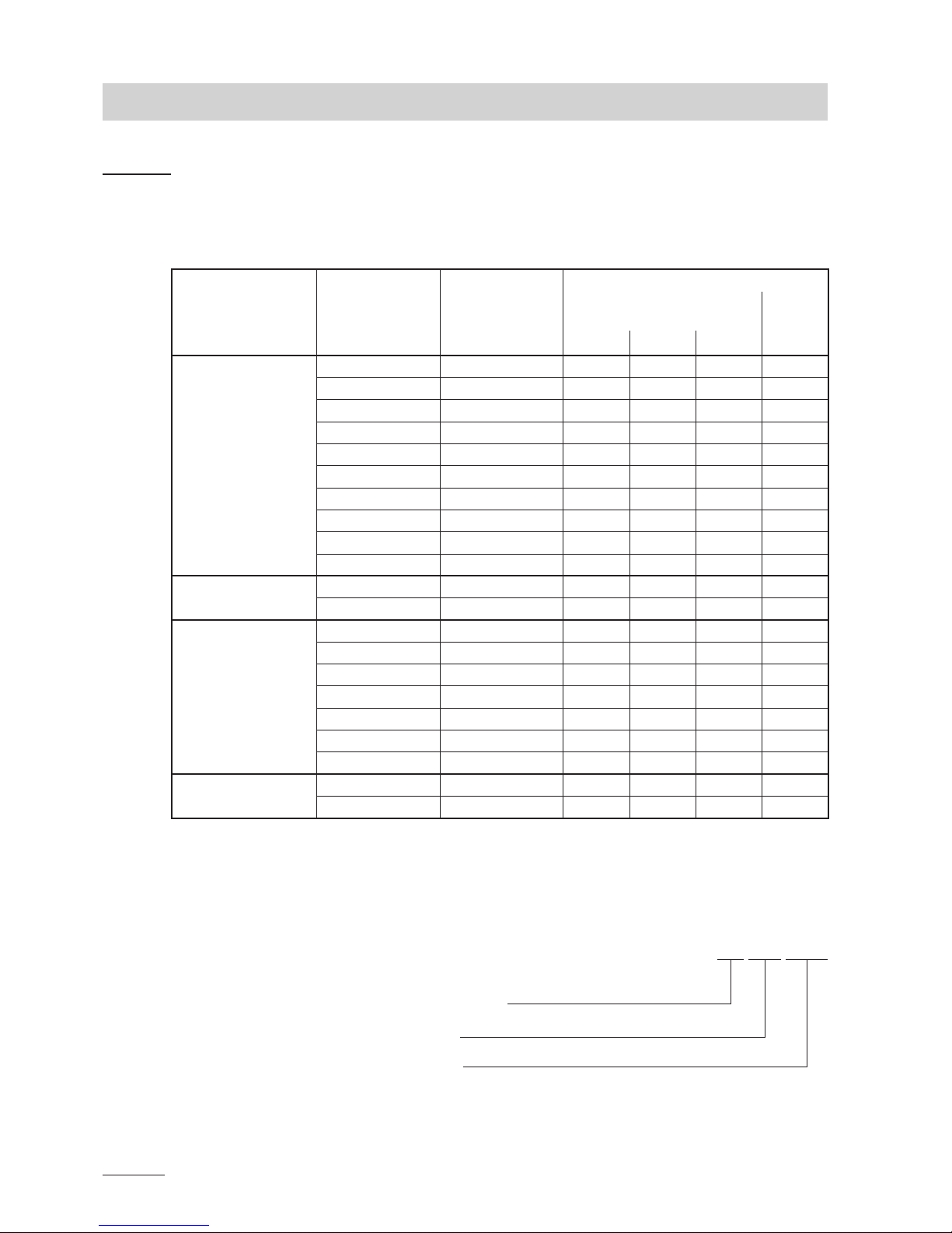
3.1 Models overview 8
3.2 Identicationoftheunit 9
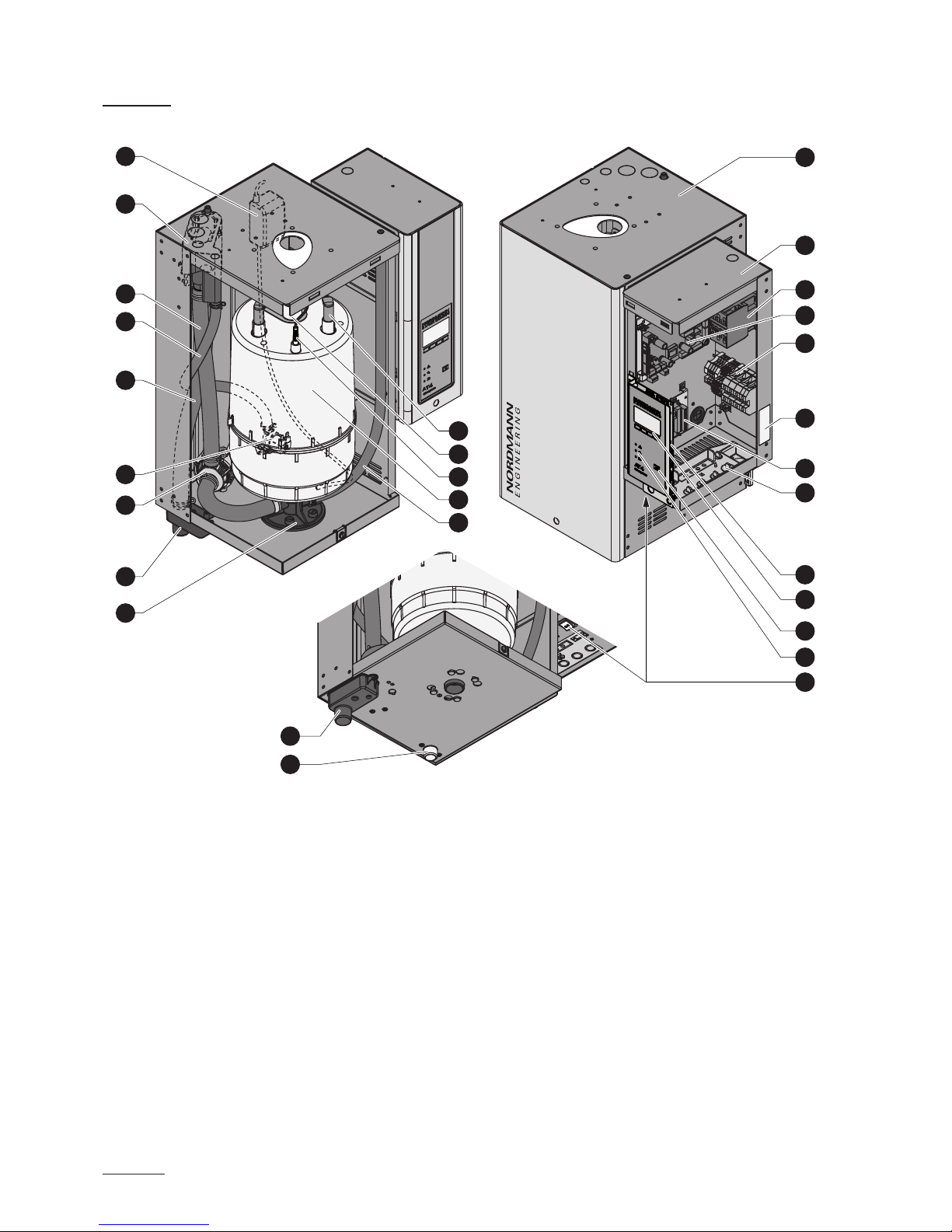
3.3 Steamhumidierconstruction 10
3.4 Functional description 11
3.5 Humidicationsystemoverview 13
4 Operation 17
4.1 Commissioning 17
4.2 Notes on operation 18
4.2.1 Functionofthedisplayandoperatingelements 18
4.2.2 Remoteoperatingandfaultindication 19
4.2.3 Notes on the operation at ambient
temperatures≤0°C 19
4.2.4 Inspections during operation 19
4.3 Carrying out manual draining 20
4.4 Takingtheunitoutofoperation 20
5 Working with the unit control 21
5.1 Factory settings 21
5.2 Operating the control unit and menu overview 22
5.3 Interrogationoftheoperatinginformationin
the indication level 23
5.4 Unit settings 24
5.4.1 Launching the unit settings menu 24
5.4.2 Selecting the dialogue language 24
5.4.3 Control settings 24
5.4.3.1 Selecting the signal source 25
5.4.3.2 Selecting the regulation mode 25
5.4.3.3 Selecting the control signal 25
5.4.3.4 Conguringhumiditysetpoint 26
5.4.3.6 Settingtheproportionalrangefortheinternal
P/PI controller 27
5.4.3.7 SettingtheintegraltimefortheinternalPIcontroller 27
5.4.3.8 Activating/Deactivating the supply air limitation 27
5.4.3.9 Selecting the supply air limitation signal 28
5.4.3.10 Settingthelowerlimitvalueforthe
supply air limitation 28
5.4.3.11 Settingtheupperlimitvalueforthe
supply air limitation 28
5.4.4 Selecting the cylinder type 29
5.4.5 ConguringtheSCsystem 29
5.4.5.1 Activating/deactivating the SC system 29
5.4.5.2 SettingtheoperationtimeoftheSC-Pump 30
5.4.6 Conguringthecapacitylimitation 30
5.4.7 ConguringtheOn/Offtimer 32
5.4.8 Water management settings 33
5.4.8.1 Selectingtheconductivityrangeofthesupplywater 33
5.4.8.2 Settingthedrainfactor 33
5.4.8.3 Settingtheoperatingmodeforstandbyoperation 34
5.4.8.4 Activating/Deactivatingtheforceddraining 36
5.4.8.5 Settingthetimeofoperationafterwhicha
forceddrainingtakesplace 37
5.4.9 Setting the date 37
5.4.10 Setting the time 37
5.4.11 Setting the display contrast 37
5.5 Modbus settings 38
5.5.1 SettingsforModbusnetworks 38
5.5.2 Settingsforthecommunicationwiththe
optional remote terminal 39
Contents
5.6 Diagnosticfunctions 40
5.6.1 Interrogationoftheerrorhistory 40
5.6.2 Interrogationofunitinformation 41
5.6.3 Performingremoterelaytests 42
5.6.4 PerformingModuletests 42
5.7 Working with the remote terminal 43
5.7.1 Menu overview remote terminal 43
5.7.2 Remote terminal settings 44
5.7.2.1 Selecting the dialogue language 44
5.7.2.2 Settingthenumberofhumidiersconnected
to the remote terminal 44
5.7.2.3 Interrogationoftheerrorhistoryofthe
remote terminal 44
5.7.2.4 Resettingtheerrorhistorylistofthe
remote terminal 45
5.7.2.5 Setting the baudrate 45
5.7.2.6 Setting the display contrast 45
6 Maintenance 46
6.1 Important notes on maintenance 46
6.2 Maintenance list 47
6.3 Removingandinstallingpartsformaintenance 48
6.3.1 Removalandinstallationofthesteamcylinder 48
6.3.2 Removalandinstallationofthedraincup 51
6.3.3 Removalandinstallationofthewatercup
and the water hoses 52
6.3.4 Removalandinstallationofthedrainpump 53
6.3.5 Removalandinstallationoftheinletvalve 54
6.3.6 Removalandinstallationofthecylinderreceptacle 55
6.4 Notes on cleaning the unit components 56
6.5 Notes on cleaning agents 58
6.6 Resetting the maintenance indication 58
7 Fault elimination 59
7.1 Fault indication 59
7.2 Malfunctionlists 60
7.2.1 Systemfaults 60
7.2.2 Unitfaults 61
7.3 Resetting the error indication (red LED lights) 63
7.4 Notesonfaultelimination 63
7.5 Replacing the backup battery on the control board 64
8 Taking out of service/Disposal 65
8.1 Takingoutofservice 65
8.2 Disposal/Recycling 65
9 Productspecications 66
9.1 Technical data 66
9.2 Wiring diagram Nordmann AT4 67
9.2.1 Wiring diagram Nordmann AT4 single units 67
9.2.2 Wiring diagram Nordmann AT4 double units 68

4
1 Introduction
1.1 To the very beginning
We thank you for having purchased the steam humidier Nordmann AT4.
The steam humidier Nordmann AT4 incorporates the latest technical ad
van ces and meets all recognized safety standards. Nevertheless, improper
use of the Nordmann AT4 may result in danger to the user or third parties
and/or impairment of material assets.
To ensure a safe, proper, and economical operation of the steam humidier
Nordmann AT4, please observe and comply with all information and safety
instructions contained in the present operating instructions.
If you have questions, which are not or insufciently answered in this
documentation, please contact your Nordmann supplier. They will be glad
to assist you.
1.2 Notes on the operating instructions
Limitation
The subject of these operating instructions is the steam humidier
Nordmann AT4. The various accessories are only described insofar as this
is necessary for proper operation of the equipment. Further information on
accessories can be obtained in the respective instructions.
These operating instructions are restricted to the commissioning, opera-
tion, servicing and trouble shooting of the steam humidier Nordmann
AT4 and is meant for well trained personnel being sufciently qualied
for their respective work.
These operating instructions are supplemented by various separate items
of documentation (installation instructions, spare parts list, manuals for ac
cessories, etc.). Where necessary, appropriate crossreferences are made
to these publications in the present documentation.

5
Explanation of the symbols used in this manual
CAUTION!
The catchword “CAUTION” designates notes in this documentation that, if
neglected, may cause damage and/or malfunction of the unit or other
material assets.
WARNING!
The catchword “WARNING” used in conjunction with the general caution
symbol designates safety and danger notes in this documentation that, if
neglected, may cause to injury to persons.
DANGER!
The catchword “DANGER” used in conjunction with the general caution
symbol designates safety and danger notes in this documentation that, if
neglected, may lead to severe injury or even death of persons.
Safekeeping
Please safeguard these operating instructions in a safe place, where it can
be immediately accessed. If the equipment changes hands, the documenta
tion should be passed on to the new operator.
If the documentation gets mislaid, please contact your Nordmann sup
plier.
Language versions
The present operating instructions are available in various languages. Please
contact your Nordmann supplier for information.
Copyright protection
The present operating instructions are protected under the Copyright Act.
Passingon and reproduction of the manual (or part thereof) as well as ex
ploitation and communication of the contents are prohibited without written
permission by the manufacturer. Violation of copyright terms is subject to
legal prosecution and arises liability for indemnication.
The manufacturer reserves the right to fully exploit commercial patent
rights.

6
2 For your safety
General
Every person working with the Nordmann AT4 must have read and under
stood the present operating instructions before carrying out any work.
Knowing and understanding the contents of the operating instructions is a
basic requirement for protecting the personnel against any kind of danger,
to prevent faulty operation, and to operate the unit safely and correctly.
All ideograms, signs and markings applied to the unit must be observed
and kept in readable state.
Qualication of personnel
All actions described in the present operating instructions (operation, main
tenance, etc.) must be carried out only by well trained and sufciently
qualied personnel authorised by the owner.
For safety and warranty reasons any action beyond the scope of this
manuals must be carried out only by qualied personnel authorised by the
manufacturer.
It is assumed that all persons working with the Nordmann AT4 are familiar
and comply with the appropriate regulations on work safety and the preven
tion of accidents.
Intended use
The steam humidier Nordmann AT4 is intended exclusively for air humidi-
cation via a steam distributor or a fan unit approved by the manufac-
turer within the specied operating conditions (see chapter 9 “Product
specications”). Any other type of application without the express written
consent of the manufacturer is considered as not conforming with the intended
purpose and may lead to the Nordmann AT4 becoming dangerous.
Operation of the equipment in the intended manner requires that all the
information in these instructions is observed (in particular the safety
instructions).

7
Danger that may arise from the unit
DANGER! Danger of electric hazard!
One may get in touch with live parts when the unit is open. Touching
live parts may cause severe injury or danger to life.
Prevention: Before carrying out any work set the Nordmann AT4 out of
operation as described in chapter 4.4 (switch off the unit, disconnect it
from the mains and stop the water supply) and secure the unit against
inadvertent powerup.
WARNING! Danger of burning!
The Nordmann AT4 produces steam. When producing steam, the
steam cylinder inside the humidier gets very hot (up to 100 °C). If
the unit is opened immediately after having produced steam there
is danger of burning when touching the steam cylinder.
Prevention: Before carrying out any work set the Nordmann AT4 out of
operation as described in chapter 4.4, then wait until the steam cylinder
has cooled down sufciently thus preventing danger of burning.
Behaviour in case of danger
If it is suspected that safe operation is no longer possible, then the
Nordmann AT4 should immediately be shut down and secured against
accidental power-up according to chapter 4.4. This can be the case
under the following circumstances:
– if the Nordmann AT4 is damaged
– if the electrical installations are damaged
– if the Nordmann AT4 is no longer operating correctly
– if connections and/or piping are not sealed
All persons working with the Nordmann AT4 must report any alterations to
the unit that may affect safety to the owner without delay.
Prohibited modications to the unit
No modications must be undertaken on the Nordmann AT4 without the
express written consent of the manufacturer.
For the replacement of defective components use exclusively original ac-
cessories and spare parts available from your Nordmann supplier.

8
3 Product Overview
3.1 Models overview
Steam air humidiers Nordmann AT4 are available with different heating
voltages and steam capacities ranging from 5 kg/h up to a maximum
of 130 kg/h.
Heating voltage ** Max. steam
capacity
in kg/h
Model
Nordmann AT4
Unit size
Single
unit
Double
unit
small medium large large
400V3
(400 V/3~/50...60 Hz)
5534 x
8834 x
15 1534 x
23 2364 x
32 3264 x
45 4564 x
64 6464 x
65 6564 x
90 9064 x
130 13064 x
400V2
(400 V/2~/50...60 Hz)
5 524 x
8 824 x
230V3
(230 V/3~/50...60 Hz)
5532 x
8832 x
15 1532 x
23 2362 x
32 3262 x
46 4662 x
64 6462 x
230V1
(230 V/1~/50...60 Hz)
5 522 x
8 822 x
** Other heating voltages on request
Key model designation
Example:
Nordmann AT4 4564 400V3
Product designation:
Unit model:
Heating voltage:
400V/3~/50...60Hz: 400V3
400V/2~/50...60Hz: 400V2
230V/3~/50...60Hz: 230V3
230V/1~/50...60Hz: 230V1

9
3.2 Identicationoftheunit
The identication of the unit is found on the type plate:
Walter Meier (Climate International) Ltd. 3562 Pfäfkon
Type: AT4 4564 Ser.Nr.: XXXXXXX 02.10
Heating voltage: 400V / 3~ / 50...60Hz Power: 33.8 kW
Steam capacity: 45.0 kg/h Ctrl. Voltage: 230V / 1~ / 50...60Hz
Water pressure: 1...10 bar
Made in Switzerland
Type designation Serial number (7 digits) Month/Year
Heating voltage
Maximum steam capacity per unit
Admissible water supply pressure
Power consumption
Control voltage
Field with certication symbols
Module A Module B

10
3.3 Steamhumidierconstruction
1 Steam cylinder compartment
2 Control compartment
3 Main contactor
4 Power board
5 Connecting terminals
6 Type plate
7 Remote operating and fault indication board (option)
8 Cable openings
9 Control board with CF Card
10 Display and control unit
11 Drain key
12 Operation status indicators
13 Unit switch
14 SC pump
15 Water cup
16 Filling and draining hose
17 Water supply hose
18 Overow hose
19 Inlet valve
20 Drain pump
21 Drain cup
22 Steam cylinder receptacle
23 Drain hose (manual drain)
24 Steam cylinder
25 Level sensor
26 Steam outlet
27 Electrode plug
28 Drain connector
29 Water supply connector
3
2
1
4
5
7
8
10
12
11
9
15
14
18
22
21
16
17
20
19
24
23
27
25
26
28
29
13
6
gure shows medium unit

11
3.4 Functional description
The steam humidier Nordmann AT4 is a pressureless steam generator
that utilizes an electrode heating. The steam humidier Nordmann AT4 is
designed for air humidication via a steam distributor (steam distribution
pipe, fan unit or steam distribution system MultiPipe).
Steam generation
Any time steam is requested, the electrodes are supplied with voltage via
main contactor. Simultaneously, the inlet valve opens and water enters the
steam cylinder from the bottom via water cup and supply line. As soon as the
electrodes come in contact with the water, current begins to ow between
the electrodes, eventually heating and evaporating the water. The more the
electrode surface is exposed to water, the higher is the current consumption
and thus the steam capacity.
Steam distribution pipe
Condensate hose
with siphon
Steam hose
Water cup
Overow hose
Filling and
draining hose
Water supply
hose
Inlet valve
steam cylinder receptacle
Steam cylinder
Electrodes
Level sensor
Drain hose
Control board
Power board
Unit switch
Main contactor
Current sensor
Drain pump
SC pump
Connecting terminals

12
Upon reaching the requested steam capacity, the inlet valve closes. If the
steam generation decreases below a certain percentage of the required
capacity, due to lowering of the water level (e.g. because of the evapora
tion process or drainage), the inlet valve opens until the required capacity
is available again.
If the required steam capacity is lower than the actual output, the inlet valve
is closed until the desired capacity is achieved by lowering of the water level
(evaporation process).
Level monitoring
A sensor provided in the steam cylinder cover detects when the water level
gets too high. The moment the sensor comes in contact with water, the
inlet valve closes.
Drainage
As a result of the evaporation process, the conductivity of the water increases
due to an escalating mineral concentration. Eventually, an inadmissibly high
current consumption would take place if this concentration process were
permitted to continue. To prevent this concentration from reaching a value,
unsuitably high for the operation, a certain amount of water is perio dically
drained from the cylinder and replaced by fresh water.
Lime management
The interval controlled SC pump blows air into the steam cylinder. Thus
keeping the solved minerals in the water in motion as a result they are
discharged with the automatic drain cycles.
Control
The steam production can be controlled with the internal or an external
continuous controller or an external humidistat (24 VDC On/Off control).

13
3.5 Humidicationsystemoverview
System overview duct humidication (single units)
1 Steam humidier
2 Steam connector
3 Water supply connector
4 Water drain connector
5 Water connection hose G 3/4" G 3/8"
(included in the delivery)
6 Filter valve (accessory “Z261”)
7 Manometer (installation recommended)
8 Funnel with siphon (building side)
9 Water drain hose (included in the delivery)
10 Service switch control voltage supply (building side)
11 Service switch heating voltage supply (building side)
12 Steam hose (accessory “DS22”/“DS35”)
13 Condensate hose (accessory “KS10”)
14 Steam distribution pipe (accessory “DV41..”/“DV71..”)
15 Steam distribution system (accessory “MultiPipe”)
16 Continuous humidity controller or humidistat
17 Safety humidistat
ONOFF
ONOFF
11
10
1
2
3
4
5
6
7
DS35
DS22
Z261
12
13
16
14
KS10
DV41
DV71
17
8
9
ONOFF
ONOFF
11
10
17
1
3
5
6
7
Z261
8
2
13
4
DS35
KS10
12
14
DV71
16
9
15
MultiPipe
System 1
System 2
125...1250 µS/cm
1...10 bar
1...40 °C

14
15
DV71
ONOFF
ONOFF
ONOFF
10
11
12
KS10
18
9
8
14
1
2
3
4
6
7
Z261
5
8
17
DS35
13
16
MultiPipe
System 4
System overview duct humidication (double units)
1 Steam humidier
2 Steam connector
3 Water supply connectors
4 Water drain connector
5 Water connection hose G 3/4" G 3/8"
(included in the delivery)
6 Filter valve (accessory “Z261”)
7 Manometer (installation recommended)
8 Funnel with siphon (building side)
9 Water drain hose (included in the delivery)
10 Service switch control voltage supply (building side)
11 Service switch heating voltage supply module A (building side)
12 Service switch heating voltage supply module B (building side)
13 Steam hose (accessory “DS35”)
14 Condensate hose (accessory “KS10”)
15 Steam distribution pipe (accessory “DV71..”)
16 Steam distribution system (accessory “MultiPipe”)
17 Continuous humidity controller or humidistat
18 Safety humidistat
125...1250 µS/cm
1...10 bar
1...40 °C

15
ONOFF
ONOFF
16
17
Turbo 32
13
KS10
15
DS35
12
11
10
1
2
3
4
5
6
7
Z261
8
9
14
FAN4 N-S
FAN4 N-M
ONOFF
11
1
3
5
6
7
Z261
2
4
DS35
13
Turbo 65
Turbo 45
15
ONOFF
10
14
KS10
8
9
System overview room humidication (single units)
1 Steam humidier
2 Steam connector
3 Water supply connector
4 Water drain connector
5 Water connection hose G 3/4" G 3/8"
(included in the delivery)
6 Filter valve (accessory “Z261”)
7 Manometer (installation recommended)
8 Funnel with siphon (building side)
9 Water drain hose (included in the delivery)
10 Service switch control voltage supply (building side)
11 Service switch heating voltage supply (building side)
12 Steam hose (accessory “DS35”/“Z10”)
13 Condensate hose (accessory “KS10”)
14 Ventilation unit (accessory “FAN4 N...”)
15 Ventilation unit (accessory “Turbo..”)
16 Continuous humidity controller or humidistat
17 Safety humidistat
125...1250 µS/cm
1...10 bar
1...40 °C

16
System overview room humidication (double units)
125...1250 µS/cm
1...10 bar
1...40 °C
1 Steam humidier
2 Steam connector
3 Water supply connectors
4 Water drain connector
5 Water connection hose G 3/4" G 3/8"
(included in the delivery)
6 Filter valve (accessory “Z261”)
7 Manometer (installation recommended)
8 Funnel with siphon (building side)
9 Water drain hose (included in the delivery)
10 Service switch heating voltage supply (building side)
11 Service switch heating voltage supply module A (building side)
12 Service switch heating voltage supply module B (building side)
13 Steam hose (accessory “DS35”)
14 Condensate hose (accessory “KS10”)
15 Ventilation unit (accessory “Turbo..”)
16 Continuous humidity controller or humidistat
17 Safety humidistat
16
17
ONOFF
ONOFF
9
8
14
KS10
ONOFF
10
11
12
14 KS10
Turbo 45
15
Turbo 45
Turbo 65
Turbo 65
15
1
4
6
7
Z261
3
2
5
DS35
13

17
4 Operation
4.1 Commissioning
Proceed as follows when putting the steam humidier into operation:
1. Examine the steam humidier and installation for possible damage.
DANGER!
Damaged devices or devices with damaged installation may present
danger to human life or cause severe damage to material assets.
Damaged units and/or units with damaged or faulty installation
must not be operated.
2. Check whether the front panels are mounted and xed with the
screws.
3. Open the shutoff valve in the water supply line.
4. Verify the set humidity value at the humidity controller or at the humidi
stat, and readjust as required.
5. Switch on the service switches for mains supplies (heating and control
voltage).
6. Actuate the unit switch of the steam humidier.
The steam humidier carries out a system test, during which all three
LED’s light up.
If a failure occurs on the system test, a corresponding error message is
shown in the display.
After the system test the unit is in normal operation mode. The display
shows the standard operating display (rst page of the indication level).
Note: The contents of the standard operating display depends on the actual
operating status and on the conguration of the Nordmann AT4 and can
differ from the opposite display.
As soon as the humidity controller or the humidistat requires humidity, power
is switched on for heating. The inlet valve opens (slight delay) and the steam
cylinder lls with water. As soon as the submerged electrodes heat the water
up the green LED lights up and after a few minutes (approx. 5–10 minutes,
depending on the conductivity of the water) steam is produced.
Note: If the Nordmann AT4 is operated with water of low conductivity it may
happen that the maximum steam capacity is not reached in the rst few
hours of operation. This is normal. As soon as the conductivity has reached
a sufcient level (due to the vaporisation process) the humidier will reach
the maximum steam capacity.
Menu
AT4 130kg/h 400V3
Standby
2011-08-31 12.00.00
Menu
AT4 130kg/h 400V3
Demand :28%
2011-08-31 12.00.00
AT4
STARTUP:
INIT MODULE

18
4.2 Notes on operation
4.2.1 Function of the display and operating elements
Display and control unit
Function: Conguration of the Nordmann AT4
Indication of operating parameters
Reset of maintenance counter
Performing diagnostic functions
red LED “Malfunction”
Function: The LED lights in case of a severe malfunction of
the unit (Error status). Further operation is not pos
sible any longer. The error message is shown in the
display, see chapter 7).
The LED ashes alternately with the green LED if
the external safety chain (e.g. ventilation interlock
has triggered) is open. As soon as the safety chain
is closed again, the indication disappears.
yellow LED “Maintenance”
Function: The LED lights if the steam cylinder must be re
placed.
green LED “Humidication”
Function: The LED lights if the unit produces steam.
The LED ashes alternately with the red LED if the
external safety chain (e.g. ventilation interlock has
triggered) is open. As soon as the safety chain is
closed again, the indication disappears.
Drain key
Function: Calls up the dialogue for the manual draining
Unit switch
Function: Switches the unit on and off. The switch is illumi
nated when the unit is on.

19
4.2.2 Remote operating and fault indication
If your unit is equipped with the optional operating and fault indication PCB
(option “RFI”) the following operating status are shown remotely:
Activated remote
indication relay
When? Display on unit
“Error” A error is present, further operation is
normally not possible any longer, the
heating voltage is interrupted.
Red LED lights and an
error message is shown
in the display.
“Service” The steam cylinder is spent and must be
replaced. The unit remains operational
for a certain time.
Yellow LED lights and
the service message is
shown in the display.
“Steam” Steam demand/Steam production Green LED lights and the
standard operating dis
play is shown.
“Unit on” Unit is switched on. Unit switch lights and the
standard operating dis
play is shown.
4.2.3 Notesontheoperationatambienttemperatures≤0°C
If during operation ambient temperatures ≤ 0°C must be expected (opera
tion of the Nordmann AT4 in a protective housing outside the building), the
standby draining function must be set to “Full” and the period of time in
standby operation after which an automatic cylinder draining takes place
must be set to 1 hour (see chapter 5.4.8.3).
4.2.4 Inspections during operation
During operation the Nordmann AT4 and the humidication system have to
be inspected weekly. On this occasion check the following:
• the water and steam installation for any leakage.
• the steam humidier and the other system components for correct xing
and any damage.
• the electric installation for any damage.
If the inspection reveals any irregularities (e.g. leakage, error indication)
or any damaged components take the Nordmann AT4 out of operation as
described in chapter 4.4. Then, contact your Nordmann representative.

20
4.3 Carrying out manual draining
Proceed as follows to drain the unit manually:
1. Briey press the drain key. The draining dialogue appears in the
display.
Note: With double units both cylinders can be drained separately in the
draining dialogue.
2. Press the <Start> key. The heating voltage is interrupted and the drain
pump starts. The yellow LED ashes.
To stop the drain cycle briey press the <Stop> key.
Note: by pressing the <Esc> key the display unit returns to the indication
level. A draining cycle in progress is interrupted automatically.
4.4 Taking the unit out of operation
In order to take the steam humidier out of operation, perform the following
steps:
1. If the unit has to be switched off because of a malfunction, please note
the error code of the actual error message shown in the display.
2. Close the shutoff valve in the water supply line.
3. Start manual draining (see chapter 4.3) and wait until the steam cylinder(s)
is/are empty.
Note: If the drain pump is defective, the steam cylinder(s) is/are to be
emptied manually via the manual draining hose.
4. Actuate the unit switch.
5. Disconnect steam humidier from the mains: Switch off all service
switches to mains supplies (heating and control voltage) and secure
switches in “off” position against accidentally being switched on, or
clearly mark the switches.
6. If ambient temperatures ≤ 0°C must be expected when the unit is out
of operation (operation of the Nordmann AT4 in a protective housing
outside the building): drain the water supply pipe and the water lter
(lter valve).
WARNING! Danger of burning!
If steam was produced just before the unit is taken out of operation, wait
before opening the unit and let the steam cylinder cool down to prevent
danger of burning.
Start
Manual Drain
Press START or STOP
Cyl.A Cyl.BCyl.B
StartEsc
Other manuals for AT4 Series
1
Table of contents
Other Nordmann Humidifier manuals
Popular Humidifier manuals by other brands

Artisana
Artisana SuperVap operating instructions

White Rodgers
White Rodgers HFT2700 Installation instructions and mounting template

Wine Guardian
Wine Guardian 99H0174-21 Installation, operation and maintenance manual

Arlec
Arlec AEC008 instruction manual

Vornado
Vornado Ultrasonic Humidifier owner's manual

Bort
Bort Silver Air manual