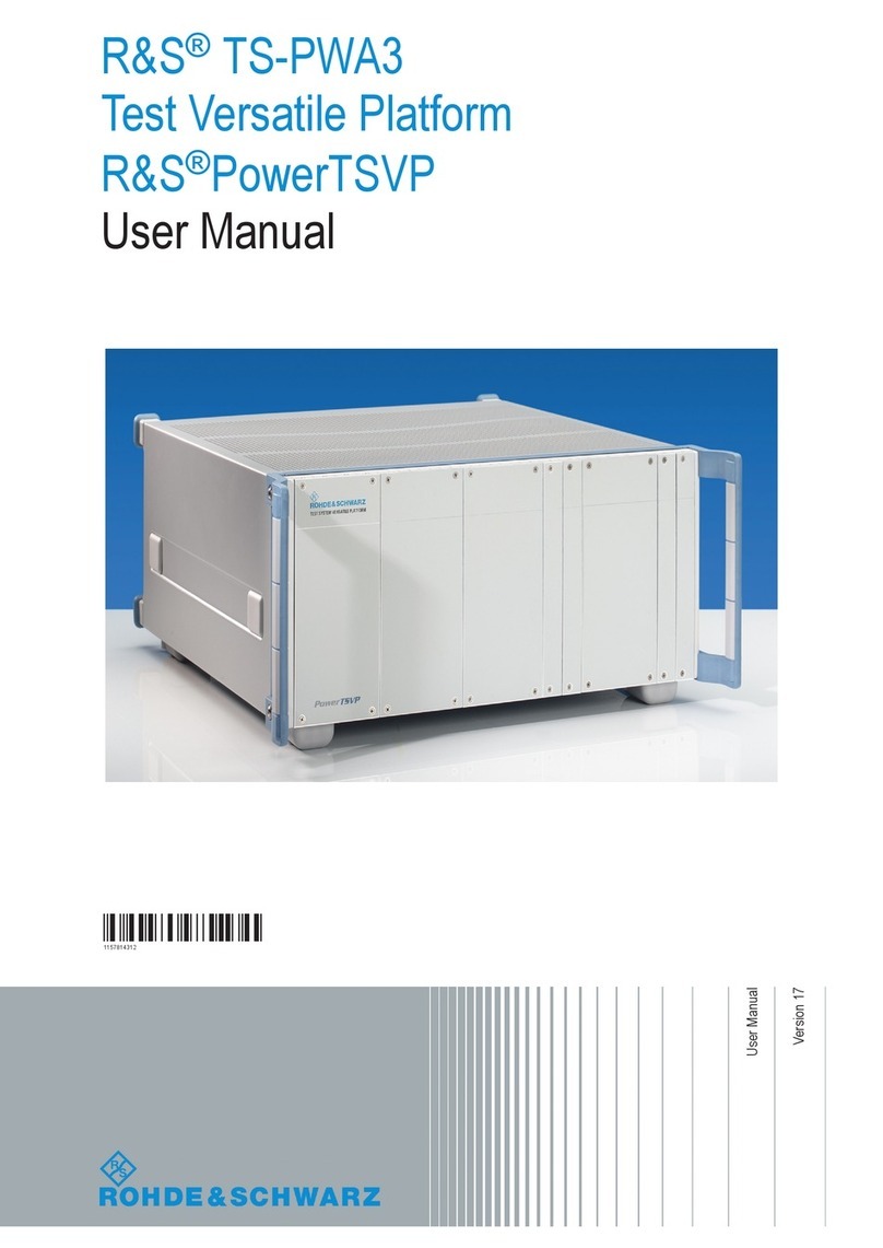
Nordson Sealant Equipment PRO-METER V2K Reference guide

PRO-METER® V2K
CUSTOMER PRODUCT MANUAL
COMPONENT MANUAL P/N: 7440274
ISSUED /2017
For parts and technical support, call the Nordson Sealant Equipment customer support at
(734) 459-8600, or contact your local Nordson Sealant Equipment Representative.
This document is subject to change without notice.
Please check with customer service for the latest version.
Nordson Sealant Equipment٠Plymouth, Michigan٠U.S.A

Part 7440274 2017 Nordson Corporation
Nordson Corporation welcomes requests for information, comments, and
inquiries about its products. General information about Nordson can be
found on the Internet using the following address:
http://www.nordson.com.
Notice
This is a Nordson Corporation publication which is protected by copyright.
Original copyright date 08/2016. No part of this document may be
photocopied, reproduced, or translated to another language without the
prior written consent of Nordson Corporation. The information contained
in this publication is subject to change without notice.
Trademarks
Nordson and the Nordson logo are registered trademarks of Nordson
Corporation.
Pro-Meter is a trademark of Nordson Corporation.
All other trademarks are the property of their respective owners.

Table of Contents i
Part 7440274
2017 Nordson Corporation
Table of Contents
Safety 1-1..................................................
Introduction 1-1.............................................
Qualified Personnel 1-1......................................
Intended Use 1-1...........................................
Regulations and Approvals 1-1...............................
Personal Safety 1-2.........................................
High−Pressure Fluids 1-3.....................................
Fire Safety 1-4.............................................
Grounding 1-5..............................................
Halogenated Hydrocarbon Solvent Hazards 1-6.................
Action in the Event of a Malfunction 1-6........................
Disposal 1-6...............................................
Description 2-1.............................................
Meter 2-1..................................................
Meter Assembly Standard Components 2-2....................
Meter Connections 3-1......................................
Connection Overview 3-1....................................
Electrical Harness Connectors 3-2..........................
Material, Air, And Other Connections 3-2....................
Specifications 4-1..........................................
Thread Locker Application 5-1..............................
Loctite Product Application, Cleanup, And Storage 5-2...........
Blind and Thru Holes 5-2..................................
Sealing Applications 5-2...................................
Cleanup 5-2.............................................
Storage 5-3..............................................

Table of Contents
ii
Part 7440274 2017 Nordson Corporation
System Setup and Calibration 6-1...........................
System Unpack 6-2.........................................
Air Line Routing 6-2.........................................
Electrical Wiring 6-2.........................................
Fluid Flow Path 6-2.........................................
HMI Pendant 6-2...........................................
Initial System Startup 6-3....................................
Adjustment And Calibration 6-6...............................
HMI Pendant Login 6-6....................................
Air Actuator Flow Adjustment 6-6...........................
Cylinder Position Sensor Calibration 6-7.....................
Linear Speed Control Calibration 6-7........................
Lead/Lag Calibration 6-8..................................
Low Level Sensor Calibration 6-9...........................
Pressure Transducer Calibration 6-10........................
Stroke Adjustment 6-11....................................
Operation 7-1..............................................
Dispense Mode Descriptions 7-2..............................
Auto Flow Mode 7-2......................................
Auto Shot Mode 7-2......................................
Manual Flow Mode 7-2....................................
Manual Shot Mode 7-2....................................
Operation 7-3..............................................
Maintenance 8-1...........................................
Consumables 8-2...........................................
Preparation For Maintenance and Service 8-3..................
Air Pressure Relief 8-3....................................
Material Pressure Relief 8-4...............................
Power Disconnect 8-6.....................................
Preventative Maintenance Schedule 8-7.......................
Troubleshooting 9-1........................................
Removal and Installation 10-1................................
Air Actuator 10-2.............................................
Removal 10-2.............................................
Installation 10-6...........................................
Ball Valve Assembly 10-8.....................................
Removal 10-8.............................................
Installation 10-11...........................................
Carriage 10-12...............................................
Removal 10-12.............................................
Installation 10-13...........................................
Cylinder Position Sensor (If Equipped) 10-14.....................
Removal 10-14.............................................
Installation 10-15...........................................
Gravity Tank (If Equipped) 10-16................................
Removal 10-16.............................................
Installation 10-18...........................................
Limit Switch 10-19............................................
At Metering Cylinder Housing 10-19...........................
Removal 10-19..........................................
Installation 10-20.........................................

Table of Contents iii
Part 7440274
2017 Nordson Corporation
At Strike Stop 10-21........................................
Removal 10-21..........................................
Installation 10-22.........................................
Linear Speed Control (If Equipped) 10-23........................
Removal 10-23.............................................
Installation 10-25...........................................
Low Level Sensor (If Equipped) 10-26............................
Removal 10-26.............................................
Installation 10-26...........................................
Metering Cartridge Assembly 10-27.............................
Removal 10-27.............................................
Installation 10-30...........................................
Micro PLC 10-32..............................................
Removal 10-32.............................................
Installation 10-34...........................................
Pneumatic Valve Manifold 10-35................................
Removal 10-35.............................................
Installation 10-37...........................................
Pneumatic Valve Manifold Solenoid 10-38........................
Removal 10-38.............................................
Installation 10-39...........................................
Power Supply Fuse 10-40......................................
Removal 10-40.............................................
Installation 10-42...........................................
Power Supply Cover 10-43.....................................
Removal 10-43.............................................
Installation 10-44...........................................
Power Supply Module 10-45....................................
Removal 10-45.............................................
Installation 10-46...........................................
Power Supply Switch 10-47....................................
Removal 10-47.............................................
Installation 10-47...........................................
Pressure Transducer (If Equipped) 10-48.........................
Removal 10-48.............................................
Installation 10-49...........................................
Disassembly and Assembly 11-1.............................
Metering Cartridge Assembly 11-2.............................
Disassembly 11-3.........................................
Assembly 11-12............................................
PanelView Specifications 12-1................................
PanelViewC800 12-1.......................................

Table of Contents
iv
Part 7440274 2017 Nordson Corporation
Common Screen Description Elements 13-1...................
Elements 13-1...............................................
Pilot Light Indicators 13-1...................................
Push Buttons 13-1.........................................
Push Buttons With Indicator Lights 13-1......................
Data Displays 13-2........................................
Data Entry Fields 13-2.....................................
Dashboard Indicators 13-2..................................
Bar Graphs 13-2..........................................
Typical Screen Layout 13-10...................................
Mode Indicator 13-10.......................................
Navigation Buttons 13-10...................................
Status Indicator 13-10.......................................
Title Bar 13-10.............................................
Screen Descriptions 14-1....................................
Normal Operation Screens 14-1...............................
Main Menu 14-1...........................................
Dispense 1 14-2..........................................
Dispense 2 14-3..........................................
Faults & Warnings 1 and 2 14-4.............................
Faults & Warnings 1 14-4................................
Faults & Warnings 2 14-5................................
Interlock Status 14-7.......................................
Material Pressure 14-8.....................................
Material Pressure History 14-9..............................
Meter Status 14-10.........................................
Options Setup 14-11.........................................
Purge Control 14-12........................................
Setup Login 14-14..........................................
Setup Screens 14-15..........................................
Confirm Exit To Config Mode 14-15...........................
Cylinder Setup 14-16........................................
Flow Mode Setup 14-17.....................................
Interlock Setup 14-18.......................................
Level 1 Setup Menu 14-19...................................
Level 2 Setup Menu 14-20...................................
Miscellaneous Setup 14-21..................................
Options Setup 14-22.........................................
Position Sensor Calibration 14-23.............................
Pressure Limits Setup 14-24.................................
Pressure Sensor Calibration 14-26............................
Pressure Setup 14-28.......................................
Purge Setup 14-29..........................................
Reset Password 14-30......................................
Stroke Setup 14-31.........................................
Valve Setup 14-32..........................................

Table of Contents v
Part 7440274
2017 Nordson Corporation
Parts 15-1...................................................
Introduction 15-1.............................................
Using the Illustrated Parts List 15-1..........................
3-Column Parts List 15-2.................................
Customer Product Manual 15-3.............................
Pro−Meter V2K Assembly Top Level Assembly 15-3............
Pro−Meter V2K Basic Assembly 15-6........................
Base Plate Assembly 15-16..................................
Cover Assembly 15-21......................................
Gravity Feed Tanks (If Equipped) 15-23.......................
HMI Pendant 15-25.........................................
Metering Cartridge Assembly 15-28..........................
Power Supply Assembly 15-30...............................
Optional Components 15-34.................................
Metering Cartridge Assembly Service Kit 15-34................


Safety 1-1
Part 7440274
2017 Nordson Corporation
Section 1
Safety
Introduction
Read and follow these safety instructions. Task- and equipment-specific
warnings, cautions, and instructions are included in equipment
documentation where appropriate.
Make sure all equipment documentation, including these instructions, is
accessible to all persons operating or servicing equipment.
Qualified Personnel
Equipment owners are responsible for making sure that Nordson
equipment is installed, operated, and serviced by qualified personnel.
Qualified personnel are those employees or contractors who are trained to
safely perform their assigned tasks. They are familiar with all relevant safety
rules and regulations and are physically capable of performing their
assigned tasks.
Intended Use
Use of Nordson equipment in ways other than those described in the
documentation supplied with the equipment may result in injury to persons
or damage to property.
Some examples of unintended use of equipment include:
Using incompatible materials
Making unauthorized modifications
Removing or bypassing safety guards or interlocks
Using incompatible or damaged parts
Using unapproved auxiliary equipment
Operating equipment in excess of maximum ratings
Regulations and Approvals
Make sure all equipment is rated and approved for the environment in which
it is used. Nordson equipment warranties may be voided if instructions for
installation, operation, and service are not followed.
All phases of equipment installation must comply with all federal, state, and
local codes.

Safety
1-2
Part 7440274 2017 Nordson Corporation
Personal Safety
To prevent injury, follow these instructions.
Do not operate or service equipment unless you are qualified.
Do not operate equipment unless safety guards, doors, or covers are
intact and automatic interlocks are operating properly. Do not bypass or
disarm any safety devices.
Keep clear of moving equipment. Before adjusting or servicing any
moving equipment, shut off the power supply and wait until the
equipment comes to a complete stop. Lock out power and secure the
equipment to prevent unexpected movement.
Relieve (bleed off) hydraulic and pneumatic pressure before adjusting or
servicing pressurized systems or components. Disconnect, lock out, and
tag switches before servicing electrical equipment.
While operating manual dispense valves, make sure you are grounded.
Wear electronically conductive gloves or a grounding strap connected to
the dispense valve handle or other true earth ground. Do not wear or
carry metallic objects such as jewelry or tools.
If you receive even a slight electrical shock, shut down all electrical and
electrostatic equipment immediately. Do not restart the equipment until
the problem has been identified and corrected.
Obtain and read Safety Data Sheets (SDS) for all materials used. Follow
the manufacturer’s instructions regarding the safe handling and use of
materials. Use recommended personal protection devices.
Make sure the dispensing area is adequately ventilated.
To prevent injury, be aware of less-obvious dangers in the workplace
that often cannot be completely eliminated, such as hot surfaces, sharp
edges, energized electrical circuits, and moving parts that cannot be
enclosed or otherwise guarded for practical reasons.

Safety 1-3
Part 7440274
2017 Nordson Corporation
High−Pressure Fluids
High pressure fluids, unless they are safely contained, are extremely
hazardous. Always relieve fluid pressure before adjusting or servicing high
pressure equipment. A jet of high−pressure fluid can cut like a knife and
cause serious bodily injury, amputation, or death. Fluids penetrating the skin
can also cause toxic poisoning. If you suffer a fluid injection injury, seek
medical care immediately.
WARNING: Any injury caused by high pressure liquid can be serious. If you
are injured or even suspect an injury:
Go to an emergency room immediately.
Tell the doctor that you suspect an injection injury.
Inform medical staff regarding the type of material dispensed.
MEDICAL ALERT −AIRLESS SPRAY WOUNDS: NOTE TO A PHYSICIAN
Injection into the skin is a serious traumatic injury. It is important to treat the
injury surgically as soon as possible. Do not delay treatment to research
toxicity. Toxicity is a concern with some exotic coatings injected directly into
the bloodstream. Consultation with a plastic surgeon or a reconstructive
hand surgeon may be advisable. The seriousness of the wound depends on
where the injury is on the body, whether the substance hit something on its
way in and deflected causing more damage, and many other variables
including skin micro−flora residing in the plant or gun which are blasted into
the wound. If the injected material contains acrylic latex and titanium dioxide
which damages the tissue’s resistance to infection, bacterial growth will
flourish. The treatment that doctors recommend for an injection injury to the
hand includes immediate decompression of the closed vascular
compartments of the hand to release the underlying tissue distended by the
injection material, judicious wound debridement, and immediate antibiotic
treatment.

Safety
1-4
Part 7440274 2017 Nordson Corporation
Fire Safety
To avoid a fire or explosion, follow these instructions:
Shut down all equipment immediately if you notice static sparking or
arcing. Do not restart the equipment until the cause has been identified
and corrected.
Do not smoke, weld, grind, or use open flames where flammable
materials are being used or stored.
Do not heat materials to temperatures above those recommended by
the manufacturer. Make sure heat monitoring and limiting devices are
working properly.
Provide adequate ventilation to prevent dangerous concentrations of
volatile materials or vapors. Refer to local codes or your SDS for
guidance.
Do not disconnect live electrical circuits while working with flammable
materials. Shut off power at a disconnect switch first to prevent sparking.
Know where emergency stop buttons, shutoff valves, and fire
extinguishers are located. If a fire starts in a spray booth, immediately
shut off the spray system and exhaust fans.
Shutoff electrostatic power and ground the charging system before
adjusting, cleaning, or repairing electrostatic equipment.
Clean, maintain, test, and repair equipment according to the instructions
in your equipment documentation.
Use only replacement parts that are designed for use with original
equipment. Contact your Nordson representative for parts information
and advice.

Safety 1-5
Part 7440274
2017 Nordson Corporation
Grounding
WARNING: Operating faulty electrostatic equipment is hazardous and can
cause electrocution, fire, or explosion. Make resistance checks part of your
periodic maintenance program. If you receive even a slight electrical shock
or notice static sparking or arcing, shut down all electrical or electrostatic
equipment immediately. Do not restart the equipment until the problem has
been identified and corrected.
Grounding inside and around the booth openings must comply with NFPA
requirements for Class II, Division 1 or 2 Hazardous Locations. Refer to
NFPA 33, NFPA 70 (NEC articles 500, 502, and 516), and NFPA 77.
All electrically conductive objects in spray areas shall be electrically
connected to ground with a resistance of not more than 1 megohm as
measured with an instrument that applies at least 500 volts to the circuit
being evaluated.
Equipment to be grounded includes, but is not limited to, the floor of the
spray area, operator platforms, hoppers, photoeye supports, and
blow-off nozzles. Personnel working in the spray area must be
grounded.
There is ignition potential from a charged human body. Personnel
standing on a painted surface, such as an operator platform, or wearing
non-conductive shoes, are not grounded. Personnel must wear shoes
with conductive soles or use a ground strap to maintain a connection to
ground when working with or around electrostatic equipment.
Operators must maintain skin-to-handle contact between their hand and
the gun handle to prevent shocks while operating manual electrostatic
spray guns. If gloves must be worn, cut away the palm or fingers, wear
electrically conductive gloves, or wear a grounding strap connected to
the gun handle or other true earth ground.
Shut off electrostatic power supplies and ground gun electrodes before
making adjustments or cleaning powder spray guns.
Connect all disconnected equipment, ground cables, and wires after
servicing equipment.

Safety
1-6
Part 7440274 2017 Nordson Corporation
Halogenated Hydrocarbon Solvent Hazards
Do not use halogenated hydrocarbon solvents in a pressurized system that
contains aluminum components. Under pressure, these solvents can react
with aluminum and explode, causing injury, death, or property damage.
Halogenated hydrocarbon solvents contain one or more of the following
elements:
Element Symbol Prefix
Fluorine F “Fluoro−”
Chlorine Cl “Chloro−”
Bromine Br “Bromo−”
Iodine I “Iodo−”
Check your material SDS or contact your material supplier for more
information. If you must use halogenated hydrocarbon solvents, contact
your Nordson Sealant representative for information about compatible
Nordson Sealant Equipment components.
Action in the Event of a Malfunction
If a system or any equipment in a system malfunctions, shut off the system
immediately and perform the following steps:
Disconnect and lock out electrical power. Close pneumatic shutoff
valves and relieve pressure.
Identify the reason for the malfunction and correct it before restarting the
equipment.
Disposal
Dispose of equipment and material used in operation and servicing
according to federal, state, and local codes.

Description 2-1
Part 7440274
2017 Nordson Corporation
Section 2
Description
Meter
See Table 2-1
See Figure 2-1
The Pro−Meter V2K from Nordson Sealant Equipment is designed to
dispense two part adhesives and sealants at precisely controlled flow rates.
The dispense system is a positive displacement, two component, single
acting metering system. Major system components consist of an air
actuator, ball valve assemblies, metering cartridge assemblies, power
supply assembly, valve manifold, micro PLC, and an interactive HMI control
panel. Each metering cartridge assembly contains metering rods, seals,
O−rings, and bearings. This design accommodates ease of service and
minimal maintenance. Features and benefits are as follows:
Positive rod displacement
Material is either pressure fed or supplied via gravity feed tanks
Mechanically adjustable stroke and dispense/reload rates
Table top unit which occupies a very small spatial footprint

Description
2-2
Part 7440274 2017 Nordson Corporation
Meter Assembly Standard Components
Table 2-1 Pro−Meter V2K Description
Item Description
1Gravity tank (if equipped) −supplies material to dispense system
2Air actuator −drives the carriage in a reciprocating motion. This reciprocating motion moves the
metering rods within the metering cartridge assemblies. This movement drives material through
the metering cartridge assembly discharge port where it is later dispensed via a dispense valve.
3Ball valve −serves as the inlet valve for the dispense system
4Metering cartridge assembly −metering rods, along with associated seals and bearings, displace
material through the discharge port and on to the dispense valve
5Power supply assembly −contains power switch, power supply, power connections, and filter
regulator assembly
6Micro PLC −serves as the system logic controller and directly interacts with HMI control panel
7Pneumatic valve manifold −contains air solenoids that routes air to system components
1
2
3
4
56
7
Figure 2-1 Pro−Meter V2K Standard Components

Meter Connections 3-1
Part 7440274
2017 Nordson Corporation
Section 3
Meter Connections
Connection Overview
See Figure 3-2
See Table 3−2
It is imperative to follow the safety instructions outlined in this manual. Refer
to Safety (page 1−1) for additional information. Contact a Nordson Sealant
Equipment representative regarding these procedures, if necessary.
WARNING:
Safety glasses are to be worn at all times while installing, servicing,
operating, or observing equipment. The sudden release of air or fluid
can cause damage to eyes.
Allow only qualified personnel to perform the following tasks. Follow the
safety instructions in this document and all other related documentation.
Relieve system air pressure, material pressure, and disconnect power
prior to servicing Pro−Meter V2K components. Refer to Maintenance,
Preparation For Maintenance And Service (page 8−3) for additional
information.
Apply Loctite properly to fasteners. Refer to Thread Locker Application
(page 5−2) for Loctite application information.
Clean any material that has spilled. Be sure to follow all applicable
safety and environmental guidelines when cleaning spilled material.
Refer to Safety (page 1−1) for additional information.
WARNING: Any material injected into flesh can cause severe injury or
death. Keep body parts away from material discharge ports. If injection
occurs, seek medical attention immediately.
WARNING: Operating faulty electrostatic equipment is hazardous and can
cause electrocution, fire, or explosion. Make resistance checks part of your
periodic maintenance program. If you receive even a slight electrical shock
or notice static sparking or arcing, shut down all electrical or electrostatic
equipment immediately. Do not restart the equipment until the problem has
been identified and corrected.

Meter Connections
3-2
Part 7440274 2017 Nordson Corporation
CAUTION:
Relieve air and material pressure when equipment is not in use for
prolonged periods of time. Do not allow pressure to remain static when
equipment is idle as this may cause material to pack and harden.
Only apply removable thread locker and sealant as specified by the
procedures in this manual.
Electrical Harness Connectors
Connect electrical harness connectors to components in accordance with
the Electrical Circuit Diagram.
Material, Air, And Other Connections
Refer to System Setup and Calibration (page 6−1) for additional information
regarding material and air connections.

Meter Connections 3-3
Part 7440274
2017 Nordson Corporation
Table 3−2 Pro−Meter V2K Shown With Material, Air, And Other Connections
Item Description
1Ball valve −serves as an inlet valve
2Gravity tank (if equipped) −supplies material to the Pro−Meter V2K
3Metering cartridge assembly discharge port −routes material to dispense valve
4Pressure transducer (if equipped) −records system pressure
5Metering cartridge assembly bleed valve −allows air to be bleed from metering cartridge assembly
6Weep plug −plug to inspect condition of metering cartridge assembly primary seal. Material ob-
served from the weep plug denotes metering cartridge assembly primary seal failure.
7Metering cylinder housing oil cup −allows Seal Sav’r oil to be added to the metering cylinder
housing.
8Micro PLC −serves as the system logic controller and directly interacts with HMI control panel
9Power supply assembly −contains power switch, power supply, power connections, and filter reg-
ulator assembly
10 Pneumatic valve manifold −contains air solenoids that routes air to system components
11 Air actuator flow control valve −meters air actuator air flow to control dispense and reload speed
2
1
3
4
5
8
9
10
11
6
7
Figure 3-2 Pro−Meter V2K Shown With Material, Air, And Other Connections

Table of contents
