SUTO S4C-FS Manual

English
Instruction and Operation Manual
S4C-FS
Smartphone App for Air and Gas Flow Meter

Dear Customer,
Thank you for choosing our product.
Please read the manual in full before you start up the device and
carefully observe the instructions stated. The manufacturer cannot be
held liable for any damage which occurs as a result of non-observance
or non-compliance with this manual.
hould the device be tampered with in any manner other than a
procedure which is described and specified in the manual, the warranty
is void and the manufacturer is exempt from liability.
The device is destined exclusively for the described application.
UTO offers no guarantee for the suitability for any other purpose.
UTO is also not liable for consequential damage resulting from the
delivery, capability or use of this device.
2 S4C-FS

Table of contents
1 Registered trademarks.................................................................4
2 Application.................................................................................5
2.1 ystem requirements.............................................................5
2.2 Operating requirements.........................................................5
3 Features....................................................................................6
4 Installation and connection...........................................................6
4.1 Installation...........................................................................6
4.2 Enable the configuration.........................................................7
4.2.1 can QR code..............................................................7
4.2.2 Register for configuring 431.........................................8
5 Menus.......................................................................................9
5.1 Online................................................................................10
5.2 ettings.............................................................................10
5.3 ystem..............................................................................11
6 ettings...................................................................................11
6.1 Flow settings.......................................................................11
6.2 Gas type............................................................................12
6.3 Units settings......................................................................12
6.3.1 Flow units..................................................................13
6.3.2 Pressure units............................................................13
6.3.3 Temperature units.......................................................13
6.3.4 Consumption units......................................................14
6.4 Reference conditions............................................................14
6.5 Factory settings...................................................................14
6.6 Counter settings..................................................................15
6.7 Output settings...................................................................15
6.8 Calibration..........................................................................17
6.8.1 Calibration type..........................................................17
6.8.2 Calibration parameters................................................17
6.9 Logger settings...................................................................18
6.10 Upload settings.................................................................18
6.11 Download settings.............................................................18
7 ystem....................................................................................19
7.1 ensor information..............................................................19
7.2 Language...........................................................................19
7.3 App version........................................................................19
8 Maintenance.............................................................................20
S4C-FS 3

2 Application
2 Application
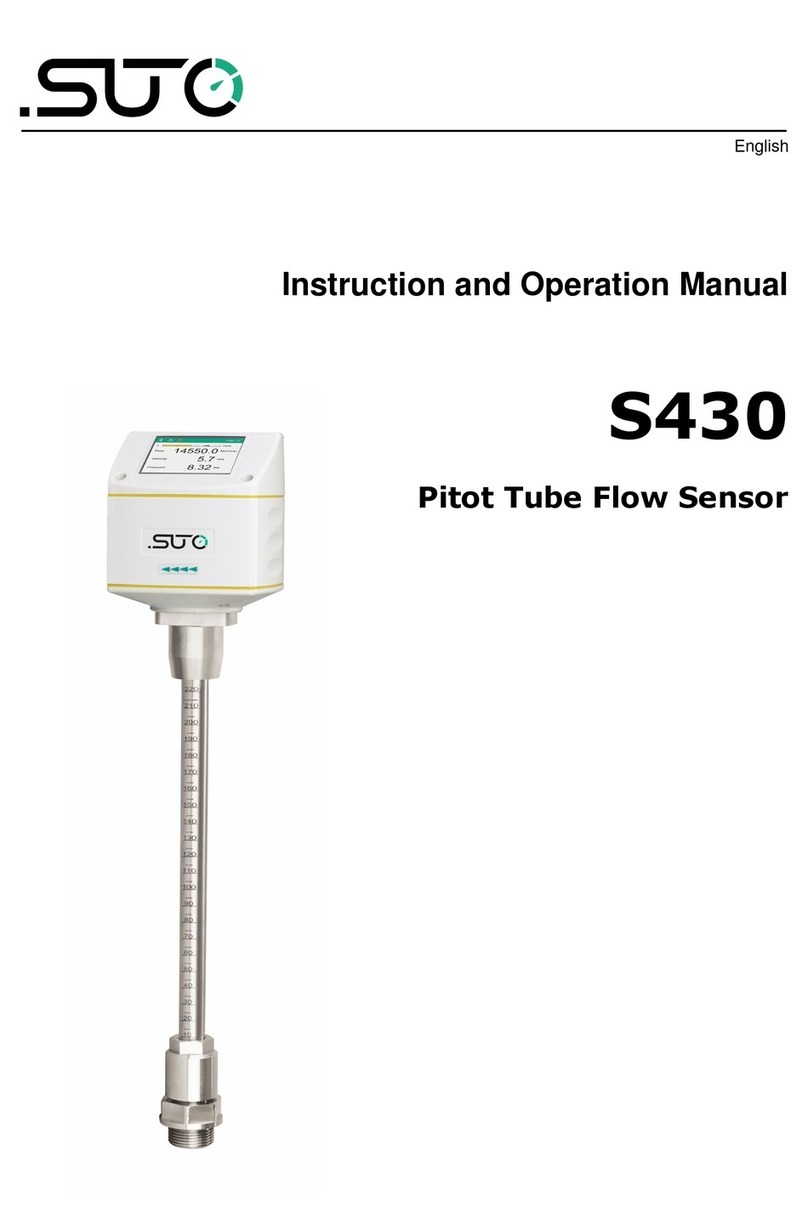
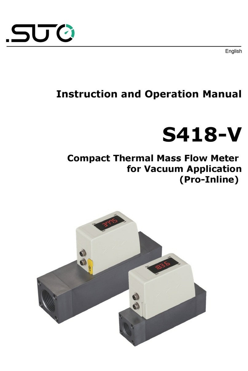
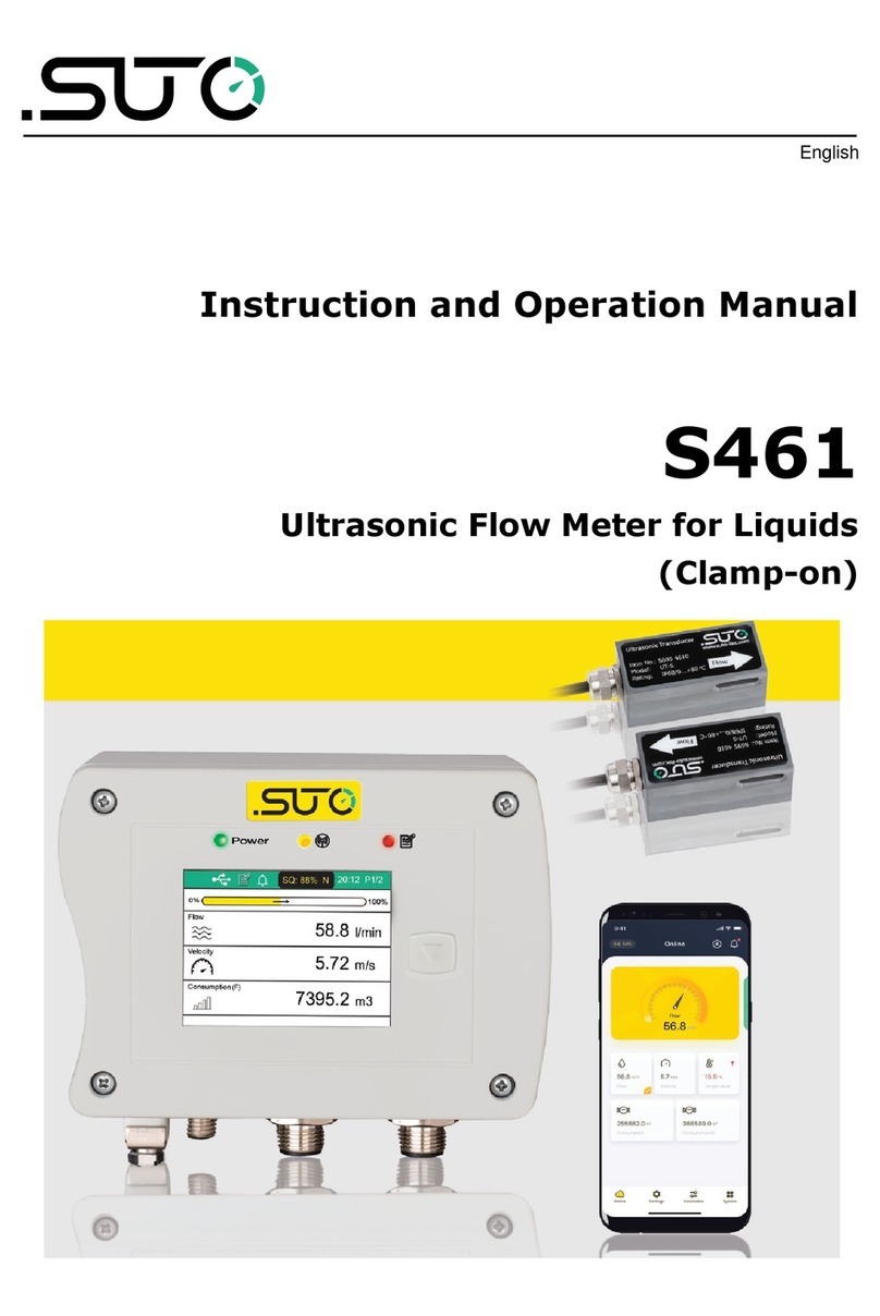
The 4C-F is an app that enables you to view measurement readings
and change settings for UTO flow meters through Android or iO
devices.
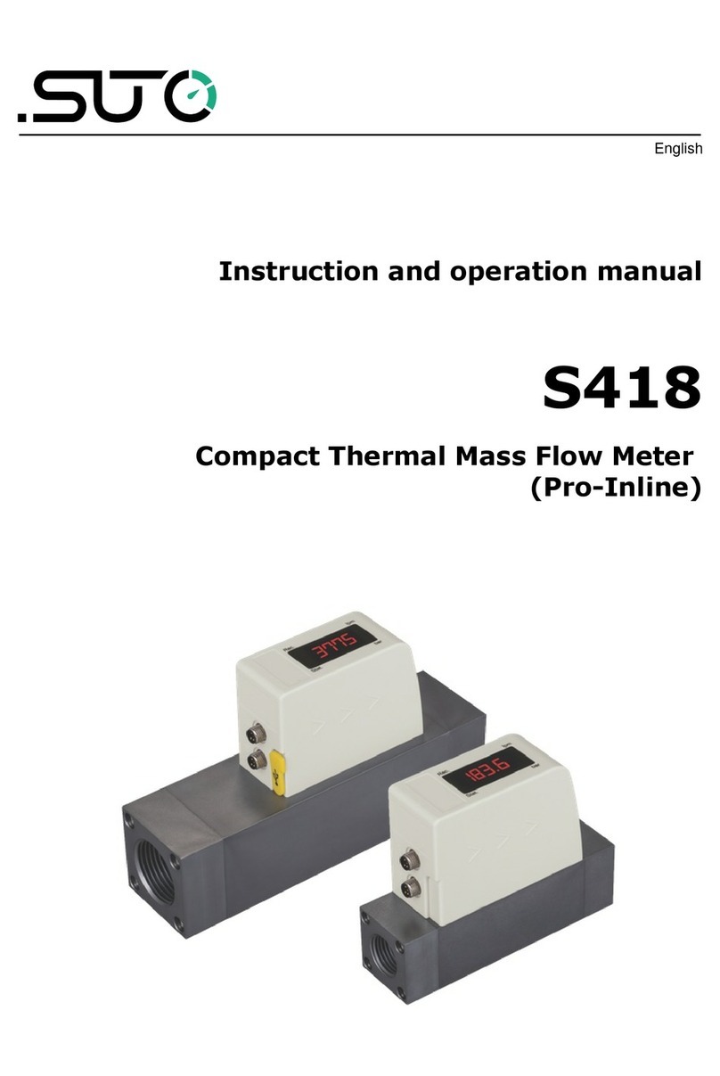
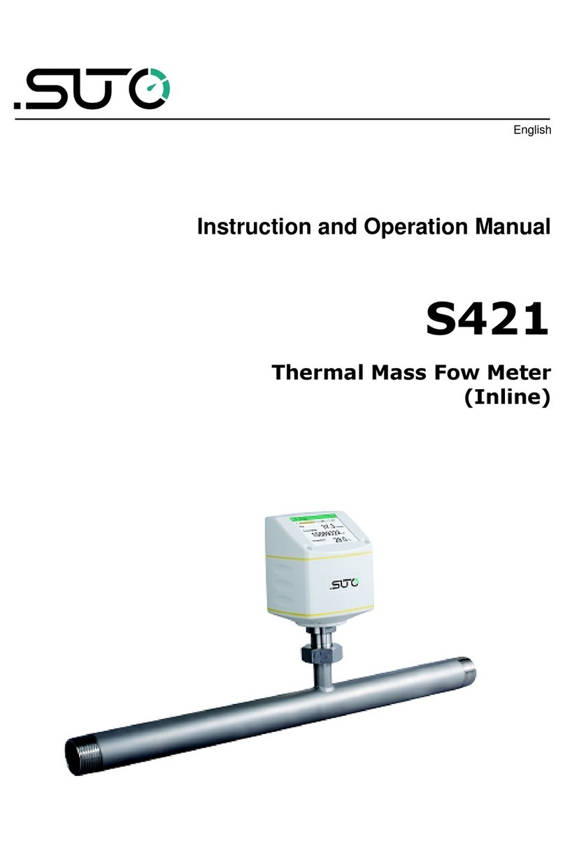
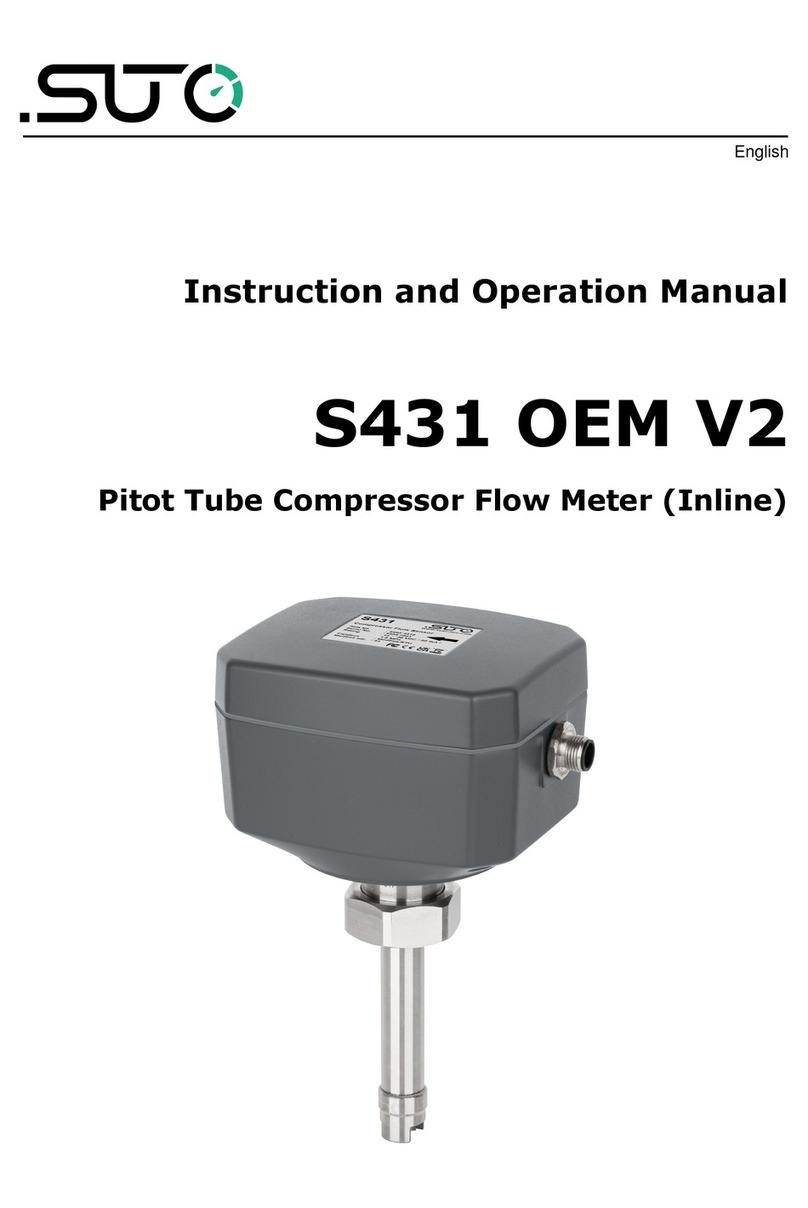
The 4C-F supports the following UTO flow meters:
•401, 402 and 421
•415 and 418
•418-V
•430
•431
2.1 System requirements
Ensure that your Android or iO devices meet the following
requirements:
•Android 7.0 or above versions installed
•iO 13 or above versions installed
•BLE4.0 and above supported (You can check the information with
the device vendor.)
Ensure that you have allowed the app to access the following
information:
•Location (Network-based approximate location and GP - and
Network-based precise location)
•Camera ( can the QR code)
•Pair with Bluetooth devices
•Device ID and call information (Read phone status and identity)
•Others (View network connections, View Wi-Fi connections, Access
Bluetooth settings, Change network connectivity, full network
access)
2.2 Operating requirements
The 4C-F can automatically detect a UTO flow meter when both of
the following requirements are satisfied:
•The UTO flow meter is powered on.
S4C-FS 5

2 Application
•The device is no more than 10-meter away from the flow meter
(within sight). Walls and metal enclosures will reduce the effective
distance!
3 Features
•mart phones and tablets applicable.
•Designed for service people to check sensor readings and change
sensor settings using Android or iO devices.
•Bluetooth integrated as the interface to communicate with the flow
meter.
•Multiple languages supported: English, German, Chinese, and
French.
4 Installation and connection
4.1 Installation
The Android-based 4C-F App file (*.APK) is available for download on
Google Play tore (play.google.com) and the UTO Website. (www.suto-
itec.com). The iO -based 4C-F App can be downloaded from Apple
App tore.
Use your mobile phone or tablet to download and install the application,
same as you do for any other apps.
After the 4C-F is launched on a device, the 4C-F automatically
detects powered-on flow meters within the valid distance of the device's
bluetooth signal.
When the 4C-F detects a flow meter for the first time, the 4C-F
has the Read-only access to the flow meter and can only view readings
and settings.
As shown in the following figure, a flow meter is detected with its name
and serial number displayed. The signal icon is shown in ED indicating
that the flow meter is Read-only. By clicking the flow meter name, you
trigger the 4C-F to connect with the flow meter. After the connection
is built, you are directed to the online view of the flow meter where you
can view the measurement data.
6 S4C-FS

4 Installation and connection
Note: The 4C-F can detect and connect to multiple flow meters. A
flow meter can connect to only one Android or iO device at a time.
4.2 Enable the configuration
Before using the 4C-F App to configure or calibrate flow meters, you
must obtain configuration permissions.
•For 401, 402, 421, 415, 418, 418-V, and 430, you can
scan the QR code of a specific flow meter to obtain its
configuration permission.
•For 431, you must register to obtain the configuration
permission.
4.2.1 Scan Q code
This function is applicable to flow meters supported by the 4C-F
except the 431.
To change settings of a flow meter, you must scan its QR code using the
4C-F App.
Preparation:
•Power on the flow meter.
•Obtain the QR code of the flow meter. The QR code is attached on
the side of the flow meter head or on the calibration certificate.
Following is an example of the QR code.
Steps:
1. Launch the S4C-FS on your phone.
The flow meters that are within the reach of the device's Bluetooth
S4C-FS 7

4 Installation and connection
are displayed on the screen, followed by a red signal icon.
2. Click the Scan Q Code button.
3. can the QR code on the flow meter's head or certificate.
After scanning the QR code, 4C-F saves the sensor information
to the Android or iO device, and the signal icon changes from
ED to G EEN, indicating that the flow meter is configurable
using the 4C-F .
Note: A G EEN hollow signal icon as shown in the following
figure indicates that the Bluetooth signal is weak. You can place
your device closer to the flow meter.
4.2.2 egister for configuring S431
This function is only applicable to the 431.
Before using the 4C-F App to configure or calibrate the 431, you
must register. Only registered users are able to modify settings. Please
get in touch with UTO service teams and provide the required
registration information.
8 S4C-FS

5 Menus
5.1 Online
The Online menu enables you to view the online measurement values
which are updated twice per second. Different flow meters have slightly
different measurement parameters as shown in the following table.
Flow meter Measurement
401 Flow, Consumption, Consumption[R]
402 Flow, Consumption, Consumption[R]
421 Flow, Consumption
430 Flow, Consumption, Consumption[R], Temperature, Velocity, Pressure
415 Flow, Consumption
418 Flow, Consumption, Pressure
418-V Flow, Consumption, Pressure
431 Flow, Consumption, Temperature, Velocity, Pressure
emarks:
The 418 shows the pressure only if the optional pressure sensor is
integrated.
5.2 Settings
The ettings menu enables you to change sensor settings and calibrate a
sensor. The ettings menu is enabled only when the 4C-F is completed
with scanning the QR code of the flow meter.
UTO flow meters provide various settings which influence the
performance and the features of the flow meters. Be careful when you
change the settings because they might affect the accuracy or the
overall performance. Contact UTO service team for information.
The following settings are available on UTO flow meters:
•Flow ettings
•Gas Type
•Units ettings
•Reference Conditions
•Factory ettings
•Counter ettings
•Output ettings
10 S4C-FS

5 Menus
•Calibrations
•Logger settings
For more information about the settings, see chapter 6 on page 11.
5.3 System
The System menu enables you to view or configure information of the
flow meter and 4C-F :
•ensor Info
•Language
•Version
For more information, see chapter 7 on page 19.
6 Settings
This chapter describes parameters in the ettings menu.
6.1 Flow settings
To configure settings related to flow measurement.
Parameter Description
Pipe diameter For all insertion type flow sensors, enter the correct inner
diameter of the pipe at the installation point.
For in-line flow meters, the diameter can not be changed.
Gas type elect a gas from the list of available gas types.
ome sensors have up to two real gas calibrations stored
(for example, CO2, CH4) which is indicated by the word
CAL behind the gas type.
Gas constant It is set through the selected gas type. Each gas type has
its own specific gas constants. When the gas type is
“other”, you have to input a gas constant.
Gas factor
Max flow, Min flow
These parameters are for information only and can not be
changed.
Flow type
(for 430 and 431 only)
430 and 431 support various flow types:
Flow tandard flow based on the reference
conditions that you set.
This is the most commonly used flow type,
which corresponds to the standard flow
measured with thermal mass flow meters.
Dry air flow Flow rate of dry air that is calculated based
on the relative inside-pipe humidity that you
S4C-FS 11

6 Settings
Parameter Description
set. 90% is the default. 430 is mainly used
in wet air flow behind compressors. This
selection enables you to view the dry flow
after the compressed air goes through a
dryer.
FAD Free Air Delivered referred back to the intake
air conditions that you set (temperature,
humidity, absolute pressure, and altitude).
Actual flow Actual volumetric flow rate at the system
pressure.
Installation
(for 430 and 431 only)
elect an installation type for 430:
•Center installation--The sensor tip is inserted to the
center of the pipe.
•100 mm insert depth--The sensor is only inserted
100 mm into the pipe. This installation type is used
in big pipe diameters where a center installation is
not feasible.
elect an an installation type for 431:
•DN50 … DN80: insertion depth is 25 mm.
•DN100 … DN900: insertion depth is 50 mm.
Cutoff Flow Threshold
(for 401, 402, 421,
431 only)
The cutoff flow threshold is a lower limit of the flow. All
measured flow that is lower than the threshold are set to
zero.
elect between 20 or 10 m/s (standard velocity) for 431.
6.2 Gas type
To select the gas type to be measured.
Flow meter Gas types
401 Air, CO2, O2, N2, N2O, Ar, Natural gas, CH4, Propane, Butane, Others
402 Air, CO2, O2, N2, N2O, Ar, Natural gas, CH4, Propane, Butane, Others
421 Air, CO2, O2, N2, N2O, Ar, Natural gas, CH4, Propane, Butane, Others
430 Air, CO2, O2, N2, N2O, Ar, Natural gas, CH4, Propane, Butane, Others
415 Air, N2
418 Air, CO2, O2, N2, N2O, Ar, Natural gas, CH4, Propane, Butane, Others
418-V Air
431 Wet/dry air, Others
6.3 Units settings
To set units for flow, pressure, temperature, and consumption.
12 S4C-FS

6 Settings
Available units are listed as follows based on the flow meter types.
6.3.1 Flow units
Flow meter Flow units
401 m3/h, m3/min, cfm, l/min, l/s, kg/h, kg/min, kg/s, Nm3/min, Nl/min,
Nm3/h, Nl/s, Ncfm
402 m3/h, m3/min, l/min, l/s, cfm, kg/h, kg/min, kg/s
421 m3/h, m3/min, cfm, l/min, l/s, kg/h, kg/min, kg/s, Nm3/min, Nl/min,
Nm3/h, Nl/s, Ncfm
430 m3/h, m3/min, cfm, l/min, l/s, kg/h, kg/min, kg/s, t/h, lb/h, Nm3/h,
Nm3/min, Ncfm, Nl/min, Nl/s
415 l/min, cfm, kg/h, m3/h, Nm3/h,Nl/min, Ncfm
418 l/min, cfm, kg/h, m3/h, Nm3/h,Nl/min, Ncfm
418-V l/min, cfm, kg/h, m3/h, Nm3/h,Nl/min, Ncfm
431 Volumetric flow: m³/h, m³/min, l/min, l/s, cfm
Mass flow: kg/h, kg/min, kg/s, t/h, lb/h
6.3.2 Pressure units
Flow meter Pressure units
401 N/A
402 N/A
421 N/A
430 bar, psi, MPa
415 N/A
418 bar, psi
418-V bar, psi
431 bar, psi, kPa, MPa
6.3.3 Temperature units
Flow meter Temperature units
401 N/A
402 N/A
421 N/A
430 °C, °F
415 N/A
418 N/A
S4C-FS 13

6 Settings
418-V N/A
431 °C, °F
6.3.4 Consumption units
Flow meter Consumption units
401 m3, l, kg, cf, Nm3, Nl, Ncf
402 m3, ft3 , kg
421 m3, l, kg, cf, Nm3, Nl, Ncf
430 m3, l, kg, cf, t, lb, Nm3, Nl, Ncf
415 m3, l, cf, kg, Nm3, Nl, Ncf
418 m3, l, cf, kg, Nm3, Nl, Ncf
418-V m3, l, cf, kg, Nm3, Nl, Ncf
431 m3, l, kg, ft3, t, lb
6.4 eference conditions
To configure “ tandard” or “Norm” conditions.
Reference conditions are used to calculate volumetric flow to so-called
“ tandard” or “Norm” conditions. This setting is important for gases
because the volume of a gas varies with pressure and temperature.
Parameter Values emark
tandard 1000 hPa, 20 °C elect this option when the gas to be measured is
compressed air.
Norm 1013.25 hPa, 0 °C elect this option when the gas to be measured is
nitrogen or another gas.
Customer
elect this option when it is necessary to convert
the flow at the compressor outlet to the flow in
the inlet suction state, that is, when the air
production capacity of the compressor needs to be
expressed by FAD (Free Air Delivery). Once
selected, the user has to manually enter the
reference temperature and reference pressure
values for the operating conditions.
6.5 Factory settings
These settings are ex-factory and not changeable by users.
Parameter emarks
Filter grade Enter a value between 0 … 127 as the filter grade. It's a damping of
the flow value which is used to stabilize the flow rate in systems
14 S4C-FS

6 Settings
where the flow is very unstable. A high value means a very high
damping (slow response).
Profile factor The profile factor is the ration between average flow in the pipe and
the centre flow.
6.6 Counter settings
To set the consumption counter to a new start value. ome flow sensors
work bi-directionally and therefore have a standard counter and a
reverse counter.
6.7 Output settings
There are various output options available depending on the flow meter
type and the ordered options. Here is an overview of available outputs:
Flow
meter
Output option
4 ... 20 mA
+pulse
Modbus
/ TU
Modbus
/TCP MBus Mbus
+Analog
Analog
compatible 400
401 Yes Yes Yes Yes Yes Yes
402 Yes Yes No Yes Yes Yes
421 Yes Yes Yes Yes Yes Yes
430 Yes Yes Yes Yes No No
415 Yes Yes No Yes No No
418 Yes Yes No Yes No No
418-V Yes Yes No Yes No No
431 Yes No No No No No
4 … 20 mA + pulse Description
caling:
4 mA
20 mA
Usually set to 0 flow
Usually set to maximum flow
Pulse per unit Drop list with the following three items:
- 1 pulse per consumption unit (default)
- 1 pulse per 10 consumption unit
- 1 pulse per 100 consumption unit
Modbus/ TU Description
Device address Each device must have a unique device address within
(1 ... 247) with the ex-factory value of 1.
Baudrate elect a baud rate from: 1200, 2400, 4800, 9600, 19200
(default), 38400, 57600, 115200
S4C-FS 15

6 Settings
Parity - None (default)
- Even
- Odd
top bit - 1 (default)
- 2
Note: All devices on the bus must have the same communication
parameters: baudrate, parity, start and stop bits.
Modbus/TCP Description
Ethernet
tatus
Cable tatus hows the status of the cable connection. Read only
Link peed hows the speed of the Ethernet link. Read only
Link tatus hows the status of the Ethernet link. Read only
TCP tatus hows the status of the TCP link.
This status identifies if a TCP client is in connection with
this flow meter, which works as a TCP server. Read only.
Ethernet
etting
DHCP hows the DHCP is in use or not.
- Yes (default)
- No: elected when you want to manually assign a fixed IP
address to this flow meter.
MAC hows the MAC address of this flow meter. Read only.
IPv4 - If the DHCP setting is Yes, shows the IP address that the
DHCP server assigns to this flow meter.
- If the DHCP setting is No, enter the fixed IP address that
is assigned to this flow meter.
ubnet
mask
- If the DHCP setting is Yes, shows the subnet mask that
the DHCP server provides to the flow meter.
- If the DHCP setting setting is No, enter the subnet mask
corresponding to the fixed IP address.
Gateway - If the DHCP setting to Yes, shows the IP address of the
default gateway that the DHCP server provides to the flow
meter.
- If the DHCP setting is No, enter the IP address of the
corresponding gateway.
Ethernet
Connection
etting
Mode hows TCP/Server, identifying that the flow meter works
as a TCP server. Read only
LocalPort hows the port number used for communication between
the server and client. Default: 502
If needed, you can change the port number. Range: 0 …
65535
16 S4C-FS

6 Settings
MBUS Description
Primary Address ettable from (1 ... 250)
econdary Address ettable and default is the product serial number.
Manufacturer Code Read only
M-BU Version Read only
Baudrate ettable from (300, 600, 1200, 2400, 4800, 9600)
Fabrication Number Read only
Response Delay (ms) Read only
Response Timeout (ms) Read only
Receive Timeout (ms) ettable from (0 … 65535)
6.8 Calibration
To perform calibration on a flow meter.
6.8.1 Calibration type
Flow meter Zero Flow Calibration Zero Pressure calibration
401 Y N/A
402 Y N/A
421 Y N/A
430 Y Y
415 Y N/A
418 Y N/A
418-V Y N/A
431 Y Y
6.8.2 Calibration parameters
Parameter Description
Apply User Calibration Needs to be activated to perform the calibration.
Compressor type
(for 431 only)
elect Load/Unload or V D.
For Load/Unload types, the calibration is offered at full
load (1 point). For V D compressors there are up to 5
calibration points available. It's recommended to select
them over the range of 10%...100%.
In general 3 points should be sufficient (10%, 50%,
90%).
Act. Flow This is the flow without the user calibration
as it is measured.
S4C-FS 17

6 Settings
Ref. Flow Manufacturer enters the flow measured by
the calibration stand in the factory.
Calibration points are sorted and user can
delete any of the calibration points.
6.9 Logger settings
When a flow meter comes with the data logger, you can use the 4C-F
to change logger-related settings of the flow meter.
Parameter emarks
Logger tatus To enable or disable the logger function.
tart Date & Time To view the start date and time for sampling.
top Date & Time To view the stop date and time for sampling.
Number of amples To view number of the data samples that the flow meter
has logged.
ampling Rate(mm:ss) To configure the sampling interval.
6.10 Upload settings
This function is only applicable to the 431.
The flow meter settings can be saved in the cloud server for a later
access in case the 431 need to be replaced in a service case. It is
recommended to use this function especially when has been tested and
calibrated together with the compressor in the factory or on the site
before a flow meter exchange.
6.11 Download settings
This function is only applicable to the 431.
In case the 431 has to be replaced the settings of the previous
installed 431 can be downloaded into the replacement unit. This is a
convenient way to ensure the same settings. User will be asked to enter
the serial number of the previous 431. In case the settings can be
found on the cloud server it will be downloaded into the new flow meter.
18 S4C-FS

7 System
7 System
This chapter lists information that you can view in the ystem menu
based on sensor types.
7.1 Sensor information
To view the sensor information.
S401 S402 S421 S430 S415 S418 S418-V S431
Device name Y Y Y Y Y Y Y Y
Item number Y Y Y Y Y Y Y Y
erial number Y Y Y Y Y Y Y Y
Production
date Y Y Y Y Y Y Y Y
Calibration
date Y Y Y Y Y Y Y Y
Option name Y Y Y Y Y Y Y Y
Bi-directional
measurement Y Y N/A Y N/A N/A N/A Y
Hardware
version Y Y Y Y Y Y Y Y
Firmware
version Y Y Y Y Y Y Y Y
7.2 Language
To set the language for 4C-F .
Language 语言 Sprache Langue
English 中文 Deutsch Francais
7.3 App version
To view the current version of the 4C-F .
S4C-FS 19

8 Maintenance
8 Maintenance
Make sure that Bluetooth always works well on your Android or iO
device.
Please check whether the latest version is installed on your device. For
Android device, you can download the latest version from Google Play
tore or the UTO Website. For iO device, download the App from
Apple App tore.
UTO iTEC GmbH
Grißheimer Weg 21
D-79423 Heitersheim
Germany
UTO iTEC (A IA) Co., Ltd.
Room 10, 6/F, Block B, Cambridge Plaza
188 an Wan Road, heung hui, N.T.
Hong Kong
Tel: +49 (0) 7634 50488 00
Email: [email protected]
Website: www.suto-itec.com
Tel: +852 2328 9782
Email: [email protected]
Website: www.suto-itec.com
UTO iTEC Inc.
5460 33rd t E
Grand Rapids, MI 49512
U A
Tel: +1 (616) 800-7886
Email: [email protected]
Website: www.suto-itec.com
All rights reserved © Modifications and errors reserved
S4C-FS_im_en_2023-1
20 S4C-FS
Table of contents
Other SUTO Measuring Instrument manuals