RhinorSD3/XD3 Electric Container Level Sensors
4
Part 1615748-01 E2019 Nordson Corporation
Set the Low, Empty and Follower-in-Drum Level Signals
Refer to Table 1. The Low and Empty Level signals are factory-set. If desired,
adjust the proximity sensor to change the factory settings.
CAUTION: To prevent damage to the equipment, personnel performing these
procedures must know how to safely operate the elevator control valve on the
Rhino SD2/SD3 unloader.
Perform the Change the Factory Settings procedure to change the factory settings.
Perform the Reset the Factory Settings procedure to reset the Low, Empty, and
Follower-in-Drum Level signals back to the factory settings.
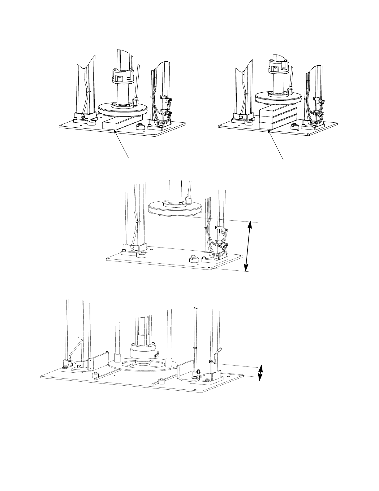
Table 1 Low and Empty Level Signal Factory Settings
Signal Setting
Low
5-Gal Follower Plate: 4.5 in. between the bottom of the
follower plate and the frame base plate rails.
55-Gal Follower Plate: 7.5 in. between the bottom of the
follower plate and the frame base plate rails.
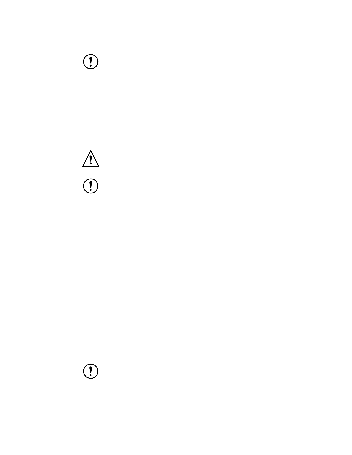
Empty
5-Gal Follower Plate: 1.5 in. between the bottom of the
follower plate and the frame base plate rails.
55-Gal Follower Plate: 1.5 in. between the bottom of the
follower plate and the frame base plate rails.
Mini-Tote: 2.375 in. between the bottom tip of the sensor and
the cylinder base.
Follower-in-
drum
5-Gal Follower Plate: ≥16.5 in. between the bottom of the
follower plate and the frame base plate.
NOTE: The follower-in-drum setting must be adjusted in the
field due to customer specific drum sizes.
55-Gal Follower Plate: ≥36.5 in. between the bottom of the
follower plate and the frame base plate.
NOTE: The follower-in-drum setting must be adjusted in the
field due to customer specific drum sizes.
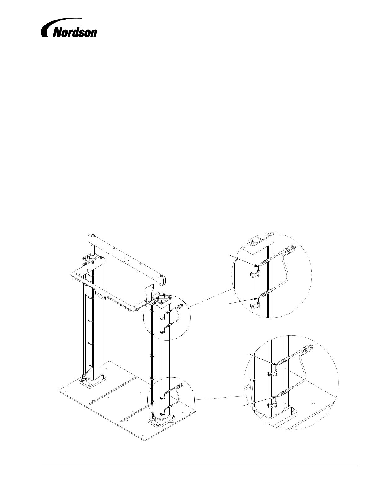
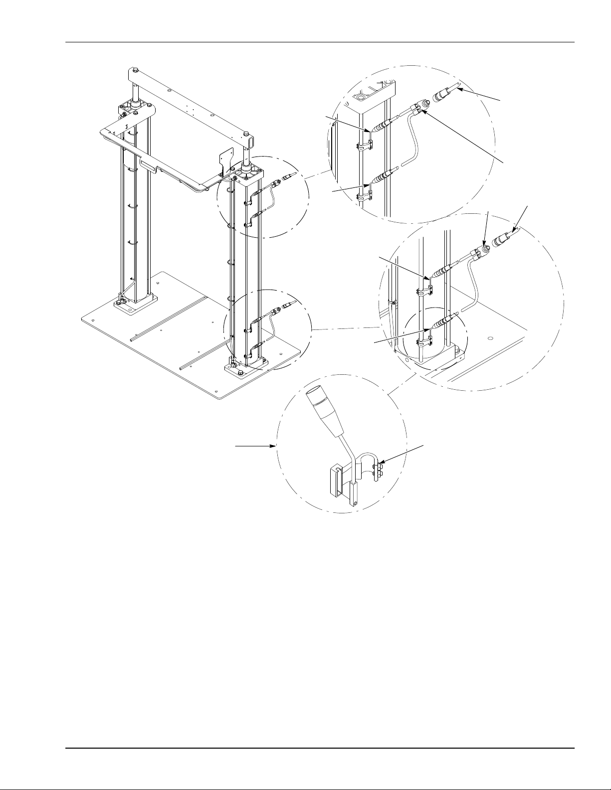
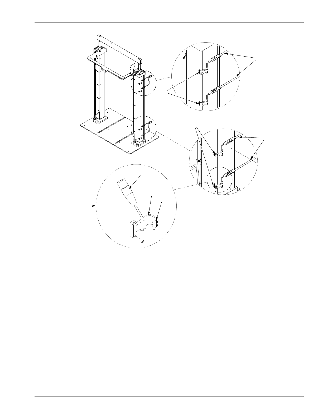
Change the Factory Settings
NOTE: The bottom lip on standard containers can vary and must be taken into
consideration when making adjustments to the magnetic sensors.
NOTE: Due to the variation in material containers, adjustment of the Drum Empty
sensor by the equipment end user is necessary to achieve minimal material waste.
NOTE: These steps are dependant on the system configuration. Not all
components, parts, or steps are applicable to all configurations.
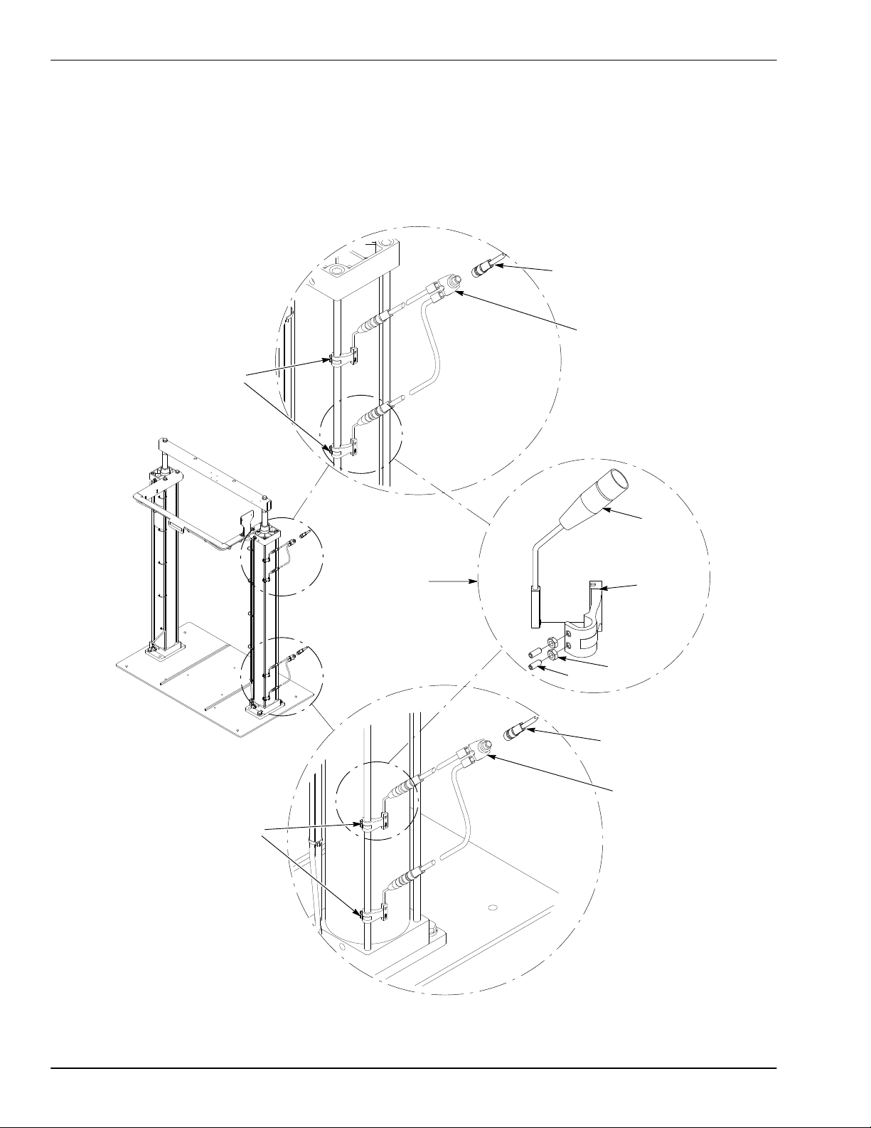
See Figure 2.
1. Loosen the set screws (9), move the magnetic sensor to the desired position,
and tighten the set screws (9).
2. Repeat step 1 for the remaining magnetic sensors if necessary.
3. Use the control valve to and lower the follower plate to test the
Follower-in-Drum,Low,and Empty Level signals.
4. Adjust as necessary.