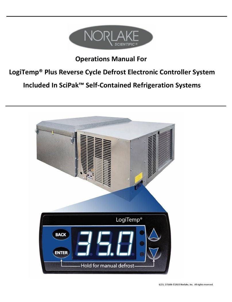
Norlake CP6 Series User manual

CP6, CP7, or CP8: Series Programmable Controller
Version 1.0
Page 1
NOR-LAKE SCIENTIFIC
CP6, CP7, CP8 SERIES PROGRAMMABLE CONTROLLER
TABLE OF CONTENTS PAGE
About the CP6, CP7, and CP8............................................................................................................................................................ 2
Sensor Location
Product Temperature........................................................................................................................................................... 2
Air Temperature.................................................................................................................................................................. 2
CP6, CP7, and CP8 controller layout, Operating buttons................................................................................................................... 4
Connection.......................................................................................................................................................................................... 5
LCD Display....................................................................................................................................................................................... 5
Starting up and operating the CP6, CP7, or CP8................................................................................................................................ 6
Room Set Points.................................................................................................................................................................. 7
Alarm Set Points.................................................................................................................................................................. 8
Ramp & Soak Programing................................................................................................................................................... 10
High level configuration...................................................................................................................................................... 12
Proportional Set-up.............................................................................................................................................................. 16
Lighting Set-up.................................................................................................................................................................... 18
Cooling Set-up..................................................................................................................................................................... 20
Heat Set-up.......................................................................................................................................................................... 22
Humidity Set-up.................................................................................................................................................................. 24
Digital Inputs....................................................................................................................................................................... 26
Sensor calibration offset...................................................................................................................................................... 28
Manual system control ........................................................................................................................................................ 29
Maintenance run times ........................................................................................................................................................ 31
Alarm silencing, setting, resetting and clearing................................................................................................................... 32
Hardware technical information
Mounting Control Panel...................................................................................................................................................... 34
Main board layout .............................................................................................................................................................. 35
Power Supply ..................................................................................................................................................................... 37
Connecting inputs .............................................................................................................................................................. 38
Connecting outputs ............................................................................................................................................................. 41
Technical specifications ..................................................................................................................................................... 42
Replacement parts............................................................................................................................................................... 45
05/03 113470
Nor-Lake Inc.
Nor-Lake Scientific
1-800-388-5253
Ver. Date : 00/00/00

CP6, CP7, or CP8: Series Programmable Controller
Version 1.0
Page 2
ABOUT THE CP6, CP7, AND CP8
The CP6, CP7, and CP8 are a new programmable controller based on a 16-bit microprocessor designed for
Nor-Lake Inc. Scientific control panels. The control panels are made up of a microprocessor-based MAIN
BOARD equipped with a set of terminals used to connect the board to the controlled devices (i.e.: valves,
lights, fans, and humidification, alarm triggers). The program and the parameters are saved permanently in
the FLASH memory, preventing data loss in the event of power failure (with-out requiring a backup battery).
The control panel also includes a microprocessor-based TERMINAL unit complete with display, keypad and
led indicators allowing you to easily set the main control parameters (set-points, bands, alarm thresholds) and
carry out the main working operations (on/off, displaying controlled variables). Connection between the
terminal unit and main board is necessary only when programming the control panels’ basic parameters.
The basic sequence of operation is:
CP6 - on/off control using a pump down solenoid
CP7 and CP8 - cooling and heating using hot gas bypass using either a solenoid or by a proportional
modulating electronic valve
CP8 - activate the humidifier as needed when the humidity falls below the set point
CP8 - activate the dehumidifier as needed when the humidity exceeds set point
Dual mode defrost timer; Time initiated –Time terminated or Time initiated –Temperature terminated
In addition to the basic sequence of operation, optional features are available:
two display options using LED and Graphical displays
networking to a central command computer, or to an existing building automation system
monitor the sensors, compressors and heaters for failure. On a sensor failure, the applicable systems are
disabled. On a compressor failure by low or high pressure, the compressor is locked out and other
compressors substituted. On a heater failure the heaters are locked out, but automatically reset.
multi channels of on/off light control
day/night settings for Temperature and Humidity
redundant system operation of two units with automatic crossover
The CP6, CP7, and CP8’s are truly one of the most powerful and flexible controllers available today.
SENSOR LOCATION
The location of the sensors is very important. All sensors should be positioned away from electromagnetic
noise. The product temperature sensor should be immersed in glycerin or other suitable medium that
thermally simulates the product. The glycerin well/product sensor is normally mounted on the wall near the
door and should be mounted at a height that will best reflect the product storage height, normally 40” above
the floor. For optimum temperature control the air temperature sensor should be mounted at a location, out of
the direct discharge of the evaporator coil, that best reflects the median temperature of the room. If the sensor
lead is not long enough, the lead may be extended using 18 gauge wire. The humidity sensor (CP8 Series)
should be mounted at a height that will best reflect the product storage height, normally 40” above the floor.
It is critical that the humidity sensor is located out of any direct air stream or discharge from devices;
evaporators, door openings, humidifiers, dehumidifiers, heat from lights, etc. If the sensor lead is not long
enough, the lead may be extended using 18 gauge wire. After the sensors are mounted, seal the hole in the
wall where the leads were fed with silicone sealant to prevent airflow through the hole.

CP6, CP7, or CP8: Series Programmable Controller
Version 1.0
Page 3
FRONT PANEL VIEW
Figure 1
Function of the Polycarbonate covered buttons with LED’s
Returns you to the main display from anywhere in the program
Displays the maintenance information of each device (working hours)
Allows you to access the displays concerning the printer (optional)
Allows you manual control of all systems (resets to AUTO on power off)
Nor-Lake Inc.
Nor-Lake Scientific
1-800-388-5253
Ver.Date :00/00/00

CP6, CP7, or CP8: Series Programmable Controller
Version 1.0
Page 4
Real time clock settings, night/day settings, dual channel light settings(optional)
Allows you to set the controlling set points
Allows you to set the main working parameters (startup delays, redundancy, defrost settings, door
heater adjustments, etc.)
This screen gives product version number and information to the user.
Aux 1 allows you to enter digital input setup
Aux 2 allows you to enter control offsets for sensors (analog)
PLASTIC BUTTON FUNCTIONS
1. On/Off: turns the system on and off. This will include the room lights, outlets, refrigeration, heating, and
humidity control. The green LED lit behind the button indicates that the unit is ON. WARNING:
DISCONNECT ALL SYSTEM POWER BEFORE SERVICING ANY EQUIPMENT!
2. Alarm: by pressing this button you can display the active alarms, reset them manually or silence the
buzzer. When the red LED indicator lights up, at least one alarm condition has occurred.
3. Up arrow: moves upward through the program windows and increases the values of the control parameter
when the cursor is in a parameter field (no backlight).
4. Down arrow: moves downward through the program windows and decreases the values of the control
parameter when the cursor is in a parameter field (no backlight).
5. Enter: moves the cursor between parameter fields and confirms the set data. The button is backlit
(yellow light) and indicates that the unit is being powered.

CP6, CP7, or CP8: Series Programmable Controller
Version 1.0
Page 5
DISPLAY
liquid crystal display (LCD)
LCD Display
Figure 2
Features
number of lines: 4
number of characters per line: 20
character height: 5 mm
no LED indicator
CONNECTION
The display unit is connected to the control board by a 6-wire standard phone cord of up to 1,000 feet in
length.
NOTE: A short, special phone cord is supplied with the controller. Connect a standard 6-wire phone cord
expansion to the end of this cord. DO NOT REPLACE THE SPECIAL CORD as this cord is
reversed from the normal phone cord. The control will not work if only a standard phone cord is
used.
Nor-Lake Inc.
Nor-Lake Scientific
1-800-388-5253
Ver. Date : 00/00/00

CP6, CP7, or CP8: Series Programmable Controller
Version 1.0
Page 6
STARTING UP AND OPERATING THE NOR-LAKE CONTROL
On first power up of the Nor- Lake Inc. unit, the CP6, CP7, or CP8 display will light and display the opening
screen:
Notes: 1. After 1 minute the screen will default to the system status screen.
2. To move to the next screen the cursor has to be positioned in the upper left-hand corner
of the current screen.
3. The ENTER key will move the cursor in the current screen.
KEY:MENU
Pressing the MENU key will display the following screen. The MENU screens are display screens only to
change set points the values must be entered at the corresponding screens. To view screens progressively,
use the down arrow key.
MENU 1
Displays product temperatures and the room humidity. Humidity will only be displayed if the
humidifier or dehumidifier control has been enabled. The lower line displays a second product
temperature.
Note: Product 2 temperature will only be displayed if an additional sensor is installed and the
sensor is enabled on System Setup 3.
MENU 2
Displays system demands. The bottom line is used to show the status of the compressors and
could show the conditions:
C1/C2:ON when air temperature is above the room temperature set point.
C1/C2:OFF when air temperature is at or bellow the room temperature set point.
HT1/HT2:ON when the auxiliary heaters are on.
C1/C2:DF when the system is in a defrost cycle.
C1/C2:ERR when the compressor alarm is active.
Note: C1 is for compressor #1. C2 is for compressor #2 and will only be displayed for systems
equipped with two compressors.
Nor-Lake Inc.
Hudson, WI
Parts and Service
1-800-388-5253
SYSTEM STATUS
PRODUCT: 000.0C
Humidity: 000%RH
PRODUCT 2: 000.0C
Air Temp: 000.0C
Cool:000% Deh:000%
Heat:000% Hum:000%
C1:OFF C2:OFF

CP6, CP7, or CP8: Series Programmable Controller
Version 1.0
Page 7
MENU 3
Displays the current set points of the system. The date and time will only be displayed if a RTC
(real time clock) card is installed in the controller. The humidity and lighting set points will only
be displayed if each one is enabled.
KEY:SET
Note: If the password protection is used the following screen will be displayed before allowing access to the
SET POINTS screens. On initial start up there is no password protection, the passwords are set in the
PARAMETERS group. If no password protection is used the “ENTER PASSWORD” screen will not
be displayed.
Press the ENTER key to move the cursor to the four-digit password. Use the Up or Down Arrow key to
increase or decrease the number. When the correct password is displayed press the ENTER key to enter the
password. If the correct password was entered the corresponding screen will be displayed. If a wrong
password was entered “WRONG PASSWORD” will be displayed on the bottom line. The password can be
re-entered or press the MENU key to return to the System Status screen.
SET POINTS: Screen 1
Note: The schedule information will only be visable if a RTC is installed. If the schedule is enabled the
temperature will be set through the ramp and soak schedule. To disable the ramp and soak schedule
press the ENTER key to move the cursor to the schedule field. Use the Up or Down Arrow key to
disable the schedule. Press the ENTER key and the cursor will move to the upper left hand corner and
the set point will be visible. A full explanation of the ramp and soak schedule follows.
ENTER PASSWORD
0000
WRONG PASSWORD
SUN 00/00/00 00:00
Current Set points
Temp:000.0C
Hum:000.0% Lts:000%
Room Set Points 1
Temperature> 04.0C
SCHEDULE >DISABLED
Goto Schedule >

CP6, CP7, or CP8: Series Programmable Controller
Version 1.0
Page 8
SET POINTS: Screen 2
Note: The following screen will only be visible if the humidity is enabled in the Parameter section.
Press the ENTER key to move the cursor to the set point data field. Use the Up or Down Arrow
key to increase or decrease the number. When the correct set point is displayed press the ENTER
key to enter the set point, the cursor will move to the upper left hand corner. Press the Up or Down
Arrow key to scroll through the other screens or press the MENU key to return to the System Status
screen.
SET POINTS: Screen 3
Note: The following screen will only be visible if the Lights are enabled in the Parameter section.
Press the ENTER key to move the cursor to the set point data field. Use the Up or Down Arrow
key to increase or decrease the number. When the correct set point is displayed press the ENTER
key to enter the set point, the cursor will move to the upper left hand corner. Press the Up or
Down Arrow key to scroll through the other screens or press the MENU key to return to the
System Status screen.
SET POINTS: Screen 4
Press the ENTER key to move the cursor to the set point data field. Use the Up or Down Arrow
key to increase or decrease the number. When the correct value is displayed press the ENTER key
to enter the set point, the cursor will move to the next data field. Press the ENTER key to move
the cursor to the upper left hand corner and the Up or Down Arrow key to scroll to the next set
point screen or press the MENU key to return to the System Status screen.
Note: The High and Low Air Temperature Alarms provide an early warning prior to the product temperature
alarm. They should be set to allow the normal rise and fall of the air temperature during normal
operation. High ambient temperature and heavy door use may require a longer Alarm Delay. The
ALARM DELAY is the amount of time in seconds that the temperature must be above or below the
alarm set point for the alarm to activate.
Room Set Points 2
Humidity>050.0%
R.H.
Room Set Points 3
Lights>100%
Room Air
Temperature
High Alarm>000.0°C
Low Alarm>000.0°C
Alarm Delay> 000
sec

CP6, CP7, or CP8: Series Programmable Controller
Version 1.0
Page 9
SET POINTS: Screen 5
Press the ENTER key to move the cursor to the set point data field. Use the Up or Down Arrow
key to increase or decrease the number. When the correct value is displayed press the ENTER key
to enter the set point, the cursor will move to the next data field. Press the ENTER key to move
the cursor to the upper left hand corner and the Up or Down Arrow key to scroll to the next set
point screen or press the MENU key to return to the System Status screen.
SET POINTS: Screen 6
Note: This setting will be applicable to rooms equipped with two Product temperature sensors.
Press the ENTER key to move the cursor to the set point data field. Use the Up or Down Arrow
key to increase or decrease the number. When the correct value is displayed press the ENTER key
to enter the set point, the cursor will move to the next data field. Press the ENTER key to move
the cursor to the upper left hand corner and the Up or Down Arrow key to scroll to the next set
point screen or press the MENU key to return to the System Status screen.
SET POINTS: Screen 7
Note: The following screen will only be visible if the Humidity is enabled in the Parameter section.
Press the ENTER key to move the cursor to the set point data field. Use the Up or Down Arrow
key to increase or decrease the number. When the correct value is displayed press the ENTER key
to enter the set point, the cursor will move to the next data field. Press the ENTER key to move
the cursor to the upper left hand corner and the Up or Down Arrow key to scroll to the next set
point screen or press the MENU key to return to the System Status screen.
Product Temperature
High Alarm>000.0°C
Low Alarm>000.0°C
Alarm Delay 000 sec
Humidity Alarms
High Alarm>000.0°C
Low Alarm>000.0°C
Alarm Delay 000 sec
Product 2 Temp.
High Alarm>000.0°C
Low Alarm>000.0°C
Alarm Delay 000 sec

CP6, CP7, or CP8: Series Programmable Controller
Version 1.0
Page 10
RAMP AND SOAK SCHEDULE
SET POINTS: Screen 1
Press the ENT key until the cursor moves to the schedule field. Use the Up or Down arrow key to
enable the schedule. Press the ENT key and the first of 21 Ramp and Soak screens will be displayed.
RAMP & SOAK
Weekly/Daily:
Daily, Mon, Tues, Wed,
Thur, Fri, Sat, Sun.
Time
Temperature Set Point
Humidity Set Point
Lighting Set Point
Ramp/Hold:
Ramp Set Point or Hold Set Point
Press the ENT key and the cursor moves to the Day of the Week/Daily field. Use the Up or Down
arrow key to select daily or the day of the week the schedule is to begin. Press the ENT key and the
cursor will move to the time field. Use the Up or Down arrow key to enter the desired time to change
the set points. Press the ENT key and the cursor will move to the temperature set point field. Use the
Up or Down arrow key to enter the desired temperature set point. Press the ENT key and the cursor
will move to the humidity set point field (if activated). Use the Up or Down arrow key to enter the
desired humidity set point. Press the ENT key and the cursor will move to the light set point field (if
activated). Use the Up or Down arrow key to enter the desired lighting set point.
Press the ENT key and the cursor will move to the Ramp / Hold field. Use the Up or Down arrow key
to select to Ramp the set point to the next scheduled set point or to Hold the set point until the next
scheduled set point. Press the ENT key and the cursor will move to the upper left hand corner. Press
the Down arrow key to go to the next schedule.
Note: If Daily is selected on the Program #1 screen programs 1 through 21 will repeat each day. Any
unused programs will have to be turned off.
Room Set Points 1
Temperature> 04.0C
SCHEDULE >DISABLED
Goto Schedule >
Program Mon
12:01 04.0°C
50.0%RH Lights:100%
Ramp Set Point

CP6, CP7, or CP8: Series Programmable Controller
Version 1.0
Page 11
Ramp and Soak Example
The following example will ramp from 4.0°C to 10.0°C every Monday from 06:00 to 12:00. The
temperature will remain at 10.0°C until Wednesday at 06:00 when it will begin ramping the set point
down to 4.0°C at 12:00 Wednesday. The set point will remain at 4.0°C until Friday at 06:00 when it
will begin ramping the set point up to 10.0°C at 12:00 Friday. The set point will remain at 10.0°C until
Sunday at 06:00 when it will begin ramping the set point down to 4.0°C at 12:00 Sunday. The
temperature set point will remain at 4.0°C until the schedule repeats Monday at 06:00.
It is recommended to fill out the Ramp and Soak worksheet on page 47 of this manual before
programming the ramp and soak functions of the controller.
Program #
Daily/Weekly
Time
Temp.
Humidity
Lights
Ramp/Hold
1
Mon.
6:00
4.0°C
N/A
N/A
Ramp
2
Mon.
12:00
10.0°C
N/A
N/A
Hold
3
Wed.
6:00
10.0°C
N/A
N/A
Ramp
4
Wed.
12:00
4.0°C
N/A
N/A
Hold
5
Fri.
06:00
4.0°C
N/A
N/A
Ramp
6
Fri.
12:00
10.0°C
N/A
N/A
Hold
7
Sun.
06:00
10.0°C
N/A
N/A
Ramp
8
Sun.
12:00
4.0°C
N/A
N/A
Hold
9
Off
N/A
N/A
10
Off
N/A
N/A
11
Off
N/A
N/A
12
Off
N/A
N/A
13
Off
N/A
N/A
14
Off
N/A
N/A
15
Off
N/A
N/A
16
Off
N/A
N/A
17
Off
N/A
N/A
18
Off
N/A
N/A
19
Off
N/A
N/A
20
Off
N/A
N/A
21
Off
N/A
N/A

CP6, CP7, or CP8: Series Programmable Controller
Version 1.0
Page 12
KEY:PROG.
The PROG key is used to configure the system. Proportional set-up and light control are also
set here if present on the system. Press the PROG key, then press the ENTER key to move to the desired
field. Press the ARROW DOWN key to enter the desired set up function.
KEY:PROG AND SELECTING THE CONFIG SETUP ITEM
Note: If the password protection is used the following screen will be displayed before allowing access to the
CONFIG SET POINTS screens. On initial start up there is no password protection the passwords are
set in the PARAMETERS group. If no password protection is used the “ENTER PASSWORD” screen
will not be displayed.
Press the ENTER key to move the cursor to the four-digit password. Use the Up or Down Arrow key to
increase or decrease the number. When the correct password is displayed press the ENTER key to enter the
password. If the correct password was entered the corresponding screen will be displayed. If a wrong
password was entered “WRONG PASSWORD” will be displayed on the bottom line. The password can be
re-entered or press the MENU key to return to the System Status screen.
CONFIG 1
Press the ENTER key to move the cursor to the set point data field. Use the Up or Down Arrow
key to increase or decrease the number. When the correct value is displayed press the ENTER key
to enter the set point, the cursor will move to the next data field. Press the ENTER key to move
the cursor to the upper left hand corner and the Up or Down Arrow key to scroll to the next set
point screen or press the MENU key to return to the System Status screen.
Note: The System Delay is the initial delay of the system on power up. The door alarm delay is
the amount of time the door can remain open before the Door Ajar Alarm is activated.
Technician Menu
Config Set. . . . .>
Proportional Set up>
Lights On/Off Set..>
System Setup 1
System delay>000sec
Door al delay>00min
ENTER PASSWORD
0000
WRONG PASSWORD

CP6, CP7, or CP8: Series Programmable Controller
Version 1.0
Page 13
CONFIG 2
Press the ENTER key to move the cursor to the set point data field. Use the Up or Down Arrow
key to toggle between ON or OFF. When the correct value is displayed press the ENTER key to
enter the set point, the cursor will move to the next data field. Press the ENTER key to move the
cursor to the upper left hand corner and the Up or Down Arrow key to scroll to the next set point
screen or press the MENU key to return to the System Status screen.
Note: The Alarm Ring Back feature is the amount of time, in minutes, that the buzzer will be silent
after an alarm has been acknowledged and remains active.
CONFIG 3
Press the ENTER key to move the cursor to the set point data field. Use the Up or Down Arrow
key to toggle between DISABLED or ENABLED. When the correct value is displayed press the
ENTER key to enter the set point, the cursor will move to the next data field. Press the ENTER
key to move the cursor to the upper left hand corner and the Up or Down Arrow key to scroll to the
next set point screen or press the MENU key to return to the System Status screen.
Note: This screen enables or disables the second product sensor. A sensor must be connected to
the product 2 input of the control board or a sensor failure alarm will activate.
CONFIG 4
Press the ENTER key to move the cursor to the set point data field. Use the Up or Down Arrow
key to increase or decrease the number. When the correct value is displayed press the ENTER key
to enter the set point, the cursor will move to the next data field. Press the ENTER key to move
the cursor to the upper left hand corner and the Up or Down Arrow key to scroll to the next set
point screen or press the MENU key to return to the System Status screen.
System Setup 2
Alarm Buzzer>OFF
Ring Back >20 MIN
System Setup 3
PRODUCT 2 SENSOR
DISABLED
System Setup 4
Defrost Schedule
1 00:00 3 00:00
2 00:00 4 00:00

CP6, CP7, or CP8: Series Programmable Controller
Version 1.0
Page 14
Real time defrost schedule. The RTC defrost is enabled on Setup Screen 6 in the Factory Setup
Screens. Selecting the (RTC) will allow for real time based defrosting, instead of run time defrost
when the SYS Option is selected. The system may be programmed for 4 defrost cycles every 24
hour period.
CONFIG 5
Press the ENTER key to move the cursor to the set point data field. Use the Up or Down Arrow
key to toggle between Centigrade and Fahrenheit. When the correct value is displayed press the
ENTER key to enter the set point, the cursor will move to the next data field. Press the ENTER
key to move the cursor to the upper left hand corner and the Up or Down Arrow key to scroll to the
next set point screen or press the MENU key to return to the System Status screen.
Note: If the user changes temperature units, all set points and bands
must be verified in terms of the new unit. If the parameters have
changed, then they must be re-entered.
CONFIG 6
Press the ENTER key to move the cursor to the set point data field. Use the Up or Down Arrow
key to toggle between DISABLED or ENABLED. When the correct value is displayed press the
ENTER key to enter the set point, the cursor will move to the next data field. Press the ENTER
key to move the cursor to the upper left hand corner and the Up or Down Arrow key to scroll to the
next set point screen or press the MENU key to return to the System Status screen.
Communications set-up.
Protocol: NLSUP RS485,NLSUP RS232,MODBUS
Baud Rate: 1200,2400,4800,9600,19200
Ident Number: 0 to 200
System Setup 5
Units>Centigrade
Change set points
To Fahrenheit
System Setup 6
Protocol> NLSUP RS485
BAUD RATE> 1200
INDENT NUMBER> 000

CP6, CP7, or CP8: Series Programmable Controller
Version 1.0
Page 15
CONFIG 7
Press the ENTER key to move the cursor to the set point data field. Use the Up or Down Arrow
key to increase or decrease the value. When the correct value is displayed press the ENTER key to
enter the set point, the cursor will move to the next data field. Press the ENTER key to move the
cursor to the upper left hand corner and the Up or Down Arrow key to scroll to the next set point
screen or press the MENU key to return to the System Status screen.
Note: The use and selection of Password is RECOMMENDED to protect the system from intentional or
inadvertent tampering. If passwords are not utilized, there will not be password prompting during
programming. This is very dangerous as the factory settings, designed to protect personnel and property, are
left exposed to tampering.
CONFIG 8
Press the ENTER key to move the cursor to the set point data field. Use the Up or Down Arrow
key to increase or decrease the value. When the correct value is displayed press the ENTER key to
enter the set point, the cursor will move to the next data field. Press the ENTER key to move the
cursor to the upper left hand corner and the Up or Down Arrow key to scroll to the next set point
screen or press the MENU key to return to the System Status screen.
Note: The exhaust fan will operate only when the room set point is above the low limit and below the high
limit.
System Setup 7
Passwords
Level 1>0000 SetPts
Level 2>0000 Config
System Setup 8
Exhaust Fan
Low Limit> 00.0°C
High Limit> 00.0°C

CP6, CP7, or CP8: Series Programmable Controller
Version 1.0
Page 16
KEY:PROG AND SELECTING THE PROPORTIONAL SETUP
Note: If the password protection is used the following screen will be displayed before allowing access to the
Proportional Set Up screens. On initial start up there is no password protection the passwords are set
in the PARAMETERS group. If no password protection is used the “ENTER PASSWORD” screen
will not be displayed.
Press the ENTER key to move the cursor to the four-digit password. Use the Up or Down Arrow
key to increase or decrease the number. When the correct password is displayed press the ENTER
key to enter the password. If the correct password was entered the corresponding screen will be
displayed. If a wrong password was entered “WRONG PASSWORD” will be displayed on the
bottom line. The password can be re-entered or press the MENU key to return to the System
Status screen.
PROP 1
Press the ENTER key to move the cursor to the set point data field. Use the Up or Down Arrow
key to increase or decrease the value. When the correct value is displayed press the ENTER key to
enter the set point, the cursor will move to the next data field. Press the ENTER key to move the
cursor to the upper left hand corner and the Up or Down Arrow key to scroll to the next set point
screen or press the MENU key to return to the System Status screen.
TYPE is set to either P(PROPORTIONAL) or PI (PROP + INTEGRAL). If PROP + INTEGRAL
control is chosen, the user must enter the INTEGRATION TIME> as well. Also, enter the
proportional band for control. Proportional + integral control works as follows: When the actual
reading is away from the set point for more than the integration time, the proportional signal
strength is increased to drive the temperature back to set point.
Control setpoints 1
Bands
Type Int HT CL
Temp>P 000s 00 00C
ENTER PASSWORD
0000
WRONG PASSWORD

CP6, CP7, or CP8: Series Programmable Controller
Version 1.0
Page 17
PROP 2
Press the ENTER key to move the cursor to the set point data field. Use the Up or Down Arrow
key to increase or decrease the value. When the correct value is displayed press the ENTER key to
enter the set point, the cursor will move to the next data field. Press the ENTER key to move the
cursor to the upper left hand corner and the Up or Down Arrow key to scroll to the next set point
screen or press the MENU key to return to the System Status screen.
Enter the start and end points for the demand, which is based on the temperature set point and
proportional band. The Start set point is the minimum proportional signal and the End set point is
the maximum proportional signal. As the actual reading moves from the set point within the
proportional band the signal will change proportionally to bring the actual reading back to the set
point.
PROP 3
Press the ENTER key to move the cursor to the set point data field. Use the Up or Down Arrow
key to increase or decrease the value. When the correct value is displayed press the ENTER key to
enter the set point, the cursor will move to the next data field. Press the ENTER key to move the
cursor to the upper left hand corner and the Up or Down Arrow key to scroll to the next set point
screen or press the MENU key to return to the System Status screen.
TYPE is set to either P (PROPORTIONAL) or PI ( PROP + INTEGRAL). If PROP + INTEGRAL
control is chosen, the user must enter the INTEGRATION TIME> as well. Also, enter the
proportional band for control. Proportional + integral control works as follows: When the actual
reading is away from the set point for more than the integration time, the proportional signal
strength is increased to help drive it back to set point.
Control setpoints 2
Ramps Start End
Cooling> 000% 100%
Heating> 000% 000%
Control setpoints 1
Bands
Type Int HU DH
Temp>P 000s 00 00%

CP6, CP7, or CP8: Series Programmable Controller
Version 1.0
Page 18
PROP 4
Press the ENTER key to move the cursor to the set point data field. Use the Up or Down Arrow key
to increase or decrease the value. When the correct value is displayed press the ENTER key to enter
the set point, the cursor will move to the next data field. Press the ENTER key to move the cursor to
the upper left hand corner and the Up or Down Arrow key to scroll to the next set point screen or
press the MENU key to return to the System Status screen.
SET 4: Enter the start and end points for the demand which is based on the relative humidity set
point and proportional band. The Start set point is the minimum proportional signal and the End
set point is the maximum proportional signal. As the actual reading moves from the set point
within the proportional band the signal will change proportionally to bring the actual reading back to
the set point.
KEY:PROG AND SELECTING THE LIGHTS ON/OFF
Note: If the password protection is used the following screen will be displayed before allowing access to the
Lights screens. On initial start up there is no password protection the passwords are set in the
PARAMETERS group. If no password protection is used the “ENTER PASSWORD” screen will not
be displayed.
Press the ENTER key to move the cursor to the four-digit password. Use the Up or Down Arrow
key to increase or decrease the number. When the correct password is displayed press the ENTER
key to enter the password. If the correct password was entered the corresponding screen will be
displayed. If a wrong password was entered “WRONG PASSWORD” will be displayed on the
bottom line. The password can be re-entered or press the MENU key to return to the System
Status screen.
Control setpoints 2
Ramps Start End
Humid> 000% 100%
Dehumid> 000% 000%
ENTER PASSWORD
0000
WRONG PASSWORD

CP6, CP7, or CP8: Series Programmable Controller
Version 1.0
Page 19
Light 1
Press the ENTER key to move the cursor to the set point data field. Use the Up or Down Arrow
key to toggle between DISABLED or ENABLED. When the correct value is displayed press the
ENTER key to enter the set point, the cursor will move to the next data field. Press the ENTER
key to move the cursor to the upper left hand corner and the Up or Down Arrow key to scroll to the
next set point screen or press the MENU key to return to the System Status screen.
Light 2
Press the ENTER key to move the cursor to the set point data field. Use the Up or Down Arrow
key to increase or decrease the value. When the correct value is displayed press the ENTER key to
enter the set point, the cursor will move to the next data field. Press the ENTER key to move the
cursor to the upper left hand corner and the Up or Down Arrow key to scroll to the next set point
screen or press the MENU key to return to the System Status screen.
Light 3
Press the ENTER key to move the cursor to the set point data field. Use the Up or Down Arrow
key to increase or decrease the value. When the correct value is displayed press the ENTER key to
enter the set point, the cursor will move to the next data field. Press the ENTER key to move the
cursor to the upper left hand corner and the Up or Down Arrow key to scroll to the next set point
screen or press the MENU key to return to the System Status screen.
Lighting Control
Disabled
Lights ON Set Points
Stage1> 000%
Stage2> 000%
Stage3> 000%
Lights ON Set Points
Stage4> 000%
Stage5> 000%

CP6, CP7, or CP8: Series Programmable Controller
Version 1.0
Page 20
KEY:PROG AND FACTORY MENU AND SELECTING THE COOLING SETUP ITEM
To enter the factory Setup Screens press the PROG key then press the ENTER key to move the cursor to the
CONFIG Setup field. Press the MENU key and SET Key SIMULTANEOUSLY. Press the ARROW
DOWN key, and the following screens will appear.
Move the cursor to the desired field; use the ARROW or DOWN key to enter fields.
COOL 1
COOL 1: Minimum ON time is the minimum time a compressor must stay ON (seconds).
Minimum OFF time is the minimum time a compressor must stay OFF (seconds).
COOL 2
COOL 2: Time between is the minimum time between compressor 1 ON and compressor 2
ON (seconds). Rotation enables/disables time rotation of the compressors. Rotation time
is the length of compressor run time between rotation periods (hours).
COOL 3
COOL 3: When compressor type is set to ONE, the controller will operate only the first
stage of cooling. When the compressor type is set to TWO, the controller will operate two
compressors. The first compressor will come on based on demand and the second will
come on by temperature based on the set point + the band + the stage 2 differential
Factory Setup
COOL On/Off Setup>
HEAT On/Off Setup>
HUMIDITY Setup >
Setup 1
Minimum ON>000s
Minimum OFF>000s
Setup 2
Time between>000s
Rotation>OFF
Rotation time>000h
Setup 3
Comp type>One
C2 Fan>Cont.
Switch temp> 00.0C
This manual suits for next models
2
Table of contents
Other Norlake Controllers manuals
Popular Controllers manuals by other brands

RoboteQ
RoboteQ Dual Channel Digital Motor Controller AX2550 Quick start manual

AKO
AKO AKO-14545 quick guide

Jung
Jung 2501 HZUP Operation manual

Inel
Inel ST-01RL Installation and operating instructions

Weathermatic
Weathermatic ProLine 800 Series owner's manual

Endress+Hauser
Endress+Hauser RMS621 operating manual

CHROMOFLEX
CHROMOFLEX Pro Series instruction manual

RKC INSTRUMENT
RKC INSTRUMENT CB103 instruction manual

Pentair
Pentair AVID XA+ Installation & operating instructions

Philips
Philips Dynalite DMRC210DA-RJ12 installation instructions

Barco
Barco MXRT-5600 quick start guide

Seikom Electronic
Seikom Electronic RLSW5 operating instructions