manuals.online logo
Brands
  1. Home
  2. •
  3. Brands
  4. •
  5. NorSap
  6. •
  7. Indoor Furnishing
  8. •
  9. NorSap 1800 Active S User manual

NorSap 1800 Active S User manual

Norsap models
8830 Norsap 1800 Active S
8800 Norsap 1800 Active M
8940 Norsap 4000 Impulse M
8950 Norsap 4000 Impulse L
Flat oval column heights:
63-73 / 67-80 / 72-92 cm
XL column heights:
70 cm / 73-97 cm
70 cm / 73-97 cm
User manual
Norsap 1800 | 4000
Norsap 1800 S Norsap 1800 M / 4000 M
E-mail
sale@norsap.com
Web
norsap.com
Telephone
+47 38 18 52 00
INTRODUCTION
Norsap is the recognized leader in the design and
production of helmsman and operator seats for
the maritime market.
This manual will help you make the most out of
your NorSap chair.
If you have any questions regarding your NorSap
chair, please contact our head oce for further
assistance.
TABLE OF CONTENTS
Introduction........................................................
Safety....................................................................
Functions.............................................................
Mounting holes measurements .................
Care and maintenance of leather...............
Care and maintenance of fabric..................
Maintenance of moving parts......................
Accessing the interior......................................
Changing cushions...........................................
Install or adjust gas springs ..........................
Removing the Column...................................
Reseing the Control unit.............................
Control unit diagram.......................................
Control unit (ELDEL-115).................................
PERSONAL MEMORY
Hold center buon (store) and your
numbered buon to store.
Press and hold on your
numbered buon to get back to your
seating position.
only available as option for NS4000
SAFETY
Be sure to keep hands and ngers out of moving parts areas when operating the chair.
BUTTON FUNCTIONS
1 Backrest angle adjustment
2 Seat height adjustment
3 Seat front tilt adjustment
4 Seat depth adjustment
5 Seat slide adjustment
6 Footrest up/down
7 Chair height
8 Quick size
option / only available on NS4000
9 Personal memory
option / only available on NS4000
On the 1800 Active, the adjustments depends on the
person’s weight, and tilting your body mass to adjust the
chair to the preferred position.
124
357
8
9
6
SOME SYMBOLS MAY NOT BE AVAILABLE DUE TO THE CHAIR SETUP OR MODEL
MOUNTING HOLES MEASUREMENTS
A strong and level foundation is required to secure the
installation of the base.
It may occur during storage or transport the non-electrical telescope
column fastens in the lower position.
Adjust this easily by fastening the lockable arm for swing,
li up the release handle and pull up the chair.
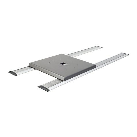
MOUNTING ON A DECK RAIL
First, make sure to have mounted the deck rail according
to its user manual. The bolts for mounting the chair to the
deck rail is already in place in the carrier wagon.
If you have an electrical deck rail and the cabling of the
switch is done by quick-connections already implemented
in the chairs column.
CARE AND MAINTENANCE OF LEATHER
As a natural product, leather is very durable and hardwearing, but all leather products require cleaning
and protection. By following these instructions, you will ensure a long and lasting leather quality. Never
place leather furniture closer than 20-30 cm to a radiator or in direct sunlight.
CARE AND MAINTENANCE OF FABRIC
Regular light vacuuming. Occasional cleaning should be done with a reputable brand of upholstery
shampoo following the manufacturer’s instructions
LEATHER CLEANING
Cleaning removes everyday dirt and stains from
your leather. Without proper cleaning the leather
will over a period of time leave grease spots or dis-
coloration’s. To avoid this, clean with So Cleaner
on a regular basis. We advise once a month.
LEATHER PROTECTION
Protect your leather to guarantee that the origi-
nal quality of the leather will be maintained. Use
Leather Protection Cream, we advise 2-4 times a
year. This will protect against spots and preserve
the leathers soness.
MAINTENANCE OF MOVING PARTS
Glide parts of the chair can be lubricated with a silicone-based lubricant. If the chair is on a deck rail, it is
important that the deck rails railway is NOT lubricated.
XL COLUMN
FLATOVAL COLUMN
XL column boom plate, may vary on chair setup and model.
CHANGING CUSHIONS
SEAT CUSHION  A1471
To change the seat cushion see accessing the interior.
When ordering new seat cushions, specify which chair model the cushion is for.
(example: A1471-1800 or A1471-4000)
BACKREST CUSHION  A2088
(1) Pull out the top of the backrest cushion from the molded backrest shield.
(2) Continue the pull until all the plugs are out, guide the backrest cushion down and out of the hooks.
1
2
ACCESSING THE INTERIOR
INTERIOR
(1) To gain access to the interior of the seat, use the seat depth adjustment to set the seat cushion in
max. Remove the pin and bolt, and slide the seat cushion away from the chair.
(2) To gain access to the interior of the armrest, all countersunk screws marked needs to be undone.
(3) To gain access to the interior of the column, four screws needs to be undone.
(The column may come with dierent looks and features)
1 3
2
Cushions - Seat
To remove the seat cushion, adjust the seat in a
forward position. This will make you able to see the
bracket for the gas spring.
Remove and secure the pin, then remove and
secure the bolt holding the gas spring in place. Pull
out the cushion from the gliders.
To install the seat cushion, slide the cushion on the
gliders. Position the cushion so that the bolt can
enter through the bracket and gas spring again.
Cushions - Standard Armrest
To remove the standard armrest cushion, begin by
unscrew 3 x
Screw Ø4,5 x19 A4 DIN 7983,
then pull the cushion straight out from the mold.
To install a new standard armrest cushion. Center
plugs to the corresponding holes in the mold, and
push them in. Then take the 3 x
Screw Ø4,5 x19 A4
DIN 7983,
and secure the cushion.
Number of adjustment buons may vary on chair setup and model
INSTALL OR ADJUST GAS SPRINGS
NORSAP 1800
1
43
3
1
2
NS 1800 Standard
Backrest - GAS-088
w/ GASDEL-024
Back crib - GAS-091
Front crib - GAS-091
w/ GASDEL-023
Seatpan - GAS-092
w/ GASDEL-024
Seat -GAS-092
w/ GASDEL-023
4
To remove a Gas springs for the seat movement,
follow the instruction on how to remove Seat cushion
and Standard armrest cushion.
The Gas spring(s) are located under the seat cushion.
Secure all screws and parts on a clean and so surface.
Aer removing the Seat and Standard armrest
cushion, the operation may require to remove the
Standard armrest, Circular armrest lidd and cover if
replacing the Hydraulic release buons.
NOTE: Do not use pliers without any so protection
when holding the piston for the release buon.
Any marks on the piston may cause loss of preassure
and the dedicated Gas spring will not be lock or release.
Locate which Gas spring that needs to be replaced.
Follow the hydraulic tube to or from the armrest, and
remove the bracket located in the armrest.
Remove the Gas spring with the release cap.
Note which order washers and nuts are mounted in,
before unscrewing the the Gas spring and release cap.
2
2
Description Gas springs
GAS-088 - 085-273 / 500N
GAS-091 - 085-273 / 300N
GAS-092 - 090-296 / 50N
Description Release caps
GASDEL-023 - 1000 mm
GASDEL-024 - 1200 mm
Mount the Gas spring rst, then guide the hydraulic
cable through the seat base and up into the upper
part of the armrest. Aach the Circular armrest lidd
and cover.
Mount the Hydraulic buon to the bracket and at-
tach the Standard armrest cushion back on.
Mount on the armrest while checking for unwanted
strain or pressure on the hydraulic cables.
Check the seat functions while operating the but-
tons from the chair.
If all functions is working, mount on the Seat cush-
ion.
To install the new Gas spring.
When monting on the Gas spring to the release
cap, screw the Gas spring on CC the release cap
until you feel resistance.
The resistance will vary on the preload force the
Gas spring has.
Use the at surfaces on the mounting end of the
Gas spring as reference to the release cap, screw
the Gas spring CCW 30 minues / 180 degrees.
Without rotating the release cap any further,
tighten the nut against the realease cap by hand.
Locking the position of the release cap on the Gas
spring.
Thighten the nut with suitable tools.
The release cap and piston can now be rotated
together for aligning the mounting holes for the
installation.
NOTE : Do not use force when manipulating the
hydraulic cable. If the cable loses it’s tubular shape
it may not engage or disengage the Gas spring cor-
rectly.
At any point, do not try to loosen, adjust or change
angel on the ends on the plastic tubing.
SAFETY FIRST:
When changing Gas spring or
Actuators, be careful between
moving parts and support the
movement before removing the
Gas spring or Actuators.
OVERVIEW OF ACTUATORS AND GAS SPRINGS
NORSAP 4000
1
3
4
2
2
To gain access to the actuators and gas springs,
begin with seat depth adjustment set to maximum
length.
Or set the seat sliding / underarm length to mini-
mum length. This adjustment will make the next
step easier.
Pull out the hairpin coer pin, and remove the
clevis pin holding the actuator in place.
Slide the seat cushion o the chair, and secure the
parts on a clean and so surface.
Please contact our head oce for troubleshooting
or removal of actuators and gas springs.
3
1
2
NS 4000 Standard
Backrest
- AKT-036
150 / 1500N
- GAS-093 155-302 / 700N
Back crib
- AKT-033
85 / 1200N
- GAS-086 090-292 / 700N
Front crib
- AKT-033
85 / 1200N
- GAS-086 090-292 / 700N
Seatpan
- AKT-035
100 / 1500N
Seat
- AKT-034
120 / 1800N
Footrest
- AKT-037
190 / 900N
4
2
SAFETY FIRST:
When changing Actuators, be sure
that the chair is not connected to a
power source and be careful be-
tween moving parts and support
the movement before removing the
Gas spring or Actuators.
ADJUSTMENT MODULES
NORSAP 1800 S / 1800 M / 4000
NorSap 4000 - RHS Electrical module
Norsap sparepart description / art.nr.:
Plastic buon for 1800 S GASDEL-029
Round stickers (6pcs) for 1800 S P18719
Sign for 1800 M (
RHS)
w/hight symbol P17244
Sign for 1800 M
(RHS)
wo/hight symbol P19012
Electrical membrane keyboard
(RHS)
for 4000 ELDEL-135
Lumbar membrane keyboard
(LHS)
for 4000 ELDEL-161
Rotation membrane keyboard for 4000 ELDEL-162
Deck rail membrane keyboard for 4000 ELDEL-163
Electrical and Gas spring adjustment modules
Replacing an electrical membrane keyboard or a
hydraulic Gas spring release circuit.
Follow the Changing the cushions and Install or ad-
just Gas springs to get access on the NS 1800 S.
Follow the instruction Accessing the interior,
Changing the cushions and
Install or adjust Gas springs to get access on
the NS 1800 M or NS 4000.
Hydraulic Gas spring release circuit is
not included in the modules.
NOTE: Stickers, signs and electrical membrane
keyboards is not reusable.
Norsap descripton / art.nr.:
Norsap 1800 S Gas spring module A1883-2
Norsap 1800 S Gas spring module A1883-3
Norsap 1800 M Gas spring module A2873
Norsap 4000 Electrical module A1875
Norsap 4000 Blind plate A2869
Norsap 4000 Memory module
(option)
A2832
NorSap 1800 M - RHS Gas spring module
NorSap 1800 S - LHS Gas spring module
Remember to check and set the rotation limit on
the new rotation unit before installing the chair top.
REMOVING THE COLUMN
NORSAP 1800
Start the process with adjusting the chair to the
lowest position, and pulling the chair top and
inner prole up. Secure the chair top and inner
prole by tighten the 2 x M8 set screws.
In some situations, the chair will have preinstalled
components and bigger armrests.
In these cases the 2 x M8 set screws will not
be able to hold the weight alone,
and the chair needs aditional support beams.
Use planks or other suitable objects from the
oor and up under the rotation unit, before
removing the 8 x M8x30 Buon head socket cap
screw.
Li the chair top with the gas spring up and away
from the column.
Move the support beams from the old column
to the new column, and position the beams from
the oor and up under the rotation unit.
Position the chair top onto the new column and
secure the chair top to the rotation unit, with the
8 x M8x30 Buon head socket cap screw.
Seperating the column from the rotation unit
Remove the 8 x M6x30 and mount it back on
the new column.
The rotation unit is standard on all standard
chairs with hydraulic adjustments, and can be
replaced with a suitable adapter plate.
Chairs without rotation may have dierent x-
ture for the gas spring located in the column.
CONTROL UNIT DIAGRAM
RESETTING THE ACTUATOR
RESETTING THE CONTROL UNIT
Press and hold hold together for 10 seconds.
Aerwards, control unit will beep.
The chair must be initialized aer a reset.
INITIALIZATION THE CONTROL UNIT
The initialization will run all actuators, to
dene their position. Press and hold the three
buons throughout the initialization, until all
movement has stopped. There will be a total
of six movements, that ends with the backrest
being set in a upright position.
CONNECTION DIAGRAM
There are one power input, two signal input and
seven signal output/channels.
Power Power in
IN1 Chair adjustment membrane panel
IN2 Chair memory membrane panel
WARNING:
If power cable (24V) from Control power unit is inserted in other than Power, the Control unit will
shorting.
Output/channel:
CH1 Seat height front
CH2 Seat height rear
CH3 Footrest
CH4 Backrest
CH5 Seat slide
CH6 Seat depth
IN
POWER OUT
1 2 1 2 3 4 5 6
NORSAP 4000
CONTROL UNIT MODULES
The control unit consist of two modules.
- Duty cycle: 10% ˜ max. 2 min. continuous use
followed by 18 min. not in use.
- Ambient temperature +5˚ to + 40˚C
- Approvals: IEC60601-1:2005 3rd ed., ANSI / AAMI
ES60601-1:2005, 3rd edition, CAN/CSA-22.2
No 60601-1:2008 approved
CONTROL POWER MODULE
- 230V or 110V for U.S
- IPX6 (cannot be used for Washable systems)
- 200W transformer (24V output)
- Class1 (with earth)
SYSTEM CONTROL UNIT MODULE
- 6 channels
- IPX6 (cannot be used for Washable systems)
- With EEPROM and 128kb FLASH
- 24V input
CONTROL UNIT ELDEL115

This manual suits for next models

7

Other NorSap Indoor Furnishing manuals

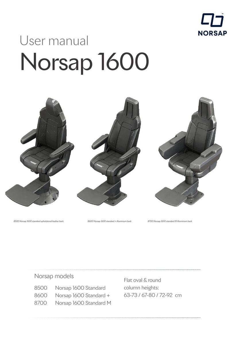
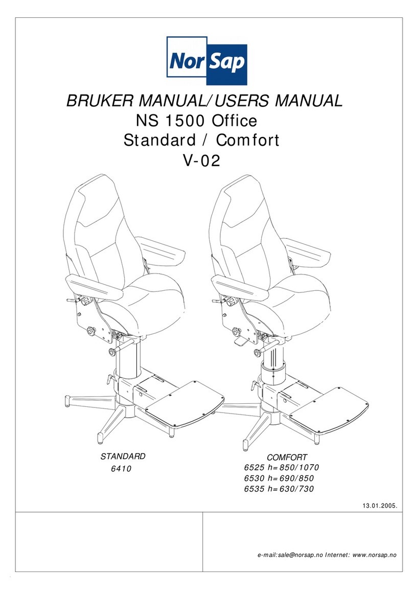
NorSap NS 1500 Office Standard User manual

NorSap

NorSap NS 1500 Office Standard User manual

NorSap 1100 User manual

NorSap

NorSap 1100 User manual

NorSap NS 1500 Office Standard User manual

NorSap

NorSap NS 1500 Office Standard User manual

NorSap 6650 Series User manual

NorSap

NorSap 6650 Series User manual

NorSap 1000 User manual

NorSap

NorSap 1000 User manual

NorSap 800 Sailor User manual

NorSap

NorSap 800 Sailor User manual

NorSap 1600 Standard User manual

NorSap

NorSap 1600 Standard User manual

Popular Indoor Furnishing manuals by other brands

Boahaus 1603 Assembly instructions

Boahaus

Boahaus 1603 Assembly instructions

Universal Furniture 192380 instruction sheet

Universal Furniture

Universal Furniture 192380 instruction sheet

Costway JZ10099CF user manual

Costway

Costway JZ10099CF user manual

Home affaire Ashton DB SH47 Assembly instructions

Home affaire

Home affaire Ashton DB SH47 Assembly instructions

Trendstyle base cabinet quick start guide

Trendstyle

Trendstyle base cabinet quick start guide

Ameriwood HOME 1199207PCOM Instruction booklet

Ameriwood HOME

Ameriwood HOME 1199207PCOM Instruction booklet

Comfort Products OneSpace 50-148501 Assembly instructions

Comfort Products

Comfort Products OneSpace 50-148501 Assembly instructions

Breezesta CI-1802 Assembly

Breezesta

Breezesta CI-1802 Assembly

BDI SEQUEL OFFICE instruction manual

BDI

BDI SEQUEL OFFICE instruction manual

HULALA HOME SBLS0867 manual

HULALA HOME

HULALA HOME SBLS0867 manual

Orange-Casual OC-WK-022 manual

Orange-Casual

Orange-Casual OC-WK-022 manual

Wilkhahn AT Series manual

Wilkhahn

Wilkhahn AT Series manual

Bretford LAP30ULV-CT user guide

Bretford

Bretford LAP30ULV-CT user guide

Next HOVE 137521 Assembly instructions

Next

Next HOVE 137521 Assembly instructions

JWA GARRISON 75134 Assembly instruction

JWA

JWA GARRISON 75134 Assembly instruction

VITRA Level 34 Instructions for use

VITRA

VITRA Level 34 Instructions for use

Amart Furniture KOBI 65770 Assembly instruction

Amart Furniture

Amart Furniture KOBI 65770 Assembly instruction

Enwork PROXI installation guide

Enwork

Enwork PROXI installation guide

manuals.online logo
manuals.online logoBrands
  • About & Mission
  • Contact us
  • Privacy Policy
  • Terms and Conditions

Copyright 2025 Manuals.Online. All Rights Reserved.