NorSap 6650 Series User manual

Users Manual
October 11, 2012 1:10 PM
NorSap Basic Deck Rail
Art. No.: 6650-XXXX, 6651-XXXX for the NorSap 1500 and NorSap 2000
Art. No.: 6652-XXXX, 6653-XXXX for the NorSap 1000
Art. No.: 6676-XXXX, 6677-XXXX for the NorSap 800

Introduction
Congratulations with your purchase of a NorSap chair and thank you for your condence in our company
products. NorSap is among the leading producers of helmsmen and operator seats for the maritime mar-
ket.
This manual will assist you in making the best use of the functional capabilities of the NorSap chair and
will ensure you will quickly become familiar with its use. If you have any questions regarding the safe and
eective operation of you NorSap chair or accessories after reading this manual, immediately contact our
head oce marketing department for further assistance.
NorSap AS
Mjåvannsveien 35
NO-4626 Kristiansand
NORWAY
Telephone
+47 38 18 52 00
Telefax
+47 38 18 20 86
E-mail
Web
norsap.com
Contents
Introduction 2
Mounting the top mounted deck rails 3
Detailed view 4
Installation of Deck Rails IMPORTANT NOTE 5
Installation of chair on a basic deck rail 6
Installation of chair on a basic deck rail part II 7
Installation of Basic Deck Rail release handle on chair 8
Wagon details 9
Flange modication necessary for the 800 Chair 10
Release handle details 11
Maintenance of moving parts 11
Safety 11
Shipping and storage specications 11
2

Mounting the top mounted deck rails
Due to material dierences of the wagon, the deck rail should be mounted in the following order:
1. Mount the rail with the locking tracks rst at desired place. This is your LEFT rail facing forward.
2. When the rail is mounted, place the plain rail parallel besides it, and slide the wagon on both rails.
3. Place the wagon to the one end of the mounted rail, and the mounting template on the other end,
and make sure the loose rail is parallel with the end of the mounted rail.
4. Make sure the distance is 367mm +/- 0,5mm between the mounting holes - and that the wagon is not
too tight nor too loose so that it travels rmly. Mount one screw at the current end of the rail.
5. Move the wagon to the other side, check for rm function and mount the second screw.
Test the rails function before mounting the rest of the screws.
This procedure ensures that the deck rail will function optimally and without any loose play.
When function of the deck rail is adequate, mount the stopping block
and end plugs on the rails, shown on the next page.
1
5
Front
2
33
4
90°
367 +/- 0,5mm
3
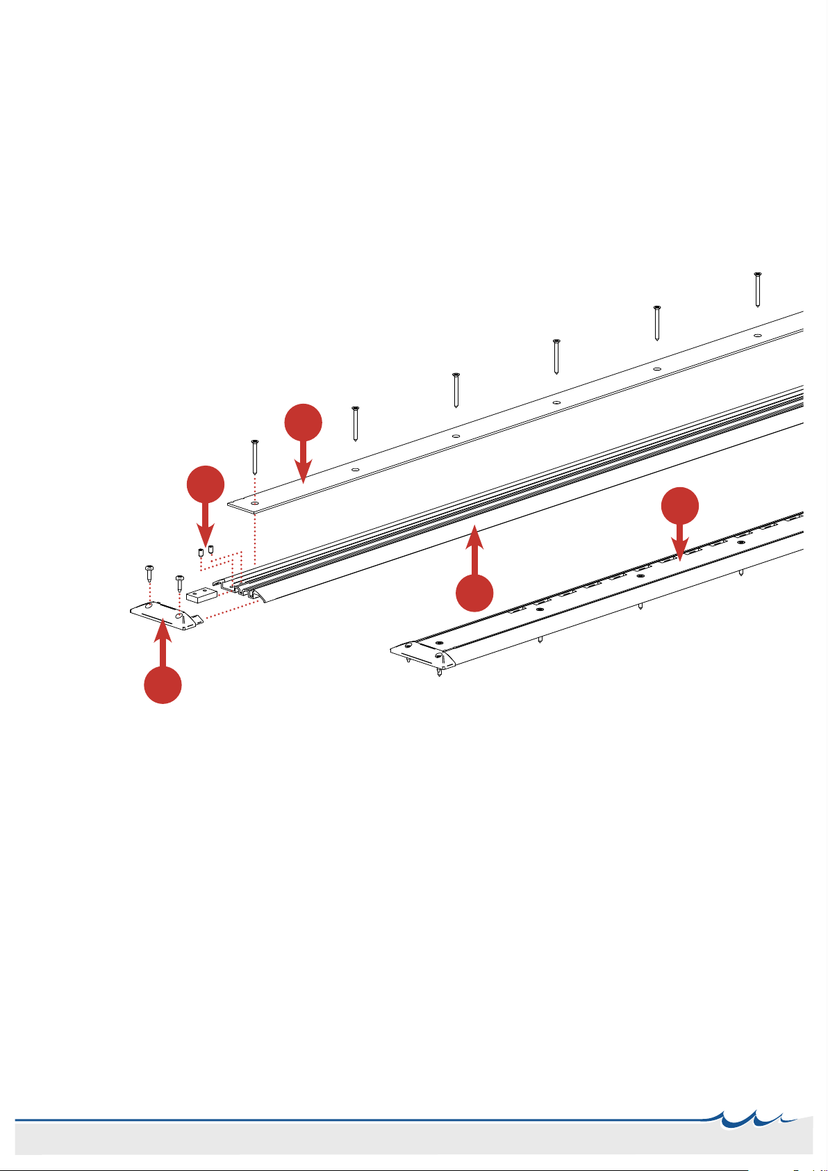
Detailed view
1. End plug for Top Mounted Basic Deck Rail MP248
2 x bolts for mounting 4.8x19 B430 4.8x19
2. Stop block for wagon SAP-3948
2 x bolts for mounting 6x10 B424 M6x10
3. Top rail cover without locking holes SAP-3949-XXXX (XXXX = length of rail)
To be mounted on the RIGHT side facing front
X number of bolts (depending on length) B434 4.8x50
4. Top rail cover with locking holes SAP-3950-XXXX
To be mounted on the LEFT side facing front
X number of bolts (depending on length) B434 4.8x50
5. 2 x Bottom rail prole, top mounted SAP-7135-XXXX
2 x Bottom rail prole, ush mounted SAP-3988-XXXX
1
5
2
4
3
Article numbers
Deck rails
Complete
6650-XXXX Basic Deck Rail for 1500 and 2000 Top Mounted
6651-XXXX Basic Deck Rail for 1500 and 2000 Flush Mounted
6652-XXXX Basic Deck Rail for 1000 Top Mounted
6653-XXXX Basic Deck Rail for 1000 Flush Mounted
6676-XXXX Basic Deck Rail for 800 Top Mounted
6677-XXXX Basic Deck Rail for 800 Flush Mounted
Spare parts
DEL-1190-XXXX Rail prole with locking holes Top mounted (single)
DEL-1189-XXXX Rail prole Top mounted (single)
DEL-1207-XXXX Rail prole with locking holes Flush mounted (single)
DEL-1208-XXXX Rail prole Flush mounted (single)
Wagons
Complete
DEL-1193 For the 1500 and 2000
DEL-1192 For the 1000
DEL-1206 For the 800
Spare parts
KLA-011 Spare Wheel
WIRE-022 Wire
DEL-1231 Release handle
4

Wagons
Complete
DEL-1193 For the 1500 and 2000
DEL-1192 For the 1000
DEL-1206 For the 800
Spare parts
KLA-011 Spare Wheel
WIRE-022 Wire
DEL-1231 Release handle
Installation of Deck Rails IMPORTANT NOTE
• A strong and level foundation is required to install the Deck Rail securely
• The assembly area and sliding tracks must be
free from scraps of metal or other items during installation
• Do not apply grease in the wheel tracks
• We do not stand liable if alterations are made by cutting or disassembling the Deck Rails;
any such work will be done at your own risk
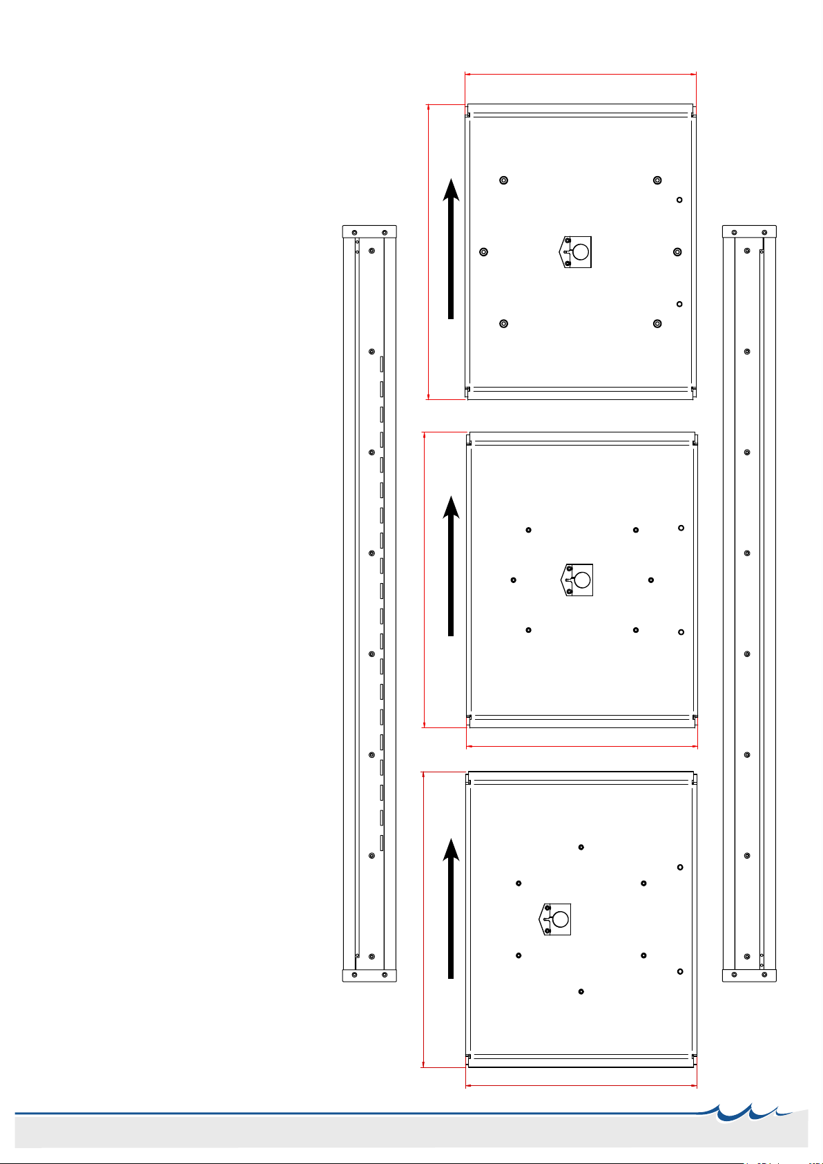
Mounting holes
The mounting holes must be parallel with a distance of 367+/-0.5 mm, this is standard for all lengths. Due
to material dierences the mounting procedure explained on page 2 is the recommended way to
mount the basic deck rail. This procedure should prevent the deck rails wagon to be mounted too
loosely.
107 282 107
496
367
37.8
367
444
446
107 282 107
496
367
37.8
367
444
446
50 200 200 200 200 200 200 200 50
200 200 200 200 200 200 200 250 50
250
50
200 200 200 200 200 200 200 200 200 100 50
200200100
50
200 200 200 200 200 200 200
200
200200
15050 200 200 200 150 50
37.8
367
444
306
446
567.2
70
70
306
1300
1500
1600
2200
3400
4600
5200
The following diagrams shows the spacing between the mounting holes from a 1500mm deck rail to a
3000mm deck rail. The two deck rail rails has a parallel distance of 282 mm, and the mounting holes are
367 mm. The mounting hole patterns length distance may vary.
50 | 200 | 200 | 200 ... ... 200 | 200 | 200 | 50
50 | 250 | 200 | 200 ... ... 200 | 200 | 250 | 50
50 | 100 | 200 | 200 ... ... 200 | 200 | 100 | 50
50 | 150 | 200 | 200 ... ... 200 | 200 | 150 | 50
1500mm2000mm2500mm3000mm
Top Mounted Flush Mounted
5
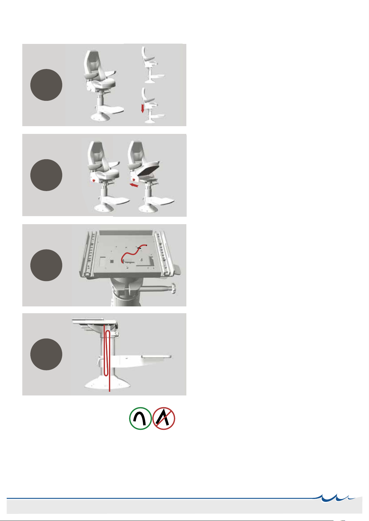
Installation of chair on a basic deck rail
S
T
E
P
0
1
S
T
E
P
0
3
Place the wire thru the designated hole in the seat
frame and down the column, nd a suitable path
for the wire from the release handle to the column.
(The chair top is hidden due to visualization) Use a
strip to fasten the wire.
Remember to leave some play for the wire
S
T
E
P
0
2
Remove the hand wheels on the side completely
and push the seat frame backwards until you gain
access to the center of the column.
Do not push the seat top all the way o.
Place the chair in the lower position and mount the
release handle according to chair model if not all
ready mounted (see page 8)
N
O
T
O
K
O
K
S
T
E
P
0
4
For NorSap 800 chairs, the wire will not t inside the
column and needs to be placed on the outside. The
wire should go thru the plastic ring on the side of
the footrest. See last page for ange modications
regarding the 800 series of NorSap chairs.
The wire needs soft corners, if its bent too
much the wire will be destroyed.
The wire is placed as shown on the image, down,up
and down within the column - to ensure that the
wire follows the movement of the columns rise and
lower.
6

IMPORTANT
Make sure the release cable goes straight from the release
handle on the wagon and up thru the column. Not under the
locking bolt of the column or any unnecessary twists.
Installation of chair on a basic deck rail part II
N
O
T
O
K
O
K
Place the chair on the wagon of the basic deck rail
- use a piece of cardboard for protective measures
when tilting the chair to gain access to the wire.
Place the wire end as shown on the illustration.
Place the ange over the designated hole pattern
and mount the ange onto the deck rails wagon
with the included bolts.
S
T
E
P
0
6
7
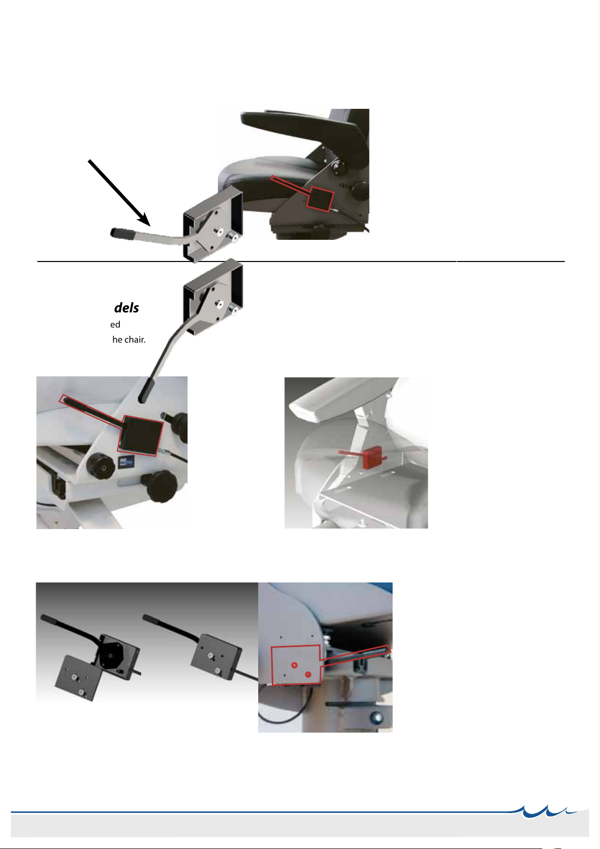
Installation of Basic Deck Rail release handle on chair
Back side
With adaptor plate (only applies to the NorSap 1500)
All other models
The handle is placed
bending towards the chair.
The handle is ipped to bend
away from the chair.
Make sure the release handle is “reversed”
/ pointing away from the seat.
Placement of the release handle on a
NorSap 800 chair. Use two M5 screws to
mount the handle.
NB, see illustration to the left.
Placement of the release handle on
a NorSap 1500 and 1700 chair.
Mount the adapter plate as shown
on the images above.
Countersink the two holes marked
with red circles (M5) if not present.
Use two M5 screws to mount the
handle. Mounts on the inside of
the plate. Use the adapter plate for
measurements.
Placement of the
release handle on
a NorSap 1000
chair. Use two M5
screws to mount
the handle.
Placement of the release
handle on a NorSap 2000
chair. Use two M5 screws to
mount the handle.
Flip up the seat rest to gain
access to the area.
NorSap 1000
NorSap 1500/1700
NorSap 2000
NorSap 800
8
Wagon details
- For the 1500 - 2000 Chairs
Complete 1500/2000 wagon DEL-1193
* Spare Wheel KLA-011
* Wire WIRE-022
* Release handle DEL-1231
- For the 1000 Chair
Complete 1000 wagon DEL-1192
* Spare Wheel KLA-011
* Wire WIRE-022
* Release handle DEL-1231
Navn:
FØRSTE TEGNING 10.05.2010
01
01 Vogn Basic 800
Name:
Weight:
Rev.
Author:Date:
REV: REVISION ISSUED FOR: EC no.
Filepath:
Toleranser for ikke toleransesatte mål: NS-ISO 2768-1 "MIDDELS" \\DC01\Tegninger\Standardprodukter SAP\Sammensatt 1001-\DEL-1206.asm
A4
Approved:
SOLID EDGE ST
Model Filename:
DEL-1206
Thickness:
Material:
Scale:
6,715 kg
1:5
_____
___
__
_____
___
__
_____
___
__
arild
_
567.2
444
36.2
2 stk. skruer til utløserhendel må leveres løst med
B434-4,2x19
- For the 800 Chair
Complete 800 wagon DEL-1206
* Spare Wheel KLA-011
* Wire WIRE-022
* Release handle DEL-1231
FRONT FRONT FRONT
Rail with locking track
Plain rail track
9
Ø8mm
70mm
Ø8mm
70mm
Ø8mm
70mm
Ø8mm
70mm
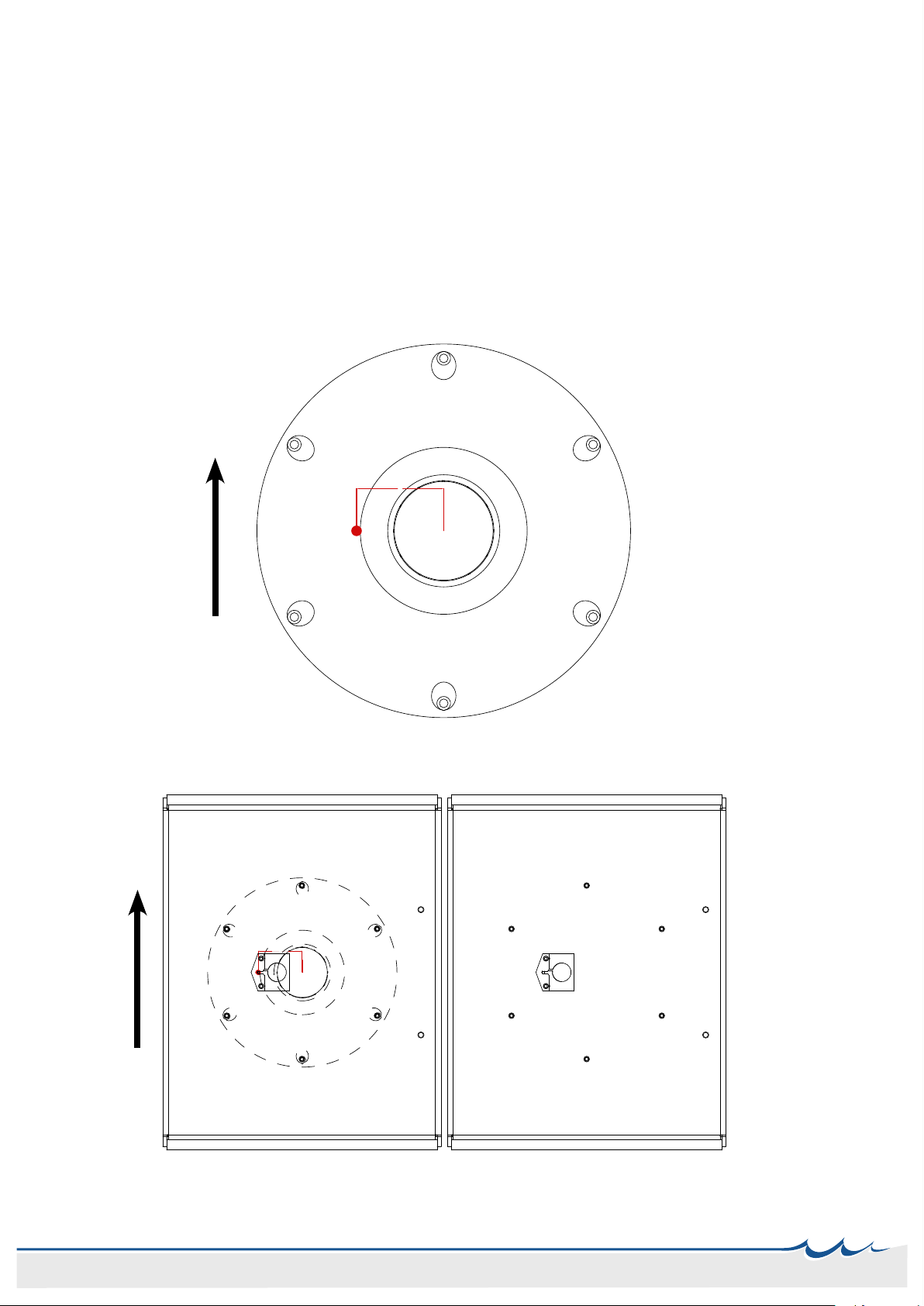
Flange modication necessary for the 800 Chair
The NorSap 800 chairs columns is too small to have the release wire for the deck rail concealed within the col-
umn. To be able to mount the NorSap 800 chair on a Basic Deck Rail, the ange needs to be modied.
70mm from the center of the ange towards the side where the wagons release cable goes,
drill a Ø8mm hole for the release wire insertion.
FRONT
FRONT
10

Maintenance of moving parts
The glide parts of the chair can be lubricated with a silicone based lubricant.
If the chair is on a deck rail, its important that the deck rails railway is NOT lubricated.
Safety
All moving parts has a potential squeezing hazard. Be sure to keep hands and ngers out of moving
parts areas when operating the chair.
Shipping and storage specications
The chair should be shipped and stored in an upright condition.
No other materials should be shipped or stored on top of a the chair or deck rail.
The chair should be shipped and stored at temperatures between -20°C and +40°C.
The chair should not be operated until its been acclimatized between 0°C and +30°C.
The chair should be kept in a clean, dry environment.
Upon receipt, we recommend that the shipping packaging be immediately examined for damage. Any
damage should be noted on the delivery receipt and a request for inspection by the transportation com-
pany should be made. The shipping packaging should be opened immediately and the chair or the deck
rail examined for concealed shipping damage.
If the chair appears to be damaged, a concealed bad order report should be immediately
led with the transportation company.
1
3
4
5
2
6
Pos. Ant. Vare Navn Vare Nr. Rev.
1 1 Boks for utløserspak basicsystem 02
2 1 Utløserspak for basic system. 02
3 2 Press avstandsstykke M5 tett B366-M5X14
4 3 SKIVE MYK PVC M6x16 KLAR B783-M6
5 2 UNBRACO SENK M5X16 B420-M5X16
6 1 Gummikappe for spak 01
1 Casing SAP-8037
2 Release handle SAP-8038
3 Spacer B366-M5x14
4 Washer B783-M6
5 Countesunk umb. B420-M5X16
6 Rubber tting GASDEL-019
Release handle details
11

NorSap as
Mjåvannsveien 35
4628 Kristiansand
Norway
Tel +47 38 18 52 00
Fax +47 38 18 20 86
sale@norsap.no
norsap.com
norsap.com
This manual suits for next models
5
Table of contents
Other NorSap Indoor Furnishing manuals


Popular Indoor Furnishing manuals by other brands

Agilent Technologies
Agilent Technologies InfinityLab Flex Bench Assembly and use instructions

Home Styles
Home Styles 20 05050 0941 quick start guide

GAMA
GAMA HUDS822 Assembling Instruction

DAVIDSEN
DAVIDSEN LANGO 9161776 Assembly manual

mlmeble
mlmeble Laptop Assembling Instruction

Baumax
Baumax Dreamer RMRS62411 Assembling Instruction


