Reznor, PREEVA Neos, Installation Manual, EN 2021-05, D301315 Iss 1 Page No 5 of 52
G
including short length final connections then
we advise that installers consult with the gas
supplier or provider and satisfy themselves
what additional precautions may be necessary.
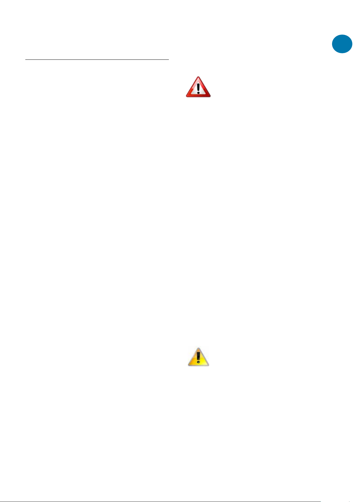
Improper installation, adjustment,
alteration, service, or maintenance
can cause property damage,
injury, or death. Read the
installation, operation, and
maintenance instructions
thoroughly before installing or
servicing this equipment.
Gas-fired appliances are not designed for
use in hazardous atmospheres containing
flammable vapours or combustible dust,
in atmospheres containing chlorinated or
halogenated hydrocarbons or in applications
with airborne silicone substances.
Any reference made to Laws, Standards,
Directives, Codes of Practice or other
recommendations governing the application
and installation of heating appliances and
which may be referred to in Brochures,
Specifications, Quotations, and Installation,
Operation and Maintenance manuals is done
so for information and guidance purposes only
and should only be considered valid at the
time of the publication.
The manufacturer cannot be held responsible
from any matters arising from the revision
to or introduction of new Laws, Standards,
Directives, Codes of Practice or other
recommendations.
External Units
Care must be taken when
installing air heaters in outdoor
locations to ensure that
unauthorised access to the
building cannot be gained via the
appliance or its ductwork system.
The unit can be installed using
full fresh air or a combination of
fresh air and recirculation air; the
unit must be provided with an
additional air intake complete with
a water separator.
Important notice to
installers
Before installation, carefully read these
instructions and follow the processes explained
by the manufacturer. These instructions are
only valid for appliances designed to operate in
Europe. If the country code and gas category
on the appliance data label does not match
the country of installation or the country codes
and gas categories as shown in this instruction
manual, it will be necessary to contact the
distributor or manufacturer to provide the
necessary information for the modification of
the appliance to the conditions of use for the
country of installation.
Installing, commissioning, testing,
programming and maintenance of these
products must only be carried out by suitably
qualified and trained technicians and in full
compliance with all applicable regulations and
current best practices.
Check if the appliance as described on the
packaging label is in accordance with the
correct type and model as specified on the
data plate and complies with your customer
order.
Check that the temperature ranges given
and those of the location match. The
appliance must be powered with a voltage
corresponding to the value shown on the
rating plate.
These units must be installed in accordance
with the rules in force and local regulations /
legislation as appropriate plus all local building
codes. Installers should satisfy themselves that
the gas pipework installation is carried out in
accordance with all current legislation, Codes
of Practice and recommendations.
Additionally it may be necessary to protect
the gas valves which form part of the heater
or burner assembly from potential pipe
contamination particularly, but not exclusively,
where copper gas pipework is used. In
instances where copper pipework is to be used
for all or part of a gas pipework installation,