Page 1
INSTALLATION INSTRUCTIONS
Roof Curb Kit for R7TQ 072/090/120 Series
Curb sides are constructed of 16-gauge coated steel and
wooden nailers. All hardware necessary to assemble the
curb is provided; installation hardware must be field supplied.
Vertical discharge roof curbs include dividers that allow for
inserting ductwork down from the top. Curbs are constructed
of 16-gauge coated steel and 2 × 4 wooden nailers.
TABLE 1. CURB IDENTIFICATION
1011391 8” 203.2 mm
1011388 14” 355.6 mm
1011389 18” 457.2 mm
1011390 24” 609.6 mm
• Assembly and installation of the curb are the
responsibility of the installer.
• Before installation, verify that the curb ordered is the
appropriate one for the unit. Refer to Tables 1, 2 and 3.
• Depending on the weight and the roof structure, tread
material may be required under the rails. Curb and
equipment must be level.
• If installing more than one system, it is recommended to
minimize structural span deflection to discourage sound
transmission.
• Mounting hardware and flashing must be field supplied.
• Check the roof curb for squareness. The curb must be
adjusted so that the diagonal measurements are equal
within a tolerance of ±1/8” (±3 mm).
• Level the roof curb. To ensure a good weatherproof seal
between the unit curb cap and the roof curb, the roof curb
must be leveled in both directions with no twist end to
end. Shim as required and secure curb to the roof deck
before installing flashing.
• Install field-supplied flashing. If ductwork is being installed
from the top, slide the ductwork down into the discharge
and return air openings. Ductwork should be sized slightly
smaller with a minimum 3/4” duct flange that will rest on
and be attached to all sides of the duct connection. See
the system installation manual for ductwork requirements.
• Apply 1/4” x 1-1/4” foam sealant tape to both the
top surface of the curb rails and the top surface of
the perimeter of the integral dividers, being sure to
make good butt joints at all corners. The sealant
tape must be applied to prevent water leakage into
the curb area due to blown rain and capillary action.
IMPORTANT:Verify that the unit will be placed in the correct
airflow orientation to mate properly with the discharge and
return air openings.
TABLE 2. CURB PART NUMBERS
HEIGHT ITEM # P/N DESCRIPTION QTY
8”
1 1006197 END 2
2 1006198 CONTROL SIDE 1
3 1006199 FILTER ACCESS SIDE 1
14”
1 1006186 END 2
2 1006187 CONTROL SIDE 1
3 1006188 FILTER ACCESS SIDE 1
18”
1 1006191 END 2
2 1006192 CONTROL SIDE 1
3 1006193 FILTER ACCESS SIDE 1
24”
1 1006194 END 2
2 1006195 CONTROL SIDE 1
3 1006196 FILTER ACCESS SIDE 1
P/N ITEM DESCRIPTION QUANTITY
See Curb
Part Number
Table
1 Curb End 2
2 Curb Filter Access side 1
3 Curb Control side 1
TABLE 3. BILL OF MATERIALS
1006182 4 Support 1
1006185 5 RA Support 1
1006184 6 SA Support 1
600255 7 Screws S.M. 10AB x 1/2” 4
16247 8 5/16”-18 x 3/4” Hex Cap
Screws
16
612001 9 Washers 32
1035 10 5/16”-18 Hex Nut 16
66302 11 Gasket 1/4” x 1 1/4” 50 FT
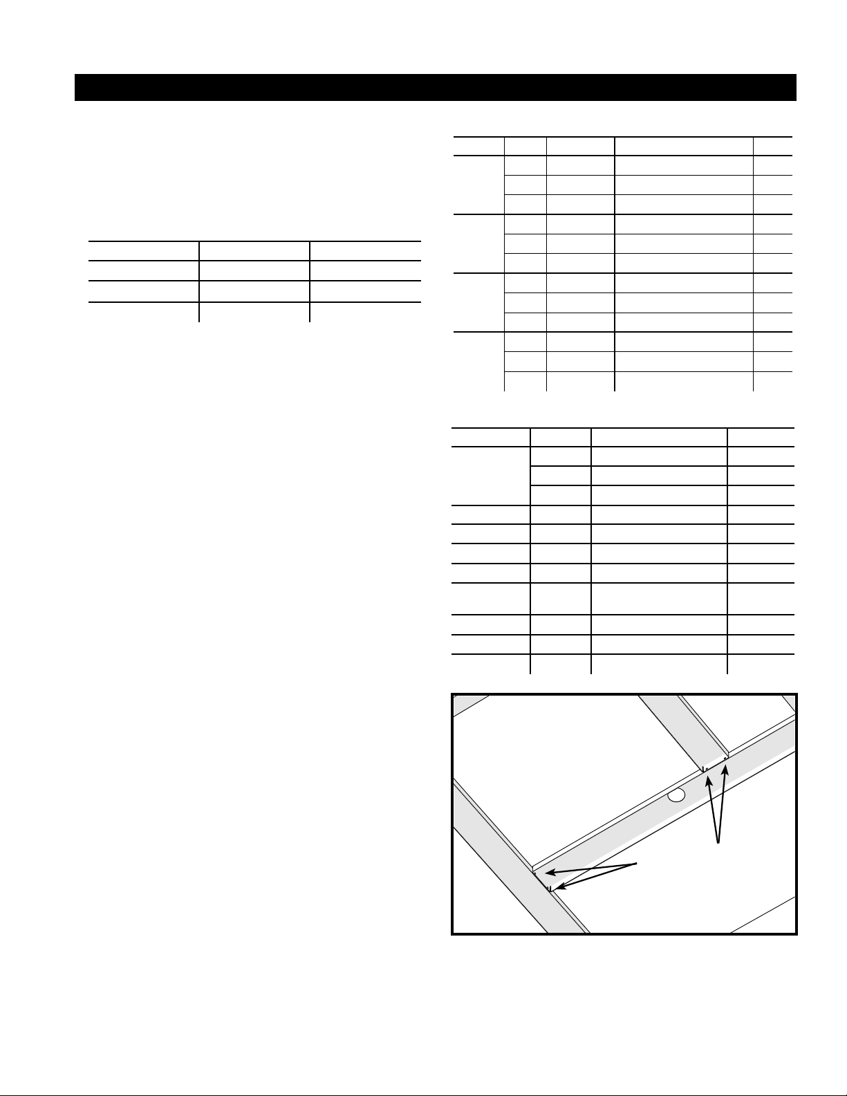
Figure 1. Support and Gasket Locations
5
6
4#7 Fastener
locations
Bottom side view
of supports
Refer to Table 3
for item numbers
Form R7TQ-072/090/120 (03-18) PN1012100A,


