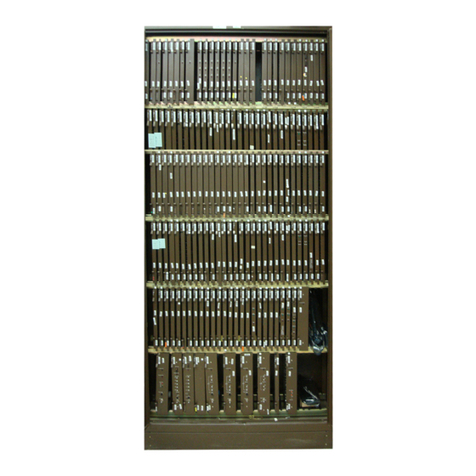
Nortel DMS-100 Series User manual

Critical Release Notice
Publication number: 297-8351-550
Publication release: Standard 04.02
The content of this customer NTP supports the
SN06 (DMS) and ISN06 (TDM) software releases.
Bookmarks used in this NTP highlight the changes between the baseline NTP and the current
release. The bookmarks provided are color-coded to identify release-specific content changes. NTP
volumes that do not contain bookmarks indicate that the baseline NTP remains unchanged and is
valid for the current release.
Bookmark Color Legend
Black: Applies to new or modified content for the baseline NTP that is valid through the
current release.
Red: Applies to new or modified content for NA017/ISN04 (TDM) that is valid through the
current release.
Blue: Applies to new or modified content for NA018 (SN05 DMS)/ISN05 (TDM) that is valid
through the current release.
Green: Applies to new or modified content for SN06 (DMS)/ISN06 (TDM) that is valid
through the current release.
Attention!
Adobe
Acrobat
Reader
5.0 is required to view bookmarks in color.

Publication History
March 2004
Standard release 04.02 for software release SN06 (DMS) and ISN06 (TDM).
Change of phone number from 1-800-684-2273 to 1-877-662-5669, Option 4 + 1.

XPM12 and up Standard 04.01 August 1999
297–8351–550
DMS-100 Family
Remote Line Concentrating Module
Maintenance Manual


DMS-100 Family RLCM Maintenance Manual XPM12 and up
DMS-100 Family
Remote Line Concentrating Module
Maintenance Manual
Copyright 1996, 1997, 1998, 1999 Nortel Networks,
All Rights Reserved
Printed in the United States of America
NORTEL NETWORKS CONFIDENTIAL: The information contained herein is the property of Nortel Networks and is
strictly confidential. Except as expressly authorized in writing by Nortel Networks, the holder shall keep all information
contained herein confidential, shall disclose the information only to its employees with a need to know, and shall protect the
information, in whole or in part, from disclosure and dissemination to third parties with the same degree of care it uses to
protect its own confidential information, but with no less than reasonable care. Except as expressly authorized in writing by
Nortel Networks, the holder is granted no rights to use the information contained herein.
Information is subject to change without notice. Nortel Networks reserves the right to make changes in design or components
as progress in engineering and manufacturing may warrant.
.
DMS
,
MAP, NORTEL, NORTEL NETWORKS, NORTHERN TELECOM, NT,
and
SUPERNODE
are trademarks of Nortel
Networks Corporation. HP and OpenView are trademarks and Hewlett-Packard is a registered trademark of the
Hewlett-Packard Company. Sun is a trademark or registered trademark of Sun Microsystems, Inc. in the United States and
other countries.
Publication number: 297–8351–550
Product release: XPM12 and up
Document release: Standard 04.01
Date: August 1999


DMS-100 Family RLCM Maintenance Manual XPM12 and up
iii
Contents
About this document ix
When to use this document ix
How to check the version and issue of this document ix
References in this document x
What precautionary messages mean x
How commands, parameters, and responses are represented xi
Input prompt (>) xi
Commands and fixed parameters xi
Variables xi
Responses xii
Maintenance overview 1-1
Functional overview 1-1
Hardware description 1-1
General configuration 1-2
Line concentrating module 1-2
LCA shelf configuration 1-4
LCM control complex cards 1-5
Line drawers 1-7
HIE description 1-15
Intracalling channel availability 1-19
ESA channel availability 1-25
1-Meg Modem Service 1-28
Remote maintenance module (RMM) 1-34
Frame supervisory panel (FSP) 1-39
Software description 1-40
Functional limits 1-42
Fault conditions 1-43
LCA shelf failure 1-43
Line drawer faults 1-43
Link failure 1-43
Load file mismatch 1-44
Automatic maintenance 1-44
RLCM audits 1-45
Checksums 1-46
LCM LTC speech path diagnostics enhancements 1-46
Overload resources 1-48
Takeover capability 1-56
LCM talk battery audit 1-57
ESA capability 1-64

iv Contents
297–8351–550 Standard 04.01 August 1999
RMM maintenance 1-64
Drawer testing 1-64
BIC relay test (BRT) 1-67
Subscriber lines automatic maintenance 1-75
LCM REXTEST 1-75
System REX controller: XPM maintenance 1-77
Increase to manual maintenance 1-84
Alarm conditions 1-84
Subscriber lines manual maintenance 1-86
Drawer maintenance 1-86
PRLCM overview 2-1
PRLCM configuration 2-1
International line concentrating module 2-3
Host interface equipment shelf 2-3
Remote maintenance module 2-9
Frame supervisory panel 2-9
Emergency stand alone description 2-11
ESA hardware model 2-12
ESA operation 2-13
ESA hardware 2-14
Intracalling during ESA mode 2-16
ESA call processing 2-16
Channel configuration 2-16
Exiting PRLCM ESA mode 2-17
ESA maintenance overview 3-1
Functional description 3-1
ESA hardware representation 3-1
ESA operation 3-3
ESA hardware 3-4
In-service firmware downloading 3-9
Software operation 3-12
Intracalling during ESA mode 3-12
ESA call processing 3-12
ESA translation data 3-18
Supported subscriber line types 3-18
Supported subscriber services 3-19
Channel configuration 3-20
Exiting RLCM ESA mode 3-21
Tones during ESA mode 3-23
Ringing during ESA mode 3-25
Treatments during ESA mode 3-25
ESA limits 3-25
Fault conditions 3-27
Unusable communication links 3-27
Looparound message audit failure 3-27
Automatic ESA maintenance 3-28
ESA line audits 3-28
Digitone receiver audit 3-28
Automatic static data downloading and system maintenance 3-29

Contents v
DMS-100 Family RLCM Maintenance Manual XPM12 and up
Routine exercise test 3-29
ESA ROM diagnostics 3-30
ESA RAM diagnostics 3-31
Escalation to manual maintenance 3-31
Loading ESA static translations data 3-31
ESA manual exit 3-32
LTC maintenance to prevent ESA mode 3-32
Signaling for RLCM 4-1
RLCM signaling links 4-1
Signaling protocol 4-2
Signaling functions 4-4
1-Meg Modem Service supported protocols 4-8
DBIC 4-8
xLC and loop 4-9
1-Meg Modem 4-9
RLCM hardware 5-1
RLCM hardware components 5-1
Hardware configuration 5-1
Line concentrating module 5-1
Host interface equipment 5-4
Frame supervisory panel 5-4
Additional RLCM components 5-4
HIE components 5-4
Remote maintenance module 5-5
Convertible RLCM 5-5
RLCM recovery procedures 6-1
RLCM recovery procedure 6-2
RLCM alarm clearing procedures 7-1
RLCM critical 7-2
RLCM RG critical 7-17
RLCM talk battery alarm critical 7-27
RLCM major 7-42
RLCM RG major 7-52
Ext FSP RLCE frame major 7-62
RMM major 7-86
RLCM minor 7-96
PM LCM RG minor 7-110
RMM minor 7-120
ESA critical, minor 7-126
RLCM card replacement procedures 8-1
NT0X10 in RMM 8-2
NT0X91 RLCE 8-6
NT2X06 RMM 8-20
NT2X09 RMM 8-28
NT2X10 RMM 8-36

vi Contents
297–8351–550 Standard 04.01 August 1999
NT2X11 RMM 8-40
NT2X48 RMM 8-44
NT2X57 RMM 8-49
NT2X59 RMM 8-53
NT2X70 HIE 8-59
NT2X90 RMM 8-75
NT3X09 RMM 8-81
NT6X17 RLCM 8-86
NT6X18 RLCM 8-90
NT6X19 RLCM 8-95
NT6X20 RLCM 8-99
NT6X21 RLCM 8-103
NT6X27 in HIE 8-108
NT6X36 RLCE 8-116
NT6X45 HIE 8-121
NT6X47 HIE 8-128
NT6X50 HIE 8-135
NT6X51 RLCM 8-143
NT6X52 RLCM 8-151
NT6X53 RLCM 8-158
NT6X54 RLCM 8-168
NT6X60 HIE 8-178
NT6X71 RLCM 8-186
NT6X73 HIE 8-190
NT6X74 RMM 8-195
NT6X75 HIE 8-203
NT6X99 RLCM 8-211
NTEX17 RLCM 8-215
NTEX54 RLCM 8-226
NTMX45 HIE 8-244
Replacing a card RLCM 8-255
Replacing a line card RLCM 8-261
RLCM trouble locating and clearing 9-1
Trouble isolation and correction 10-1
Description of troubleshooting procedures 10-1
Performance indicators 10-1
Locating and clearing faults 10-2
Fault isolation tests 10-3
Defective line drawer 10-3
Defective shelf circuit pack 10-3
Defective line card 10-3
Defective DS-1 link 10-4
Defective ringing generator (RG) frequency generator circuit 10-5
Load file mismatch 10-5
Diagnostic tests 10-5
Bit error rate performance tests 10-5
XPM bit error ratio test 10-6
Entering XBERT 10-8
Lines maintenance 10-8

Contents vii
DMS-100 Family RLCM Maintenance Manual XPM12 and up
Automatic line tests 10-8
Station tests 10-10
Manual line tests 10-11
Ring pretrip on LCM lines 10-11
Product-specific test tools 10-14
Line maintenance cutover (LMCUT) 10-14
Troubleshooting chart 11-1
Advanced troubleshooting procedures 12-1
Powering up the RLCM 12-1
Powering down the RLCM 12-2
Common procedures 12-3
Troubleshooting a failure to load 12-3
Troubleshooting RTS failure 12-6
Troubleshooting dial tone problems 12-6
Troubleshooting ringing generator problems 12-7
RLCM routine maintenance procedures 13-1
Inspecting spare fuse holders RLCM 13-2
Testing power converter voltages HIE 13-5
Returning a card for repair or replacement RLCE 13-8
Testing wriststrap grounding cords RLCM 13-12
Index 14-1


DMS-100 Family RLCM Maintenance Manual XPM12 and up
ix
About this document
When to use this document
This Remote Line Concentrating Module with Extended Distance Capability
(RLCM-EDC) maintenance reference manual provides: overview, signal-
ing, and hardware information for understanding the RLCM-EDC product
and operation; recovery procedure for returning to service an RLCM-EDC
from a completely out-of-service condition; alarm clearing procedures for
clearing an RLCM-EDC alarm condition at the MAP display terminal; card
replacement procedures for removing and replacing hardware modules in the
RLCM-EDC as part of maintenance, verification, or acceptance procedures;
trouble locating and clearing information for locating and clearing problems
beyond the scope of other maintenance procedures; routine maintenance
procedures for performing scheduled routine and preventive maintenance
tasks. The information in this maintenance manual is intended for operating
company personnel engaged in RLCM-EDC maintenance.
How to check the version and issue of this document
The version and issue of the document are indicated by numbers, for
example, 01.01.
The first two digits indicate the version. The version number increases each
time the document is updated to support a new software release. For
example, the first release of a document is 01.01. In the next software
release cycle, the first release of the same document is 02.01.
The second two digits indicate the issue. The issue number increases each
time the document is revised but rereleased in the same software release
cycle. For example, the second release of a document in the same software
release cycle is 01.02.
To determine which version of this document applies to the software in your
office and how documentation for your product is organized, check the
release information in Product Documentation Directory, 297-8991-001.
This document is written for all DMS-100 Family offices. More than one
version of this document may exist. To determine whether you have the
latest version of this document and how documentation for your product is

x About this document
297–8351–550 Standard 04.01 August 1999
organized, check the release information in Product Documentation
Directory, 297-8991-001.
References in this document
The following documents are referred to in this document:
•Operational Measurements Reference Manual
•Input/Output System Reference Manual, 297-1001-129
•Extended Peripheral Module Translations Reference Manual
•Provisioning Guide, PLN-8991-104
•1-Meg Modem Network Implementation Manual, 297-8063-200
What precautionary messages mean
The types of precautionary messages used in NT documents include
attention boxes and danger, warning, and caution messages.
An attention box identifies information that is necessary for the proper
performance of a procedure or task or the correct interpretation of
information or data. Danger, warning, and caution messages indicate
possible risks.
Examples of the precautionary messages follow.
ATTENTION Information needed to perform a task
ATTENTION
If the unused DS-3 ports are not deprovisioned before a DS-1/VT
Mapper is installed, the DS-1 traffic will not be carried through the
DS-1/VT Mapper, even though the DS-1/VT Mapper is properly
provisioned.
DANGER Possibility of personal injury
DANGER
Risk of electrocution
Do not open the front panel of the inverter unless fuses
F1, F2, and F3 have been removed. The inverter contains
high-voltage lines. Until the fuses are removed, the
high-voltage lines are active, and you risk being
electrocuted.

About this document xi
DMS-100 Family RLCM Maintenance Manual XPM12 and up
WARNING Possibility of equipment damage
WARNING
Damage to the backplane connector pins
Align the card before seating it, to avoid bending the
backplane connector pins. Use light thumb pressure to
align the card with the connectors. Next, use the levers on
the card to seat the card into the connectors.
CAUTION Possibility of service interruption or degradation
CAUTION
Possible loss of service
Before continuing, confirm that you are removing the card
from the inactive unit of the peripheral module.
Subscriber service will be lost if you remove a card from
the active unit.
How commands, parameters, and responses are represented
Commands, parameters, and responses in this document conform to the
following conventions.
Input prompt (>)
An input prompt (>) indicates that the information that follows is a
command:
>BSY
Commands and fixed parameters
Commands and fixed parameters that are entered at a MAP terminal are
shown in uppercase letters:
>BSY CTRL
Variables
Variables are shown in lowercase letters:
>BSY CTRL ctrl_no
The letters or numbers that the variable represents must be entered. Each
variable is explained in a list that follows the command string.

xii About this document
297–8351–550 Standard 04.01 August 1999
Responses
Responses correspond to the MAP display and are shown in a different type:
FP 3 Busy CTRL 0: Command request has been submitted.
FP 3 Busy CTRL 0: Command passed.
The following excerpt from a procedure shows the command syntax used in
this document:
Manually busy the CTRL on the inactive plane by typing
>BSY CTRL ctrl_no
and pressing the Enter key.
where
ctrl_no is the number of the CTRL (0 or 1)
Example of a MAP response
:
FP 3 Busy CTRL 0: Command request has been submitted.
FP 3 Busy CTRL 0: Command passed.
1

DMS-100 Family RLCM Maintenance Manual XPM12 and up
1-1
Maintenance overview
The Remote Line Concentrating Module (RLCM) is a remote peripheral that
provides extended geographic coverage for the Digital Multiplex
System-100 (DMS-100) switch. The RLCM operates at a maximum of
160.9 km (100 mi) from the host office.
The RLCM contains hardware and software maintenance components that
perform routine audits and identify failures in the following:
•RLCM
•DS-1 links that connect the RLCM to the host controller
•subscriber lines
Functional overview
The RLCM provides an interface for two to six DS-1 links from
•a line group controller (LGC)
•a line trunk controller (LTC)
•a remote cluster controller (RCC)
•a remote cluster controller2 (RCC2)
•a maximum of 640 subscriber lines that connect locally
Note: When interfacing an RCC or RCC2 in the remote-off-remote
configuration, use software package NTX381AA.
This chapter contains a hardware and software summary of the RLCM
configuration.
Hardware description
This section can help the maintenance engineer understand how the different
hardware components of the RLCM interact for maintenance
troubleshooting. The following paragraphs describe the hardware required
for the Remote Line Concentrating Module, NTX146AA, feature package.

1-2 Maintenance overview
297–8351–550 Standard 04.01 August 1999
General configuration
A standard DMS-100 switch single-bay equipment frame houses the RLCM.
The RLCM frame contains the following main components:
•standard two-shelf line concentrating module (LCM)
•single-shelf remote maintenance module (RMM)
•host interface equipment (HIE) shelf
•frame supervisory panel (FSP)
The lower part of the frame contains the LCM. The LCM consists of two
line concentrating arrays (LCA). Cooling baffles and fuse panels
accompany the LCAs. The upper part of the RLCM frame contains the HIE
shelf, the RMM shelf, and the FSP. The FSP provides power control and
alarm circuits for the LCM, HIE, and RMM shelves. The FSP also provides
power for the ringing generators (RG) in the HIE shelf. Refer to the RLCM
frame, shelf, and panel arrangement figure for the layout of the RLCM
equipment frame.
Line concentrating module
The LCM occupies shelf positions 04 and 21 of the RLCM frame. The dual
unit LCM contains two LCA shelves. The LCA-0 is always the bottom
array or shelf and LCA-1 is the top array of the LCM.
Baffle and fuse panels above each LCA allow air circulation for
convectional cooling and carry sets of five +5V, +15 and –48V fuses for the
line drawers. These panels also carry a pair of fuses for the ringing voltage
outputs (RA, RB). Each LCA shelf has a processor, digroup controller,
power converter, and five line drawers.
Each line drawer connects a maximum of 64 line cards, one for each analog
subscriber line that the RLCM services. The 64 line cards consist of two
groups of 32. Each group of 32 line cards is a line subgroup (LSG).
The figure “RLCM Frame, Shelf, and Panel Arrangement” identifies the 10
line drawers and the 20 LSGs in the 2 LCA shelves.
The number of line drawers times the number of line cards for each drawer
determines the maximum number of lines that can connect to an RLCM.
The number of line drawers is 10. The number of line cards for each drawer
is 64. The maximum number of lines is 640.

Maintenance overview 1-3
DMS-100 Family RLCM Maintenance Manual XPM12 and up
RLCM frame, shelf, and panel arrangement
FSP
Office repeaters Frame supervisory panel
Cooling baffle
Remote maintenance module
Host interface equipment
Cooling baffle and fuse panel
LSG 11 LSG 13 LSG 15 LSG 17 LSG 19
LSG 10 LSG 12 LSG 14 LSG 16 LSG 18
5 6 7 8 9
LSG 01 LSG 03 LSG 05 LSG 07 LSG 09
LSG 00 LSG 02 LSG 04 LSG 06 LSG 08
0 1 2 3 4
LCM
LCA
1
LCA 0
Cooling baffle and fuse panel
72
55
38
21
04
Shelf
position
2 Ringing
generators
Power
converter
Processor
Digroup
control card
Power
converter
Processor
Digroup
control card
2 Link control
cards
2 to 3 DS-1
interface
cards
2 Power
converters
5 Line
drawers
5 Line
drawers

1-4 Maintenance overview
297–8351–550 Standard 04.01 August 1999
In the RLCM, the LCM connects from two to six DS-1 C-side links to the
640 subscriber lines of the LCM. This interface consists of the following
LCM components:
•2 power converters
•2 control complexes (LCM processor and digroup control card)
•20 LSGs
The RLCM has a minimum of two DS-1 links because each primary link
carries one message channel to the LGC or LTC. Each DS-1 link carries 24
speech channels to allow for 48 to 144 available channels. Two of these
channels are always nailed up to the host controller. A DS-1 link can
accommodate a maximum of six other ports. The traffic capacity and the
concentration ratio required determines if the link can accommodate the
ports.
LCA shelf configuration
The layout of the LCA shelves and line drawers of the RLCM appear in
figure “Line concentrating array (LCA) shelf layout.”
An LCA shelf contains the following parts:
•one power converter
•one control complex
•five line drawers
The power converter card is at the far left of the LCA shelf (slots 01–03).
The control complex cards are next to the card (slots 04, 05), and the five
line drawers fill the remainder of the shelf.
Power converter card
The power converter card (NT6X53) contains circuits for the conversion of
–48V office battery to regulated +5V and +15V outputs for the shelf
circuitry. The NT6X53 is in slots 01–03 of the LCA. The power converter
also contains relay circuits which control the application of ringing, and
automatic number identification (ANI). The relay circuits also control the
application of coin voltages from the ringing generator to the LCM line
circuits.
The arrangement of power connections to the two shelves of an LCM allows
one converter to supply power. One converter supplies power to the two
shelves if the mate converter fails.
Other manuals for DMS-100 Series
19
Table of contents
Other Nortel Control Unit manuals

Nortel
Nortel M522 User manual

Nortel
Nortel DMS-100 Series User manual

Nortel
Nortel DMS-100 Series User manual

Nortel
Nortel DMS-100 Series User manual

Nortel
Nortel DMS-100 Series User manual

Nortel
Nortel 8660 SDM Instruction Manual

Nortel
Nortel 1100 Series User manual

Nortel
Nortel KEM User manual

Nortel
Nortel 1100 Series User manual
Popular Control Unit manuals by other brands

Delta
Delta DVPDT02-H2 Operation manual

GiBiDi
GiBiDi SC130 Instructions for installation

Kromschroeder
Kromschroeder IFD 258 technical information

Delta
Delta MultiChoice T27 Series owner's manual

Universal Blue
Universal Blue BOREAS 6000W user manual

Heath Zenith
Heath Zenith Dusk to Dawn Light Control 5403 owner's manual