GiBiDi SC130 Guide

I UK
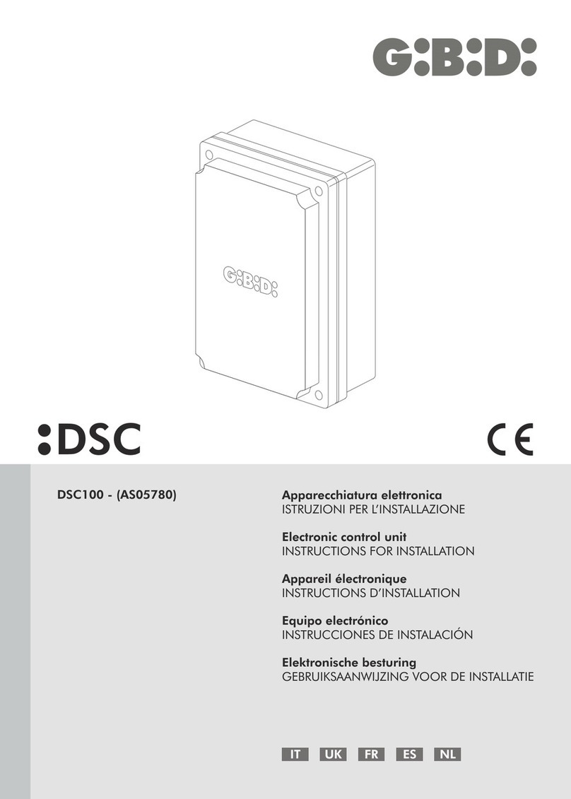
SC130
F E
Apparecchiatura elettronica di comando
ISTRUZIONI PER L’INSTALLAZIONE
Electronic control unit
INSTRUCTIONS FOR INSTALLATION
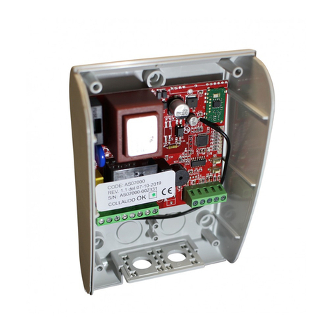
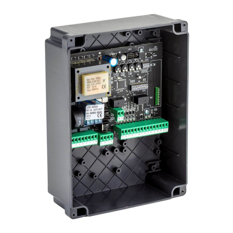
SC130 (AS05920)
Platine électronique de gestion
INSTRUCTIONS POUR L’INSTALLATION
Cuadro electrónico de maniobra
INSTRUCCIONES PARA LA INSTALACIÓN

SC130 SC130
I
CARATTERISTICHE TECNICHESCHEMA ELETTRICO
NOTE PER L’INSTALLAZIONE
Alimentazione 230 VCA monofase 50/60 Hz (F1-5A)
Tempo lavoro Regolabile 7-120sec (JP1 aperto) con trimmer TL
Regolabile 7-40sec (JP1 chiuso) con trimmer TL
N° motori 1 x 500W
Tempo pausa 3-200s con trimmer TP
Tempo luce cortesia Somma tra tempo lavoro e tempo pausa sia dopo Apre che dopo Chiude
Alimentazione fotocellule 12VDc 2W (F2-500mA ripristinabile)
Temperatura d’esercizio -20 +55 °C
Luce cortesia / Lampeggiante 230V 100W
Trasmettitori apprendibili 30
Ricevente trasmettitori Integrata, non sostituibile
Fine corsa Ingressi FCA e FCC in morsettiera
Prima di procedere con l'installazione bisogna predisporre a monte dell'impianto un interruttore magnetotermico e
differenziale con portata massima di 10A. L'interruttore deve garantire una separazione omnipolare dei contatti, con
distanza di apertura di almeno 3 mm.
Differenziare e tenere separati i cavi di potenza (sezione minima 1,5 mmq) dai cavi di segnale che possono essere
da 0,5 mmq.
AVVERTENZE:
• Durante il cablaggio l'apparecchiatura non deve essere alimentata.
• L'impiego di questa apparecchiatura deve seguire e rispettare rigorosamente le norme tecniche di riferimento.
• L'installazione e/o la manutenzione deve essere eseguita solo da personale qualificato nel rispetto delle
disposizioni legislative vigenti.
• Il costruttore non può essere considerato responsabile per eventuali danni causati da uso improprio e/o
irragionevole.
• Una errata installazione o un uso errato del prodotto possono compromettere la sicurezza dell'impianto.
• Tutti i materiali presenti nell'imballo non devono essere lasciati alla portata dei bambini in quanto fonti di pericolo.
ATTENZIONE: IMPORTANTI ISTRUZIONI DI SICUREZZA.
E' importante per la sicurezza delle persone seguire queste istruzioni.
Conservare il presente libretto di istruzioni.
I
2 3
1 2 3456
78 9 10 11 12 13 14 15
PH
NEUT
MOT COM
CLOS
OPEN
LAMP
FCA
FCC
COSTA
PHOTO
COM
UP
DOWN
+12VDC
COM
TL TP
RV3
JP1
P1
SW1
ANT
F1
5A
M
DL1 DL2 DL3 DL4 DL5 DL6
DL7
230 Vac ~ NEUTRAL -
230 Vac ~ PHASE -
ON

I
SC130 SC130
I
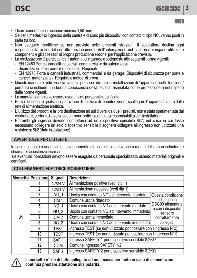
COLLEGAMENTI
DIP SWITCH SW1
TRIMMER
DIP 8 Vedi DIP 6 e 7
DIP 9
DIP 10
DIP 6-7
DIP 5
Ingresso COSTA abilitato come COSTA 8K2 Ingresso COSTA abilitato come COSTA NC
Uscita LAMPEGGIANTE abilitata come
LUCE CORTESIA FISSA (tempo = TL + TP)
Uscita LAMPEGGIANTE abilitata come
LAMPEGGIANTE (tempo = TL)
Abilita LOGICA CONDOMINIALE.
Chiusura automatica sempre abilitata.
Funzionamento in risposta al comando di START:
• Cancello chiuso: APRE.
• Durante l'apertura: ININFLUENTE.
• Cancello aperto: RICARICA TP.
• Durante la chiusura: APRE.
Vedi LOGICHE DI FUNZIONAMENTO
RALLENTAMENTO disabilitato
RALLENTAMENTO abilitato.
Dopo intervento del finecorsa il moto prosegue
per 1s in rallentamento.
DIP
DIP 1
DIP 2
DIP 3
DIP 4
ON
Ingresso COSTA disabilitato
Ingresso FINE CORSA APRE disabilitato Ingresso FINE CORSA APRE abilitato
Ingresso FINE CORSA CHIUDE disabilitato Ingresso FINE CORSA CHIUDE abilitato
Ingresso FOTOCELLULA disabilitato Ingresso FOTOCELLULA abilitato
OFF
Ingresso COSTA abilitato
Trimmer
TL
TP
FV3
(su modulo
a innesto)
Descrizione
Tempo Lavoro
Tempo Pausa Regolazione 3 – 200s.
Ruotando in senso orario il tempo pausa aumenta.
Forza
Ruotando il trimmer sul MODULO FORZA in senso antiorario si aumenta la
forza in chiusura, a ogni partenza si ha comunque uno spunto di 2 secondi
a forza massima.
In apertura la forza è sempre massima per tutta la corsa e non è regolabile.
Funzionamento
Con jumper JP1 APERTO TL = 7-120s.
Con jumper JP1 CHIUSO (default) TL = 7-40s.
Ruotando in senso orario il tempo di lavoro aumenta.
Morsetto
7-8
10
9
1
14
15
13
6
2
3
4
11
5
12
Sigla
FCA-FCC
PHOTO
COSTA
PH
12VDC
COM
ANT
DOWN
LAMP
NEUT
MOT COM
CLOS
COM
OPEN
UP
Descrizione
Fine Corsa APRE-CHIUDE (N.C.)
Ingresso Fotocellula (N.C.)
Ingresso Costa NC/8K2 (vedi DIP9)
Ingresso linea 230 Vac FASE
12 Vdc per alimentazione
ACCESSORI
Comune Ingressi-Uscite Accessori
ANIMA ANTENNA
(filo saldato su circuito)
Ingresso PEDONALE (N.O.)
Luce cortesia / Lampeggiante
Ingresso linea 230 Vac NEUTRO
COMUNE Motore
CHIUDE Motore
Comune Ingressi-Uscite Accessori
APRE Motore
Ingresso START (N.O.)
Funzionamento
Fermano il moto in APRE E CHIUDE o
definiscono l'inizio rallentamento (vedi DIP 5).
Se non utilizzati impostare DIP 2 e 3 in ON.
Se non utilizzata mettere DIP4 in ON.
In APRE ininfluente.
IN CHIUDE riapre.
Se non utilizzata impostare DIP1 in ON e DIP 9
in OFF.
In APERTURA ferma e libera l'ostacolo per
2 secondi.
In CHIUSURA riapre.
In PAUSA funziona come STOP e annulla
richiusura automatica.
Protetto con F1 5A.
Protetto da F2 500mA ripristinabile.
Il cancello apre per 7 secondi. Uno START fa
aprire tutto e interdice il pedonale.
Collegare il lampeggiante o la luce di cortesia
tra NEUT e LAMP (morsetti 2-6) e impostare
il DIP10 di conseguenza.
Se si utilizza la luce di cortesia, collegare il
lampeggiante (con circuito di lampeggio proprio)
tra MOT COM e CLOS (morsetti 3-4).
4 5
OFF OFF PASSO PASSO
CON STOP
Chiusura automatica disabilitata.
Funzionamento in risposta al comando
di START:
• Cancello chiuso: APRE.
• Durante l'apertura: STOP.
• Cancello aperto: CHIUDE.
• Durante la chiusura: STOP.
• Dopo uno STOP: è necessario
un comando e il moto riparte in
direzione opposta rispetto al moto
precedente.
Chiusura automatica disabilitata.
Funzionamento in risposta al comando
PEDONALE:
• Cancello chiuso: APRE per 7s.
• Durante l'apertura: STOP.
• Cancello aperto: CHIUDE.
• Durante la chiusura: STOP.
• Dopo uno STOP: è necessario
un comando e il moto riparte in
direzione opposta rispetto al moto
precedente.
DIP 6 DIP 7 Logica START PEDONALE
LOGICHE DI FUNZIONAMENTO
ON OFF UOMO
PRESENTE
Se mantenuto premuto pulsante:
APRE/CHIUDE
Se mantenuto premuto pulsante:
PEDONALE

I
SC130 SC130
I
TEST
MANOVRA PEDONALE
APPRENDIMENTO TRASMETTITORI
Premere per 2 secondi il tasto P1 all’accensione, la centrale parte in APRE.
Raggiunto il finecorsa di APRE riparte in CHIUDE. Raggiunto il finecorsa di CHIUDE si arresta.
Così si è verificato il corretto funzionamento centrale/motore.
Con 2° tasto appreso del trasmettitore o DOWN da morsettiera il cancello apre per 7 secondi, uno START fa aprire
tutto e interdice il pedonale.
Premere il tasto P1, la centrale entrerà in APPRENDIMENTO (il led lampeggia e poi si accende fisso), premere i tasti
del trasmettitore da memorizzare:
• Al primo tasto premuto, di un nuovo trasmettitore, sarà assegnata la funzione di START.
• Al secondo tasto premuto, dello stesso trasmettitore, sarà assegnata la funzione PEDONALE.
E' possibile memorizzare in sequenza nuovi trasmettitori fino a che il led è acceso fisso.
Dopo l'apprendimento dell'ultimo trasmettitore, occorre attendere lo spegnimento del led (3s) ad indicare che il
sistema è pronto per funzionare in modo normale.
ATTENZIONE: dopo aver appreso il primo trasmettitore, il sistema accetterà soltanto quella famiglia di codici (se il
primo è Rolling tutti gli altri dovranno essere Rolling). Sono apprendibili 30 trasmettitori, al 31° il led lampeggia per
indicare memoria piena.
CANCELLAZIONE TOTALE MEMORIA TRASMETTITORI: premere il pulsante P1 (il led lampeggia e poi si
accende) e mantenerlo premuto sino a quando il led lampeggerà di nuovo e si spegnerà (10s). Al rilascio del pulsante
il led si riaccende indicando che il sistema è pronto per apprendere un nuovo un trasmettitore.
APPRENDIMENTO TRASMETTITORI SENZA ACCEDERE ALLA CENTRALE (TRASMETTITORI ROLLING):
Premere contemporaneamente per 1s i tasti UP e DOWN della morsettiera o contemporaneamente per 2s i tasti 1 e
2 di un trasmettitore già memorizzato. La centrale entrerà in APPRENDIMENTO e sarà possibile seguire la normale
procedura per memorizzare nuovi trasmettitori.
6 7
SMALTIMENTO
GI.BI.DI. consiglia di riciclare i componenti in plastica e di smaltire in appositi centri abilitati i
componenti elettronici evitando di contaminare l'ambiente con sostanze inquinanti.
ON ON
PASSO-PASSO
CON PAUSA
IN APERTURA,
INVERSIONE
IN CHIUSURA
E CHIUSURA
AUTOMATICA
Chiusura automatica abilitata.
Funzionamento in risposta al
comando di START:
• Cancello chiuso: APRE.
• Durante l'apertura: PAUSA,
il cancello si ferma e parte il timer
della chiusura automatica.
• Cancello aperto: CHIUDE.
• Durante la chiusura: Inverte il moto.
Chiusura automatica abilitata
(se DIP8=OFF).
Funzionamento in risposta al comando
PEDONALE:
• Cancello chiuso: APRE per 7s.
• Durante l'apertura: PAUSA
(se DIP8 = OFF), il cancello si
ferma e parte il timer della chiusura
automatica. STOP (se DIP8 = ON).
• Cancello aperto: CHIUDE.
• Durante la chiusura: STOP.
• Dopo uno STOP: è necessario
un comando e il moto riparte in
direzione opposta rispetto al moto
precedente.
Dichiarazione di conformità CE
Il fabbricante:
GI.BI.DI. S.r.l.
Via Abetone Brennero, 177/B,
46025 Poggio Rusco (MN) ITALY
dichiara che il prodotto:
APPARECCHIATURA ELETTRONICA SC130
è conforme alle seguenti Direttive CEE:
e che sono state applicate le seguenti norme armonizzate:
• Direttiva LVD 2006/95CE e successive modifiche
• Direttiva EMC 2004/108/CE e successive modifiche
• EN60335-1
• EN 61000-6-2, EN 61000-6-3
Il Rappresentante Legale
Michele Prandi
OFF ON
PASSO PASSO
CON STOP
E CHIUSURA
AUTOMATICA
Chiusura automatica abilitata.
Funzionamento in risposta al comando
di START:
• Cancello chiuso: APRE.
• Durante l'apertura: STOP.
• Cancello aperto: STOP.
• Durante la chiusura: STOP.
• Dopo uno STOP: è necessario
un comando e il moto riparte in
direzione opposta rispetto al moto
precedente.
Chiusura automatica disabilitata.
Funzionamento in risposta al comando
PEDONALE:
• Cancello chiuso: APRE per 7s.
• Durante l'apertura: STOP.
• Cancello aperto: CHIUDE.
• Durante la chiusura: STOP.
• Dopo uno STOP: è necessario
un comando e il moto riparte in
direzione opposta rispetto al moto
precedente
Data 15/06/2017

I
SC130 SC130
I
TEST
MANOVRA PEDONALE
APPRENDIMENTO TRASMETTITORI
Premere per 2 secondi il tasto P1 all’accensione, la centrale parte in APRE.
Raggiunto il finecorsa di APRE riparte in CHIUDE. Raggiunto il finecorsa di CHIUDE si arresta.
Così si è verificato il corretto funzionamento centrale/motore.
Con 2° tasto appreso del trasmettitore o DOWN da morsettiera il cancello apre per 7 secondi, uno START fa aprire
tutto e interdice il pedonale.
Premere il tasto P1, la centrale entrerà in APPRENDIMENTO (il led lampeggia e poi si accende fisso), premere i tasti
del trasmettitore da memorizzare:
• Al primo tasto premuto, di un nuovo trasmettitore, sarà assegnata la funzione di START.
• Al secondo tasto premuto, dello stesso trasmettitore, sarà assegnata la funzione PEDONALE.
E' possibile memorizzare in sequenza nuovi trasmettitori fino a che il led è acceso fisso.
Dopo l'apprendimento dell'ultimo trasmettitore, occorre attendere lo spegnimento del led (3s) ad indicare che il
sistema è pronto per funzionare in modo normale.
ATTENZIONE: dopo aver appreso il primo trasmettitore, il sistema accetterà soltanto quella famiglia di codici (se il
primo è Rolling tutti gli altri dovranno essere Rolling). Sono apprendibili 30 trasmettitori, al 31° il led lampeggia per
indicare memoria piena.
CANCELLAZIONE TOTALE MEMORIA TRASMETTITORI: premere il pulsante P1 (il led lampeggia e poi si
accende) e mantenerlo premuto sino a quando il led lampeggerà di nuovo e si spegnerà (10s). Al rilascio del pulsante
il led si riaccende indicando che il sistema è pronto per apprendere un nuovo un trasmettitore.
APPRENDIMENTO TRASMETTITORI SENZA ACCEDERE ALLA CENTRALE (TRASMETTITORI ROLLING):
Premere contemporaneamente per 1s i tasti UP e DOWN della morsettiera o contemporaneamente per 2s i tasti 1 e
2 di un trasmettitore già memorizzato. La centrale entrerà in APPRENDIMENTO e sarà possibile seguire la normale
procedura per memorizzare nuovi trasmettitori.
6 7
SMALTIMENTO
GI.BI.DI. consiglia di riciclare i componenti in plastica e di smaltire in appositi centri abilitati i
componenti elettronici evitando di contaminare l'ambiente con sostanze inquinanti.
ON ON
PASSO-PASSO
CON PAUSA
IN APERTURA,
INVERSIONE
IN CHIUSURA
E CHIUSURA
AUTOMATICA
Chiusura automatica abilitata.
Funzionamento in risposta al
comando di START:
• Cancello chiuso: APRE.
• Durante l'apertura: PAUSA,
il cancello si ferma e parte il timer
della chiusura automatica.
• Cancello aperto: CHIUDE.
• Durante la chiusura: Inverte il moto.
Chiusura automatica abilitata
(se DIP8=OFF).
Funzionamento in risposta al comando
PEDONALE:
• Cancello chiuso: APRE per 7s.
• Durante l'apertura: PAUSA
(se DIP8 = OFF), il cancello si
ferma e parte il timer della chiusura
automatica. STOP (se DIP8 = ON).
• Cancello aperto: CHIUDE.
• Durante la chiusura: STOP.
• Dopo uno STOP: è necessario
un comando e il moto riparte in
direzione opposta rispetto al moto
precedente.
Dichiarazione di conformità CE
Il fabbricante:
GI.BI.DI. S.r.l.
Via Abetone Brennero, 177/B,
46025 Poggio Rusco (MN) ITALY
dichiara che il prodotto:
APPARECCHIATURA ELETTRONICA SC130
è conforme alle seguenti Direttive CEE:
e che sono state applicate le seguenti norme armonizzate:
• Direttiva LVD 2006/95CE e successive modifiche
• Direttiva EMC 2004/108/CE e successive modifiche
• EN60335-1
• EN 61000-6-2, EN 61000-6-3
Il Rappresentante Legale
Michele Prandi
OFF ON
PASSO PASSO
CON STOP
E CHIUSURA
AUTOMATICA
Chiusura automatica abilitata.
Funzionamento in risposta al comando
di START:
• Cancello chiuso: APRE.
• Durante l'apertura: STOP.
• Cancello aperto: STOP.
• Durante la chiusura: STOP.
• Dopo uno STOP: è necessario
un comando e il moto riparte in
direzione opposta rispetto al moto
precedente.
Chiusura automatica disabilitata.
Funzionamento in risposta al comando
PEDONALE:
• Cancello chiuso: APRE per 7s.
• Durante l'apertura: STOP.
• Cancello aperto: CHIUDE.
• Durante la chiusura: STOP.
• Dopo uno STOP: è necessario
un comando e il moto riparte in
direzione opposta rispetto al moto
precedente
Data 15/06/2017

SC130 SC130
8 9
UK UK
ELECTRICAL DIAGRAM
1 2 3456
78 9 10 11 12 13 14 15
PH
NEUT
MOT COM
CLOS
OPEN
LAMP
FCA
FCC
COSTA
PHOTO
COM
UP
DOWN
+12VDC
COM
TL TP
RV3
JP1
P1
SW1
ANT
F1
5A
M
DL1 DL2 DL3 DL4 DL5 DL6
DL7
230 Vac ~ NEUTRAL -
230 Vac ~ PHASE -
ON
TECHNICAL CHARACTERISTICS
Power supply
Working time
No. of motors
Pause time
Courtesy light time
Photocells power supply
Operating temperature
Courtesy light / Flasher
Learnable transmitters
Transmitters receiver
Limit switch
230 VCA single-phase 50/60 Hz (F1-5A)
Adjustable 7-120s (JP1open) with trimmer TL
Adjustable 7-40s (JP1 close) with trimmer TL
1 x 500W
3-200s with trimmer TP
Sum between working time and pause time both after Open and after Close
12VDc 2W (F2-500mA restorable)
-20 +55 °C
230V 100W
30
Built-in, not replaceable
Inputs FCA and FCC in terminal board
INSTALLATION WARNINGS
Before proceeding with the installation, it is necessary to fit a magneto-thermal and differential switch of 10A max.
upstream of the system. The switch must guarantee an omnipolar separation of the contacts, with an opening
distance of at least 3 mm.
Differentiate and keep the power cables (min. section 1,5mmq) separated from the signal cables, that can
be 0,5mmq.
WARNINGS:
• During wiring, the control unit must not be powered.
• The use of this control unit must follow and strictly respect the technical standards of reference.
• The installation and/or maintenance must be carried out only by qualified personnel, in compliance with regulations
in force.
• The manufacturer cannot be considered responsible for possible damages caused by improper and/or
unreasonable use.
• A wrong installation or use of the product can compromise the safety of the system.
• All the materials contained in the package must be kept away from children, since they pose a potential risk.
WARNING: IMPORTANT SAFETY INSTRUCTIONS.
It is important for the safety of persons to follow these instructions.
Keep this instruction manual.

UK
SC130 SC130
UK
10 11
CONNECTIONS
Terminal
7-8
10
9
1
14
15
13
6
2
3
4
11
5
12
Abbrev.
FCA-FCC
PHOTO
COSTA
PH
12VDC
COM
ANT
DOWN
LAMP
NEUT
MOT COM
CLOS
COM
OPEN
UP
Description
OPEN-CLOSE (N.C.) Limit Switch
Photocell Input (N.C.)
Frame NC/8K2 Input (see DIP9)
12 Vdc for ACCESSORIES
power supply
Accessories Inputs-Outputs Common
ANTENNA CORE
(wire solded on circuit)
PEDESTRIAN Input (N.O.)
Courtesy light / Flashing light
Accessories Inputs-Outputs Common
START Input (N.O.)
Operation
Stop the motion in OPEN AND CLOSE or define
the beginning of the deceleration (see DIP 5).
If not used, set DIP 2 and 3 in ON.
If not used, put DIP4 in ON.
In OPEN irrelevant.
In CLOSE opens again.
If not used, set DIP1 in ON and DIP 9 in OFF.
In OPENING stops and releases the obstacle
for 2 s.
In CLOSING opens again.
In PAUSE operates as STOP and cancels the
automatic reclosing.
Protected by F1 5A.
Protected by F2 500mA resettable.
The gate opens for 7 s. A START makes open all
and interdicts the pedestrian.
Connect the flashing light or the courtesy light
between NEUT and LAMP (terminals 2-6) and
consequently set the DIP10.
If you use the courtesy light, connect the
flashing light (with its flashing circuit) between
MOT COM and CLOS (terminals 3-4).
Line 230Vac PHASE Input
Line 230Vac NEUTRAL Input
Motor COMMON
Motor CLOSE
Motor OPEN
DIP SWITCH SW1
DIP 5 DECELERATION disabled
DECELERATION enabled.
After the intervention of the limit switch, the motion
goes on for 1s in deceleration.
DIP
DIP 1
DIP 2
DIP 3
DIP 4
ON
FRAME Input disabled
OPENING LIMIT SWITCH Input disabled OPENING LIMIT SWITCH Input enabled
CLOSING LIMIT SWITCH Input disabled CLOSING LIMIT SWITCH Input enabled
PHOTOCELL Input disabled PHOTOCELL Input enabled
OFF
FRAME Input enabled
DIP 8 See DIP 6 and 7
DIP 9
DIP 10
DIP 6-7
FRAME Input enabled as FRAME 8K2 FRAME Input enabled as FRAME NC
FLASHING LIGHT Output enabled as
FIXED COURTESY LIGHT (time = TL + TP)
FLASHING LIGHT Output enabled as
FLASHING LIGHT (time = TL)
Enables CONDOMINIUM LOGIC.
Automatic closing always enabled.
Operation in reply to START command:
• Gate close: OPEN.
• During opening: IRRELEVANT.
• Gate open: CHARGE TP AGAIN.
• During closing: OPEN.
See OPERATION LOGICS
TRIMMER
Trimmer
TL
TP
FV3
(on plug-in
module)
Description
Working Time
Pause Time Adjustment 3 – 200s.
Turning clockwise, the pause time increases.
Force
Turning the trimmer anticlockwise on FORCE MODULE, force in closing is
increased, at every start there is is anyway an acceleration of 2 s at max. force.
In opening the force is always max. for the complete stroke and it is not
adjustable.
Operation
With jumper JP1 OPEN TL=7-120s.
With jumper JP1 CLOSE (default) TL=7-40s.
Turning clockwise, the working time increases.
OFF OFF STEP-BY-STEP
WITH STOP
Automatic closing disabled.
Operation in reply to a START
command:
• Gate close: OPEN.
• During opening: STOP.
• Gate open: CLOSE.
• During closing: STOP.
• After a STOP: It is necessary
a command and the motion starts
again in the opposite direction of
the previous motion.
Automatic closing disabled.
Operation in reply to a PEDESTRIAN
command:
• Gate close: OPEN for 7s.
• During opening: STOP.
• Gate open: CLOSE.
• During closing: STOP.
• After a STOP: It is necessary
a command and the motion starts
again in the opposite direction of
the previous motion.
DIP 6 DIP 7 Logic START PEDESTRIAN
OPERATION LOGICS
ON OFF DEAD MAN If you keep pushed the button:
OPEN/CLOSE
If you keep pushed the button:
PEDESTRIAN

UK
SC130 SC130
UK
12 13
CE Declaration of conformity
The manufacturer:
GI.BI.DI. S.r.l.
Via Abetone Brennero, 177/B,
46025 Poggio Rusco (MN) ITALY
declares that the product:
ELECTRONIC CONTROL UNIT SC130
is in conformity with the following EEC Directives:
and that the following harmonised standards have been applied:
• LVD Directive 2006/95/CE and subsequent amendments
• EMC Directive 2004/108/CE and subsequent amendments
• EN60335-1
• EN 61000-6-2, EN 61000-6-3
The Legal Representative
Michele Prandi
Date 15/06/2017
ON ON
STEP-BY-STEP
WITH PAUSE
IN OPENING,
INVERSION
IN CLOSING
AND
AUTOMATIC
CLOSING
Automatic closing enabled
(if DIP8=OFF).
Operation in reply to a PEDESTRIAN
command:
• Gate close: OPEN for 7s.
• During opening: PAUSE
(if DIP8=OFF), the gate stops and the
timer of the automatic closing starts.
STOP (if DIP8=ON).
• Gate open: CLOSE.
• During closing: STOP.
• After a STOP: It is necessary
a command and the motion starts
again in the opposite direction
of the previous motion.
OFF ON
STEP-BY-STEP
WITH STOP
AND
AUTOMATIC
CLOSING
Automatic closing enabled.
Operation in reply to a START
command:
• Gate close: OPEN.
• During opening: STOP.
• Gate open: STOP.
• During closing: STOP.
• After a STOP: It is necessary
a command and the motion starts
again in the opposite direction
of the previous motion.
Automatic closing disabled.
Operation in reply to a PEDESTRIAN
command:
• Gate close: OPEN for 7s.
• During opening: STOP.
• Gate open: CLOSE.
• During closing: STOP.
• After a STOP: It is necessary
a command and the motion starts
again in the opposite direction
of the previous motion.
Automatic closing enabled.
Operation in reply to a START
command:
• Gate close: OPEN.
• During opening: PAUSE,
the gate stops and the timer of the
automatic closing starts.
• Gate open: CLOSE.
• During closing: Inverts the motion.
TEST
TRANSMITTERS LEARNING
Push the button P1 for 2 s when you turn it on, the control unit starts in OPEN.
Once reached the OPENING limit switch starts again in CLOSING. Once reached the CLOSING limit switch it stops.
In this way you have the correct control unit/motor operation.
Push the button P1, the control unit will enter in LEARNING (the led blinks, then turns on fixed), push the buttons
of the transmitter to store:
• START function will be assigned to the first button pushed of a new transmitter.
• PEDESTRIAN function will be assigned to the second button pushed of the same transmitter.
It is possible to store in sequence some new transmitters as long as the led is turned off fixed.
After the learning of last transmitter, it is necessary to wait that led turns off (3s), indicating the system is ready to work
in a normal way.
WARNING: After learning the first transmitter, the system will accept only that family of codes (if the first one
is Rolling, all the transmitters must be Rolling). It can learn 30 transmitters, when you arrive to the 31st the led blinks
because the memory is full.
PEDESTRIAN MANOEUVRE
With the 2nd button learned by the transmitter or DOWN from terminal board, the gate opens for 7 s, a START makes
open all and denies the pedestrian.
COMPLETE CANCELLATION OF TRANSMITTERS MEMORY: Push the button P1 (the led blinks, then turns on)
and keep it pushed as long as the led will blink again and turn off (10s). When you release the button, the led turns on
again, indicating that the system is ready to learn a new transmitter.
LEARNING OF TRANSMITTERS WITHOUT ACCEDING TO THE CONTROL UNIT (ROLLING
TRANSMITTERS): Push the buttons UP and DOWN of the terminal board at the same time for 1 s or the buttons
1 and 2 of a transmitter already stored at the same time for 2 s. The control unit will enter in LEARNING and it will be
possible to follow the usual procedure to store the new transmitters.
DISPOSAL
GI.BI.DI. advises recycling the plastic components and to dispose of them at special authorised
centres for electronic components thus protecting the environment from polluting substances.

UK
SC130 SC130
UK
12 13
CE Declaration of conformity
The manufacturer:
GI.BI.DI. S.r.l.
Via Abetone Brennero, 177/B,
46025 Poggio Rusco (MN) ITALY
declares that the product:
ELECTRONIC CONTROL UNIT SC130
is in conformity with the following EEC Directives:
and that the following harmonised standards have been applied:
• LVD Directive 2006/95/CE and subsequent amendments
• EMC Directive 2004/108/CE and subsequent amendments
• EN60335-1
• EN 61000-6-2, EN 61000-6-3
The Legal Representative
Michele Prandi
Date 15/06/2017
ON ON
STEP-BY-STEP
WITH PAUSE
IN OPENING,
INVERSION
IN CLOSING
AND
AUTOMATIC
CLOSING
Automatic closing enabled
(if DIP8=OFF).
Operation in reply to a PEDESTRIAN
command:
• Gate close: OPEN for 7s.
• During opening: PAUSE
(if DIP8=OFF), the gate stops and the
timer of the automatic closing starts.
STOP (if DIP8=ON).
• Gate open: CLOSE.
• During closing: STOP.
• After a STOP: It is necessary
a command and the motion starts
again in the opposite direction
of the previous motion.
OFF ON
STEP-BY-STEP
WITH STOP
AND
AUTOMATIC
CLOSING
Automatic closing enabled.
Operation in reply to a START
command:
• Gate close: OPEN.
• During opening: STOP.
• Gate open: STOP.
• During closing: STOP.
• After a STOP: It is necessary
a command and the motion starts
again in the opposite direction
of the previous motion.
Automatic closing disabled.
Operation in reply to a PEDESTRIAN
command:
• Gate close: OPEN for 7s.
• During opening: STOP.
• Gate open: CLOSE.
• During closing: STOP.
• After a STOP: It is necessary
a command and the motion starts
again in the opposite direction
of the previous motion.
Automatic closing enabled.
Operation in reply to a START
command:
• Gate close: OPEN.
• During opening: PAUSE,
the gate stops and the timer of the
automatic closing starts.
• Gate open: CLOSE.
• During closing: Inverts the motion.
TEST
TRANSMITTERS LEARNING
Push the button P1 for 2 s when you turn it on, the control unit starts in OPEN.
Once reached the OPENING limit switch starts again in CLOSING. Once reached the CLOSING limit switch it stops.
In this way you have the correct control unit/motor operation.
Push the button P1, the control unit will enter in LEARNING (the led blinks, then turns on fixed), push the buttons
of the transmitter to store:
• START function will be assigned to the first button pushed of a new transmitter.
• PEDESTRIAN function will be assigned to the second button pushed of the same transmitter.
It is possible to store in sequence some new transmitters as long as the led is turned off fixed.
After the learning of last transmitter, it is necessary to wait that led turns off (3s), indicating the system is ready to work
in a normal way.
WARNING: After learning the first transmitter, the system will accept only that family of codes (if the first one
is Rolling, all the transmitters must be Rolling). It can learn 30 transmitters, when you arrive to the 31st the led blinks
because the memory is full.
PEDESTRIAN MANOEUVRE
With the 2nd button learned by the transmitter or DOWN from terminal board, the gate opens for 7 s, a START makes
open all and denies the pedestrian.
COMPLETE CANCELLATION OF TRANSMITTERS MEMORY: Push the button P1 (the led blinks, then turns on)
and keep it pushed as long as the led will blink again and turn off (10s). When you release the button, the led turns on
again, indicating that the system is ready to learn a new transmitter.
LEARNING OF TRANSMITTERS WITHOUT ACCEDING TO THE CONTROL UNIT (ROLLING
TRANSMITTERS): Push the buttons UP and DOWN of the terminal board at the same time for 1 s or the buttons
1 and 2 of a transmitter already stored at the same time for 2 s. The control unit will enter in LEARNING and it will be
possible to follow the usual procedure to store the new transmitters.
DISPOSAL
GI.BI.DI. advises recycling the plastic components and to dispose of them at special authorised
centres for electronic components thus protecting the environment from polluting substances.

SC130 SC130
14 15
F F
SCHÉMA DE CABLAGE
1 2 3456
78 9 10 11 12 13 14 15
PH
NEUT
MOT COM
CLOS
OPEN
LAMP
FCA
FCC
COSTA
PHOTO
COM
UP
DOWN
+12VDC
COM
TL TP
RV3
JP1
P1
SW1
ANT
F1
5A
M
DL1 DL2 DL3 DL4 DL5 DL6
DL7
230 Vac ~ NEUTRAL -
230 Vac ~ PHASE -
ON
ATTENTION: INSTRUCTIONS DE SÉCURITÉ IMPORTANTES.
Pour la sécurité des personnes, veiller au respect des présentes instructions.
Conserver le présent manuel des instructions.
CARACTERISTIQUES TECHNIQUES
Alimentation
Temps de service
No. of moteurs
Temps de pause
Temps lampe témoin
Alimentation Photocellules
Température de service
Lampe témoin / Feu Clignotant
Emetteurs qui peuvent être appris
Récepteur emetteurs
Fin de Course
230 VCA monophasé 50/60 Hz (F1-5A)
Réglable 7-120 s (JP1 ouvert) avec trimmer TL
Réglable 7-40 s (JP1 fermé) avec trimmer TL
1 x 500W
3-200s avec trimmer TP
Somme entre temps de service et temps de pause
tant après Ouvre qu'après Ferme
12VDc 2W (F2-500mA restorable)
-20 +55 °C
230V 100W
30
Intégrée, pas remplaçable
Entrées FCA et FCC dans la boîte à bornes
NOTES POUR L'INSTALLATION
Avant d'effectuer la mise en place, il faut prévoir en amont de l'installation un interrupteur magnétique-thermique
et différentiel ayant une capacité maxi de 10A. L'interrupteur doit assurer une séparation omnipolaire des contacts,
avec une distance d'ouverture d'au moins 3 mm.
Différencier et toujours maintenir séparés les câbles de puissance (section mini. 1,5mmq) des câbles de signal, qui
peuvent être de 0,5mmq.
AVERTISSEMENTS:
• Pendant le câblage, l'appareil électronique ne doit pas être alimenté.
• L'utilisation de cet appareil doit suivre et respecter rigoureusement les normes techniques de référence.
• L'installation et/ou l'entretien doit être effectuée seulement par un personnel qualifié, respectant les dispositions
législatives en vigueur.
• Le constructeur ne peut pas être considéré responsable pour éventuels dommages causés par une utilisation
impropre et/ou irraisonnable.
• Une mauvaise installation ou utilisation du produit peut compromettre la sécurité de l'installation,
• Tous les matériaux présents dans l'emballage ne doivent pas être laissés à la portée des enfants, car il peuvent
être dangereux.

SC130 SC130
16 17
F F
BRANCHEMENTS
Borne
7-8
10
9
1
14
15
13
6
2
3
4
11
5
12
FCA-FCC
PHOTO
COSTA
PH
12VDC
COM
ANT
DOWN
LAMP
NEUT
MOT COM
CLOS
COM
OPEN
UP
Description
Fins de course ABRE-FERME (N.C.)
Entrée Photocellule (N.C.)
Entrée Bord NC/8K2 (voir DIP9)
Entrée ligne 230Vac PHASE
12 Vdc pour alimentation
ACCESSOIRES
Commun Entrées-Sorties Accessoires
AME ANTENNE
(fil soudé sur circuit)
Entrée PIETON (N.O.)
Lampe temoin / Feu clignotant
Entrée ligne 230 Vac NEUTRE
COMMUN moteur
FERME moteur
Commun s-Sorties AccessoiresEntrée
OUVRE moteur
Entrée START (N.O.)
Fonctionnement
Arrêtent le mouvement en OUVRE ET FERME ou
définissent le début du ralentissement (voir DIP 5).
Si pas utilisés, poser DIP 2 et 3 en ON.
Si pas utilisée, mettre DIP4 en ON.
En OUVRE pas influente.
EN FERME ouvre de nouveau.
Si pas utilisée, poser DIP1 en ON et DIP 9
en OFF.
En OUVERTURE arrêt et libre l'obstacle par 2 s.
En FERMETURE ouvre de nouveau.
En PAUSE marche comme STOP et annule la
nouvelle fermeture automatique.
Protégé avec F1 5A.
Protégé par F2 500mA qu’on peut restaurer.
Le portail ouvre par 7 s.
Un START fait ouvrir tout et interdit le piéton.
Brancher le feu clignotant ou la lampe témoin
entre NEUT et LAMP (bornes 2-6) et par suite
poser le DIP10.
Si on utilise la lampe témoin, brancher le feu
clignotant (avec son circuit de clignotement)
entre MOT COM et CLOS (bornes 3-4).
Abrév.
DIP SWITCH SW1
DIP 5 RALENTISSEMENT désactivé
RALENTISSEMENT ACTIVE.
Après l'intervention du fin de course, le mouvement
continue par 1s en ralentissement.
DIP
DIP 1
DIP 2
DIP 3
DIP 4
ON
Entrée BORD désactivée
Entrée désactivée FIN DE COURSE OUVRE Entrée FIN DE COURSE OUVRE activée
Entrée FIN DE COURSE FERME désactivée Entrée FIN DE COURSE FERME activée
Entrée PHOTOCELLULE désactivée Entrée PHOTOCELLULE activée
OFF
Entrée BORD activée
DIP 8 Voir DIP 6 et 7
DIP 9
DIP 10
DIP 6-7
Entrée BORD activée comme BORD 8K2 Entrée BORD activée comme BORD NC
Sortie FEU CLIGNOTANT
LAMPE TEMOIN FIXE (temps = TL + TP)
activée comme Sortie FEU CLIGNOTANT activée comme
FEU CLIGNOTANT (temps = TL)
ACTIVE LOGIQUE DE COPROPRIETEE.
Fermeture automatique toujours activée.
Fonctionnement en repos à la commande de START:
• Portail fermé: OUVRE.
• Pendant l'ouverture: PAS INFLUENT.
• Portail ouvert: RECHARGE TP.
• Pendant la fermeture: OUVRE.
Voir LOGIQUES DE FONCTIONNEMENT
TRIMMER
Trimmer
TL
TP
FV3
(sur module
à enclenche-
ment)
Description
Temps de Service
Temps de Pause Réglage 3 – 200s.
Tournant dans le sens horaire, le temps de pause augmente.
Force
Tournant le trimmer sur le MODULE FORCE dans le sens antihoraire, on
augmente la force en fermeture, à chaque départ, on a de toute façon une pointe
de 2 s à force maxi.
En ouverture la force est toujours maxi par toute la course et n'est pas réglable.
Fonctionnement
Avec jumper JP1 OUVERT TL = 7-120s.
Avec jumper JP1 FERME (défaut) TL = 7-40s.
Tournant dans le sens horaire, le temps de service augmente.
OFF OFF PAS-PAS
AVEC STOP
Fermeture automatique désactivée.
Fonctionnement en réponse à la
commande de START:
• Portail fermé: OUVRE.
• Pendant l'ouverture: STOP.
• Portail ouvert: FERME.
• Pendant la fermeture: STOP.
• Après un STOP: il faut une
commande et le mouvement part de
nouveau dans la direction opposée
au mouvement précédent.
Fermeture automatique désactivée.
Fonctionnement en réponse à la
commande PIETON:
• Portail fermé: OUVRE par 7s.
• Pendant l'ouverture: STOP.
• Portail ouvert: FERME.
• Pendant la fermeture: STOP.
• Après un STOP: il faut une
commande et le mouvement part de
nouveau dans la direction opposée
au mouvement précédent.
DIP 6 DIP 7 Logique START PIETON
LOGIQUES DE FONCTIONNEMENT
ON OFF HOMME
PRESENT
Si on maintient appuyé sur la touche:
OUVRE/FERME
Si on maintient appuyé sur la touche:
PIETON

SC130 SC130
18 19
F F
Déclaration de conformité CE
Le fabricant:
GI.BI.DI. S.r.l.
Via Abetone Brennero, 177/B,
46025 Poggio Rusco (MN) ITALY
déclare que le produit:
APPAREIL ÉLECTRONIQUE SC130
est en conformité avec les exigences des Directives CEE:
et que les normes harmonisées suivantes ont été appliquées:
• Directive LVD 2006/95CE et ses modifications
• Directive EMC 2004/108/CE et ses modifications
• EN60335-1
• EN 61000-6-2, EN 61000-6-3
Le Représentant Légal
Michele Prandi
Date 15/06/2017
ON ON
PAS-PAS
AVEC PAUSE
EN
OUVERTURE,
INVERSION EN
FERMETURE
ET
FERMETURE
AUTOMATIQUE
Fermeture automatique activée.
Fonctionnement en réponse à la
commande de START:
• Portail fermé: OUVRE.
• Pendant l'ouverture: PAUSE,
le portail s'arrêt et le timer de la
fermeture automatique part.
• Portail ouvert: FERME.
• Pendant la fermeture: Inverse le
mouvement.
Fermeture automatique activée
(si DIP8=OFF).
Fonctionnement en réponse à la
commande PIETON:
• Portail fermé: OUVRE par 7s.
• Pendant l'ouverture: PAUSE
(si DIP8=OFF), le portail s'arrêt et le
timer de la fermeture automatique
part. STOP (si DIP8=ON).
• Portail ouvert: FERME.
• Pendant la fermeture: STOP.
• Après un STOP: il faut une
commande et le mouvement part de
nouveau dans la direction opposée
au mouvement précédent.
OFF ON
PAS-PAS
AVEC STOP
ET FERMETURE
AUTOMATIQUE
Fermeture automatique activée.
Fonctionnement en réponse à la
commande de START:
• Portail fermé: OUVRE.
• Pendant l'ouverture: STOP.
• Portail ouvert: STOP.
• Pendant la fermeture: STOP.
• Après un STOP: il faut une
commande et le mouvement part de
nouveau dans la direction opposée
au mouvement précédent.
Fermeture automatique désactivée.
Fonctionnement en réponse à la
commande PIETON:
• Portail fermé: OUVRE par 7s.
• Pendant l'ouverture: STOP.
• Portail ouvert: FERME.
• Pendant la fermeture: STOP.
• Après un STOP: il faut une
commande et le mouvement part de
nouveau dans la direction opposée
au mouvement précédent.
TEST
APPRENTISSAGE EMETTEURS
Quand on allume la centrale, appuyer sur la touche P1 par 2 s et elle part en OUVRE.
Quand on arrive au fin de course d'OUVRE elle part de nouveau en FERME. Quand on arrive au fin de course
de FERME elle s'arrête.
De cette façon le correct fonctionnement centrale/moteur se vérifie.
Appuyer sur la touche P1, la centrale entrera en APPRENTISSAGE (le led clignote et puis s'allume fixe), appuyer
sur les touches de l'émetteur qu'on doit mémoriser:
• Quand on appuie sur la première touche d'un nouvel émetteur, la fonction de START sera assignée.
• Quand on appuie sur la deuxième touche du même émetteur, la fonction PIETON sera assignée.
Il est possible mémoriser en séquence des nouveaux émetteurs jusqu'à ce que le led est allumé fixe.
Après l'apprentissage du dernier émetteur, il faut attendre que le led s'éteint (3s) à indiquer que le système est
prêt pour fonctionner d'une façon normale.
ATTENTION: Après avoir appris le premier émetteur, le système acceptera seulement cette famille de codes
(si le premier est Rolling, tous les autres doivent être Rolling). On peut apprendre 30 émetteurs, quand on arrive
au 31ème, le led clignote pour indiquer que la mémoire est pleine.
MANOEUVRE PIETON
Avec la 2ème touche apprise par l'émetteur ou DOWN de boîte à bornes, le portail ouvre par 7 s, un START fait
ouvrir tout et interdit le piéton.
EFFACEMENT TOTAL MEMOIRE EMETTEURS: appuyer sur la touche P1 (le led clignote et puis s'allume)
et le maintenir appuyé jusqu'à quand le led clignotera de nouveau et s'éteindra (10s). Quand on relâche la touche,
le led s'allume de nouveau à indiquer que le système est prêt pour apprendre un nouvel émetteur.
APPRENTISSAGE EMETTEURS SANS ACCEDER A LA CENTRALE (EMETTEURS ROLLING): Appuyer
en même temps par 1 s sur les touches UP et DOWN de la boîte à bornes ou par 2s sur les touches 1 et 2
d'un émetteur déjà mémorisé. La centrale entrera en APPRENTISSAGE et il sera possible suivre la normale
procédure pour mémoriser des nouveaux émetteurs.
ELIMINATION
GI.BI.DI. conseille de recycler les composants en plastique et de remettre les composants
électroniques à des centres spécialisés pour éviter de polluer l'environnement avec des
substances polluantes.

SC130 SC130
18 19
F F
Déclaration de conformité CE
Le fabricant:
GI.BI.DI. S.r.l.
Via Abetone Brennero, 177/B,
46025 Poggio Rusco (MN) ITALY
déclare que le produit:
APPAREIL ÉLECTRONIQUE SC130
est en conformité avec les exigences des Directives CEE:
et que les normes harmonisées suivantes ont été appliquées:
• Directive LVD 2006/95CE et ses modifications
• Directive EMC 2004/108/CE et ses modifications
• EN60335-1
• EN 61000-6-2, EN 61000-6-3
Le Représentant Légal
Michele Prandi
Date 15/06/2017
ON ON
PAS-PAS
AVEC PAUSE
EN
OUVERTURE,
INVERSION EN
FERMETURE
ET
FERMETURE
AUTOMATIQUE
Fermeture automatique activée.
Fonctionnement en réponse à la
commande de START:
• Portail fermé: OUVRE.
• Pendant l'ouverture: PAUSE,
le portail s'arrêt et le timer de la
fermeture automatique part.
• Portail ouvert: FERME.
• Pendant la fermeture: Inverse le
mouvement.
Fermeture automatique activée
(si DIP8=OFF).
Fonctionnement en réponse à la
commande PIETON:
• Portail fermé: OUVRE par 7s.
• Pendant l'ouverture: PAUSE
(si DIP8=OFF), le portail s'arrêt et le
timer de la fermeture automatique
part. STOP (si DIP8=ON).
• Portail ouvert: FERME.
• Pendant la fermeture: STOP.
• Après un STOP: il faut une
commande et le mouvement part de
nouveau dans la direction opposée
au mouvement précédent.
OFF ON
PAS-PAS
AVEC STOP
ET FERMETURE
AUTOMATIQUE
Fermeture automatique activée.
Fonctionnement en réponse à la
commande de START:
• Portail fermé: OUVRE.
• Pendant l'ouverture: STOP.
• Portail ouvert: STOP.
• Pendant la fermeture: STOP.
• Après un STOP: il faut une
commande et le mouvement part de
nouveau dans la direction opposée
au mouvement précédent.
Fermeture automatique désactivée.
Fonctionnement en réponse à la
commande PIETON:
• Portail fermé: OUVRE par 7s.
• Pendant l'ouverture: STOP.
• Portail ouvert: FERME.
• Pendant la fermeture: STOP.
• Après un STOP: il faut une
commande et le mouvement part de
nouveau dans la direction opposée
au mouvement précédent.
TEST
APPRENTISSAGE EMETTEURS
Quand on allume la centrale, appuyer sur la touche P1 par 2 s et elle part en OUVRE.
Quand on arrive au fin de course d'OUVRE elle part de nouveau en FERME. Quand on arrive au fin de course
de FERME elle s'arrête.
De cette façon le correct fonctionnement centrale/moteur se vérifie.
Appuyer sur la touche P1, la centrale entrera en APPRENTISSAGE (le led clignote et puis s'allume fixe), appuyer
sur les touches de l'émetteur qu'on doit mémoriser:
• Quand on appuie sur la première touche d'un nouvel émetteur, la fonction de START sera assignée.
• Quand on appuie sur la deuxième touche du même émetteur, la fonction PIETON sera assignée.
Il est possible mémoriser en séquence des nouveaux émetteurs jusqu'à ce que le led est allumé fixe.
Après l'apprentissage du dernier émetteur, il faut attendre que le led s'éteint (3s) à indiquer que le système est
prêt pour fonctionner d'une façon normale.
ATTENTION: Après avoir appris le premier émetteur, le système acceptera seulement cette famille de codes
(si le premier est Rolling, tous les autres doivent être Rolling). On peut apprendre 30 émetteurs, quand on arrive
au 31ème, le led clignote pour indiquer que la mémoire est pleine.
MANOEUVRE PIETON
Avec la 2ème touche apprise par l'émetteur ou DOWN de boîte à bornes, le portail ouvre par 7 s, un START fait
ouvrir tout et interdit le piéton.
EFFACEMENT TOTAL MEMOIRE EMETTEURS: appuyer sur la touche P1 (le led clignote et puis s'allume)
et le maintenir appuyé jusqu'à quand le led clignotera de nouveau et s'éteindra (10s). Quand on relâche la touche,
le led s'allume de nouveau à indiquer que le système est prêt pour apprendre un nouvel émetteur.
APPRENTISSAGE EMETTEURS SANS ACCEDER A LA CENTRALE (EMETTEURS ROLLING): Appuyer
en même temps par 1 s sur les touches UP et DOWN de la boîte à bornes ou par 2s sur les touches 1 et 2
d'un émetteur déjà mémorisé. La centrale entrera en APPRENTISSAGE et il sera possible suivre la normale
procédure pour mémoriser des nouveaux émetteurs.
ELIMINATION
GI.BI.DI. conseille de recycler les composants en plastique et de remettre les composants
électroniques à des centres spécialisés pour éviter de polluer l'environnement avec des
substances polluantes.

SC130 SC130
20 21
E E
ESQUEMA ELÉCTRICO
1 2 3456
78 9 10 11 12 13 14 15
PH
NEUT
MOT COM
CLOS
OPEN
LAMP
FCA
FCC
COSTA
PHOTO
COM
UP
DOWN
+12VDC
COM
TL TP
RV3
JP1
P1
SW1
ANT
F1
5A
M
DL1 DL2 DL3 DL4 DL5 DL6
DL7
230 Vac ~ NEUTRAL -
230 Vac ~ PHASE -
ON
ATENCIÓN: INSTRUCCIONES IMPORTANTES DE SEGURIDAD.
Es importante para la seguridad de las personas seguir estas instrucciones.
Conservar el presente manual de instrucciones.
CARACTERÍSTICAS TÉCNICAS
NOTAS PARA LA INSTALACIÓN
Alimentación 230 VCA monofásica 50/60 Hz (F1-5A)
Tiempo de trabajo Regulable 7-120sec (JP1 abierto) con trimmer TL
Regulable 7-40sec (JP1 cerrado) con trimmer TL
N° motores 1 x 500W
Tiempo de pausa 3-200s con trimmer TP
Tiempo luz interior Suma entre tiempo de trabajo y tiempo de pausa
tanto después Abre como después Cierra
Alimentación fotocélulas 12VDc 2W (F2-500mA que se puede restablecer)
Temperatura de funcionamiento -20 +55 °C
Luz interior / Luz intermitente 230V 100W
Transmisores que se pueden aprender 30
Receptor transmisores Integrado, que no se puede sostitur
Final de carrera Entradas FCA y FCC en tablero de bornes
Antes de proceder a la instalación, hay que preparar aguas arriba de la misma un interruptor magneto-térmico
y diferencial con capacidad máxima de 10A. El interruptor debe garantizar una separación omnipolar de los
contactos, con una distancia de apertura de min. 3 mm.
Distinguir y mantener separados los cables de potencia (sección mínima 1,5mmq) de los cables de señal,
que pueden ser de 0,5mmq.
ADVERTENCIAS:
• Durante el cableo, la central no debe ser alimentada.
• El uso de esta central debe seguir y respetar estrictamente las normas técnicas de referencia.
• La instalación y/o el mantenimiento deben ser hechos sólo por personal cualificado, respetando las disposiciones
legislativas vigentes.
• El fabricante no puede ser considerado responsable para eventuales daños causados por uso impropio y/o irracional.
• Una instalación o utilización incorrecta del producto puede afectar la seguridad del equipo.
• Todo material presente en el embalaje debe mantenerse fuera del alcance de los niños, ya que consituye una
posible fuente de peligro.
.
This manual suits for next models
1
Table of contents
Languages:
Other GiBiDi Control Unit manuals