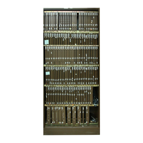
Nortel DMS-100 Series User manual

Critical Release Notice
Publication number: 297-8331-815
Publication release: Standard 10.02
The content of this customer NTP supports the
SN06 (DMS) and ISN06 (TDM) software releases.
Bookmarks used in this NTP highlight the changes between the baseline NTP and the current
release. The bookmarks provided are color-coded to identify release-specific content changes. NTP
volumes that do not contain bookmarks indicate that the baseline remains unchanged and is valid
for the current release.
Bookmark Color Legend
Black: Applies to new or modified content for the baseline NTP that is valid through the
current release.
Red: Applies to new or modified content for NA017/ISN04 (TDM) that is valid through the
current release.
Blue: Applies to new or modified content for NA018 (SN05 DMS)/ISN05 (TDM) that is valid
through the current release.
Green: Applies to new or modified content for SN06 (DMS)/ISN06 (TDM) that is valid
through the current release.
Attention!
Adobe
Acrobat
Reader
5.0 is required to view bookmarks in color.

Publication History
March 2004
Standard release 10.02 for software release SN06 (DMS) and ISN06 (TDM).
Changes in section “Remote Switching Center Multi-access (RSC-M)” due to CR
Q00693785:
• Change of range of FRAME parameter in “Datafilling table GPPTRNSL”
• Additional error message in “Error messages for table GPPTRNSL”
Change of phone number for Nortel Networks documentation support from 1-800-684-2273
to 1-877-662-5669, Option 4 + 1.

XPM12 and up Standard 10.01 August 1999
297-8331-815
DMS-100 Family
Extended Peripheral Module
International Translations Reference Manual


DMS-100 Family XPM International Translations Reference Manual XPM12 and up
DMS-100 Family
Extended Peripheral Module
International Translations Reference Manual
Copyright 1994, 1995, 1996, 1997, 1998, 1999 Nortel Networks,
All Rights Reserved
Printed in the United States of America
NORTEL NETWORKS CONFIDENTIAL: The information contained herein is the property of Nortel Networks and is
strictly confidential. Except as expressly authorized in writing by Nortel Networks, the holder shall keep all information
contained herein confidential, shall disclose the information only to its employees with a need to know, and shall protect the
information, in whole or in part, from disclosure and dissemination to third parties with the same degree of care it uses to
protect its own confidential information, but with no less than reasonable care. Except as expressly authorized in writing by
Nortel Networks, the holder is granted no rights to use the information contained herein.
Information is subject to change without notice. Northern Telecom reserves the right to make changes in design or components
as progress in engineering and manufacturing may warrant.
DMS
,
DMS SuperNode
,
MAP, and
NT are trademarks of Northern Telecom.
Publication number: 297-8331-815
Product release: XPM12 and up
Document release: Standard 10.01
Date: August 1999


DMS-100 Family XPM International Translations Reference Manual XPM12 and up
iii
Contents
About this document vii
When to use this document vii
How to check the version and issue of this document vii
References in this document vii
What precautionary messages mean viii
How commands, parameters, and responses are represented ix
Input prompt (>) ix
Commands and fixed parameters ix
Variables ix
Responses ix
XPM International Translations Introduction 1-1
Introduction to data tables 2-1
Tuple properties 2-1
Using the table editor 2-2
Procedures for datafilling any system 2-3
Input prompts and prompting mode 2-3
Nonprompt mode 2-4
Activating changes to tables 2-4
Table editor commands 2-5
Remote Switching Center-SONET International 3-1
Understanding RSC-S International translations 3-1
Differences between RSC and RSC-S 3-1
Software functionality 3-1
Revised system architecture 3-2
Packaging 3-2
Cabinetized remote switching center (CRSC) cabinet 3-3
CRSC extension (CEXT) cabinet 3-4
Cabinetized line modules (CLCE) 3-5
Cabinetized power distribution center (CPDC) cabinet 3-5
Cabinetized miscellaneous equipment (CMIS) cabinet 3-5
Cabinetized miscellaneous spares storage (CMISS) cabinet 3-5
RSC-S services 3-5
RSC-S configurations 3-6
Preparing to datafill for RSC_S_International 3-9
PCL—New Software Delivery Vehicle 3-9
Collecting end-user data 3-9
Configurations 3-10

iv Contents
297-8331-815 Standard 10.01 August 1999
Activating the RSC-S 3-10
When to update the RCO2 static data 3-10
Alarms produced when a static data mismatch occurs 3-10
Tuple changed (TUPC) logs for static data updates 3-11
Types of TUPC logs 3-11
TUPC log format 3-11
Basic call processing 3-13
ESA lines and trunks 3-107
PCM-30 R1 Trunking 3-126
ISDN operations 3-143
Firmware downloading 3-206
Remote Switching Center-SONET (UK / Europe) 4-1
Understanding RSC-S translations 4-1
Differences between RSC and RSC-S 4-1
Software functionality 4-1
Revised system architecture 4-2
Packaging 4-3
Cabinetized remote switching center (CRSC) cabinet 4-3
CRSC extension (CEXT) cabinet 4-4
Cabinetized line modules (CLCE) cabinet 4-5
Cabinetized power distribution center (CDPC) cabinet 4-6
Cabinetized miscellaneous equipment (CMIS) cabinet 4-6
Cabinetized miscellaneous spare storage (CMSS) cabinet 4-6
RSC-S services 4-6
RSC-S configurations 4-7
Preparing to datafill RSC-S UK/Europe 4-10
PCL—New Software Delivery Vehicle 4-10
Collecting end-user data 4-10
Configurations 4-11
Activating the RSC-S 4-11
When to update the RCO2 static data (SD) 4-11
Alarms produced when an SD mismatch occurs 4-11
Tuple changed (TUPC) logs for static data (SD) updates 4-12
Types of TUPC logs 4-12
TUPC log format 4-12
Basic call processing 4-14
ESA lines and trunks 4-105
PCM-30 R1 Trunking 4-124
ISDN operations 4-142
Firmware downloading 4-193
Introduction to RSC-M 5-1
Understanding RSC-M translations 5-1
Signaling for the RSC-M 5-2
Signaling and communications types 5-2
Preparing to datafill RSC-M 5-4
Functional group for the RSC-M 5-4
Feature set support 5-4
CLASS 5-5
RSC-M call process 5-8

Contents v
DMS-100 Family XPM International Translations Reference Manual XPM12 and up
Updating static data 5-9
Static data update 5-9
Bulk data update 5-11
Dynamic data update 5-12
Remote Switching Center Multi-access (RSC-M) 5-14
Index 6-1


DMS-100 Family XPM International Translations Reference Manual XPM12 and up
vii
About this document
When to use this document
How to check the version and issue of this document
The version and issue of the document are indicated by numbers, for
example, 01.01.
The first two digits indicate the version. The version number increases each
time the document is updated to support a new software release. For
example, the first release of a document is 01.01. In the next software
release cycle, the first release of the same document is 02.01.
The second two digits indicate the issue. The issue number increases each
time the document is revised but rereleased in the same software release
cycle. For example, the second release of a document in the same software
release cycle is 01.02.
To determine which version of this document applies to the software in your
office and how documentation for your product is organized, check the
release information in the DMS-10 and DMS-100 Family Product
Documentation Directory, 297-8991-001.
This document is written for all DMS-100 Family offices. More than one
version of this document may exist. To determine whether you have the
latest version of this document and how documentation for your product is
organized, check the release information in the DMS-10 and DMS-100
Family Product Documentation Directory, 297-8991-001.
References in this document
The following documents are referred to in this document:
•Log Report Reference Manual
•Office Parameters Reference Manual
•Operational Measurements Reference Manual
•Product Documentation Directory, 297-8991-001

viii About this document
297-8331-815 Standard 10.01 August 1999
•SERVORD Reference Manual
•Translations Guide
What precautionary messages mean
The types of precautionary messages used in Nortel Networks documents
include attention boxes and danger, warning, and caution messages.
An attention box identifies information that is necessary for the proper
performance of a procedure or task or the correct interpretation of
information or data. Danger, warning, and caution messages indicate
possible risks.
Examples of the precautionary messages follow.
ATTENTION Information needed to perform a task
ATTENTION
If the unused DS-3 ports are not deprovisioned before a DS-1/VT
Mapper is installed, the DS-1 traffic will not be carried through the
DS-1/VT Mapper, even though the DS-1/VT Mapper is properly
provisioned.
DANGER Possibility of personal injury
DANGER
Risk of electrocution
Do not open the front panel of the inverter unless fuses
F1, F2, and F3 have been removed. The inverter contains
high-voltage lines. Until the fuses are removed, the
high-voltage lines are active, and you risk being
electrocuted.
WARNING Possibility of equipment damage
WARNING
Damage to the backplane connector pins
Align the card before seating it, to avoid bending the
backplane connector pins. Use light thumb pressure to
align the card with the connectors. Next, use the levers on
the card to seat the card into the connectors.

About this document ix
DMS-100 Family XPM International Translations Reference Manual XPM12 and up
CAUTION Possibility of service interruption or degradation
CAUTION
Possible loss of service
Before continuing, confirm that you are removing the card
from the inactive unit of the peripheral module.
Subscriber service will be lost if you remove a card from
the active unit.
How commands, parameters, and responses are represented
Commands, parameters, and responses in this document conform to the
following conventions.
Input prompt (>)
An input prompt (>) indicates that the information that follows is a
command:
>BSY
Commands and fixed parameters
Commands and fixed parameters that are entered at a MAP terminal are
shown in uppercase letters:
>BSY CTRL
Variables
Variables are shown in lowercase letters:
>BSY CTRL ctrl_no
The letters or numbers that the variable represents must be entered. Each
variable is explained in a list that follows the command string.
Responses
Responses correspond to the MAP display and are shown in a different type:
FP 3 Busy CTRL 0: Command request has been submitted.
FP 3 Busy CTRL 0: Command passed.

x About this document
297-8331-815 Standard 10.01 August 1999
The following excerpt from a procedure shows the command syntax used in
this document:
Manually busy the CTRL on the inactive plane by typing
>BSY CTRL ctrl_no
and pressing the Enter key.
where
ctrl_no is the number of the CTRL (0 or 1)
Example of a MAP response
:
FP 3 Busy CTRL 0: Command request has been submitted.
FP 3 Busy CTRL 0: Command passed.
1

DMS-100 Family XPM International Translations Reference Manual XPM12 and up
1-1
XPM International Translations
Introduction
This extended peripheral module (XPM) translations reference manual
provides the following information:
•product overview
•translations datafill procedures
•description of basic and optional XPM feature abilities
•description of how specified tables activate, deactivate, or alter product
abilities for Remote Switching Center-SONET (Synchronous Optical
Network) (RSC-S) international systems
Section 3 describes translation table datafill for international systems.
Section 4 includes the specified differences for UK/Europe.


DMS-100 Family XPM International Translations Reference Manual XPM12 and up
2-1
Introduction to data tables
The translations database contains many data tables. Each table has a
purpose and contains a specified type of data. When you enter datafill, you
enter specified data in a table. The following section describes the structure
of data tables.
Data associated with hardware and software systems of the Digital Multiplex
System (DMS) switch are stored in tables.
A table contains rows and columns. A row is a tuple. Columns represent
fields in a tuple. Refer to the following figure for examples of a table,
subtable and sub-subtable.
Each field has a different field name that contains a maximum of eight
characters. The field name is a prompt for data input.
A field is a single-element field or a multiple-element field with subfields.
A field or subfield contains data in the form of numbers or alphanumeric
strings.
Tuple properties
A different key identifies each tuple.
A key contains the first field. For most tables, the key forms one field. In
other tables, the key requires a minimum of one field of data to make the key
different. In this occurrence, the first field and one or more following fields
in the tuple form the key.
The key or the table editor (TE) cursor reference tuples. The cursor is an
internal pointer to a tuple of a table. Use TE commands like POSITION,
LIST, BOTTOM, and TOP to move the cursor. Refer to the Table editor
commands table in this section for a description of TE commands.
The tuple the cursor points to is the current tuple.

2-2 Introduction to data tables
297-8331-815 Standard 10.01 August 1999
Examples of table, subtable and sub-subtable
TABLE
Field names and/or numbers
1234 n
KEY DATA STP
TOP
BOT
.. ..
KEY
KEY
DATA
DATA
STP
DATA
DATA
DATA
DATA
..
.. ..
..
1
2
.
.
n
.
.
.
Field names and/or numbers
1234 n
K1 DATA SS
.. ..
K2 DATA SS
DATA
DATA
DATA
DATA
..
.. ..
..
SUBTABLE
.
.
Field names and/or numbers
1234 n
K1 D D
.. ..
K2 D D
D
D
D
D
..
.. ..
..
SUB-SUBTABLE
STP DATA DATA
.. ..
Cursor movement
(same for all tables
and subtables)
Legend
STP (Subtable pointer)
SS (Sub-subtable pointer)
D (Data)
K (Key)
Using the table editor
The TE is a set of commands that modify the data in the DMS-100 control
tables. Enter the commands at the MAP terminal.
Note: Two subtable levels are supported.

Introduction to data tables 2-3
DMS-100 Family XPM International Translations Reference Manual XPM12 and up
The TE allows users to perform the following functions:
•add, delete or change tuples or fields in a table or subtable
•list one or more tuples of a table or subtable
•move the cursor to display a tuple in a table or subtable
•display specified valid field values
•search for tuples that contain specified field values
Procedures for datafilling any system
The datafill procedures in this section list the field and subfield names of the
key tables. You enter data into the key tables for any system. Explanations
of each field and subfield also available. Examples of field entries are
available for most fields and subfields. The examples correspond to the
example configuration in the earlier table. The examples correspond to
examples of tuples at the end of each procedure.
Input prompts and prompting mode
The system uses prompts to notify the user. The system prompts you when
the data you enter is not complete or is not in defined parameters. When a
prompt occurs, the system gives you the name of the required field or
parameter. You have the following options:
•input all correct data on the current line
•enter ABORT to exit the command and to exit the input and prompt
mode
•enter invalid data and cause the system to provide additional information
about the field or parameter
If the tuple you enter has many list items, a prompt appears. The prompt
continues until the tuple reaches the maximum list length or until you enter a
dollar sign ($).

2-4 Introduction to data tables
297-8331-815 Standard 10.01 August 1999
Nonprompt mode
WARNING
Possible loss of service if you use the NONPROMPT mode
In tables with fields with multiple entries, like
OPTCARD, EXECTAB, CSLINKTAB and PSLINKTAB,
do not use the NONPROMPT mode of datafill. When
you use the NONPROMPT mode, enter all datafill of a
field in one entry. The system deletes entries that you do
not enter in the NONPROMPT mode from the table. The
system does not prompt operating company personnel for
additional entries in a field unless the personnel are in the
PROMPT mode. The PROMPT mode steps through each
separate value. Use the PROMPT mode when you make
entry changes to multiple datafill fields.
The system first processes commands in the nonprompt mode. After the
system recognizes a valid command, the system processes one field value at
a time. The process continues until the system reaches the end of the input
line ($) or error detection occurs.
To add a tuple at one time, string following field values together. This
action leaves an empty space between each field value. Indicate the end of
the string with a dollar sign ($). If the information for one tuple exceeds one
input line, use a plus sign (+) as the last character on the line. This action
allows the system to process current line contents and the next line as a
single input.
Activating changes to tables
After the TE checks that input data is complete and valid, the system creates
a data modification order (DMO). The DMO is applied to change the
appropriate table data.
Other manuals for DMS-100 Series
19
Table of contents
Other Nortel Control Unit manuals

Nortel
Nortel M522 User manual

Nortel
Nortel 8660 SDM Instruction Manual

Nortel
Nortel DMS-100 Series User manual

Nortel
Nortel 1100 Series User manual

Nortel
Nortel 1100 Series User manual

Nortel
Nortel KEM User manual

Nortel
Nortel DMS-100 Series User manual

Nortel
Nortel DMS-100 Series User manual
Nortel
Nortel DMS-100 Series User manual
Popular Control Unit manuals by other brands

Delta
Delta DVPDT02-H2 Operation manual

GiBiDi
GiBiDi SC130 Instructions for installation

Kromschroeder
Kromschroeder IFD 258 technical information

Delta
Delta MultiChoice T27 Series owner's manual

Universal Blue
Universal Blue BOREAS 6000W user manual

Heath Zenith
Heath Zenith Dusk to Dawn Light Control 5403 owner's manual