North American Tool 1250 XLT Operating instructions

8807517 12/12
1250 XLT GENERATOR Model: 51769
m
CALIFORNIA PROPOSITION 65
WARNING: You can create dust
when you cut, sand, drill or
grind materials such as wood,
paint, metal, concrete, cement,
or other masonry. This dust
often contains chemicals
known to cause cancer, birth
defects, or other reproductive
harm. Wear protective gear.
WARNING: This product or its
power cord may contain
chemicals, including lead,
known to the State of California
to cause cancer and birth
defects or other reproductive
harm. Wash hands after
handling.
CAUTION:
FOR YOUR OWN SAFETY
READ INSTRUCTION MANUAL
COMPLETELY AND
CAREFULLY BEFORE
OPERATING THIS GASOLINE
ENGINE Failure to follow all
instructions as listed below
may result in electrical shock,
fire, and/or serious personal
injury.
SPECIFICATIONS:
Engine: 2-stroke; Single Cylinder
Horizontal Shaf.
Start Type:Recoil Start
Rated Power: 800W
Fuel Capacity: 1.2 gallons
Run Time:5.5 hours
SAFETY WARNINGS
1) Do not operate this generator
indoors or in enclosed spaces.
Emissions created by this
generator are harmful.
2) Do not operate the generator in
wet conditions. This will increase
the risk of electrical shock.
3) Do not directly connect the
generator to a household power
supply.
4) Do not smoke while refueling
the generator. Do not overflow the
fuel when refueling the generator.
Stop the generator before
refueling. Gasoline is
flammable and the sparks may
cause it to ignite. Keep the
generator at least 3 feet away
from flammable materials.
5) Electrical equipment,
including any lines and plug
connections, should be
insulated.
6) The circuit breakers should
be matched with the generator
equipment. If the circuit
breakers need replacement,
they must be replaced with a
breaker that has identical
ratings and performance
characteristics.
7) Do not operate the generator
before grounding it. An
ungrounded generator could
cause electrical shock to occur.
8) The temperature of the
environment will affect the
overcurrent protector. Please
change the protector so it will fit
with the local environment
temperature.
For customer service, call 1-800-348-5004 or email
1
For warranty purchase, please keep your dated proof of purchase. File or attach to the manual for safekeeping.
Please carefully read and save these instructions before attempting to assemble, maintain, install, or operate this
product. Observe all safety information to protect yourself and others. Failure to observe the instructions may
result in property damage and/or personal injury. Please keep instructions for future reference.
Important Operating Instructions

2
9) Keep your work area clean
and well lit. Do not wear loose
clothing or jewelry. Keep long
hair pulled back.
10) Do not overload the
generator. Do not force a small
generator to do the job of a large
one.
11) Do not use the generator if
the power switch does not
properly turn it on and off.
12) Do not use damaged
generator.
13) Wipe up any gasoline spills
that may have occurred during
refueling before starting the
generator.
14) Do not refill the generator
while it is running or while the
engine is still hot.
15) Use only engine
manufacturer recommended fuel
and oil.
16) Do not attempt to connect or
disconnect load connections
while standing in water or on wet
or soggy ground.
17) Keep all electrical equipment
clean and dry.
OPERATING
INSTRUCTIONS
GROUNDING THE
GENERATOR
Connect a #10 AWG
groundingwire (not included) from
the generator grounding log on the
front of the generator to a
grounding rod (not included). The
grounding rod must be an earth-
driven copper or brass rod
(electrode) which can adequately
ground the generator.
(See Figure A).
PRE-START CHECKS:
1. Check to make sure the Engine
Power Switch is in its "OFF"
position. (See Figure C)
CAUTION! Your Warranty is VOID
if the Engine’s Fuel Tank is not
filled with the proper mixture (50:1)
of unleaded gasoline and 2-cycle
oil before each use. Before each
use, check the fuel level. Do not
run the Engine with an improper
unleaded gasoline/2-cycle oil
mixture. Running the Engine with
an improper mixture WILL
permanently damage the Engine.
2.The Fuel Tank holds
approximately 1 gallon of fuel.
3. To obtain the proper gasoline
and 2-cycle oil mixture, mix 2.5
fluid ounces of 2-cycle oil with 1
gallon of unleaded gasoline into
an approved container. Then
slowly shake the container to
thoroughly mix the gasoline/2-
cycle oil.(See Figure B.)
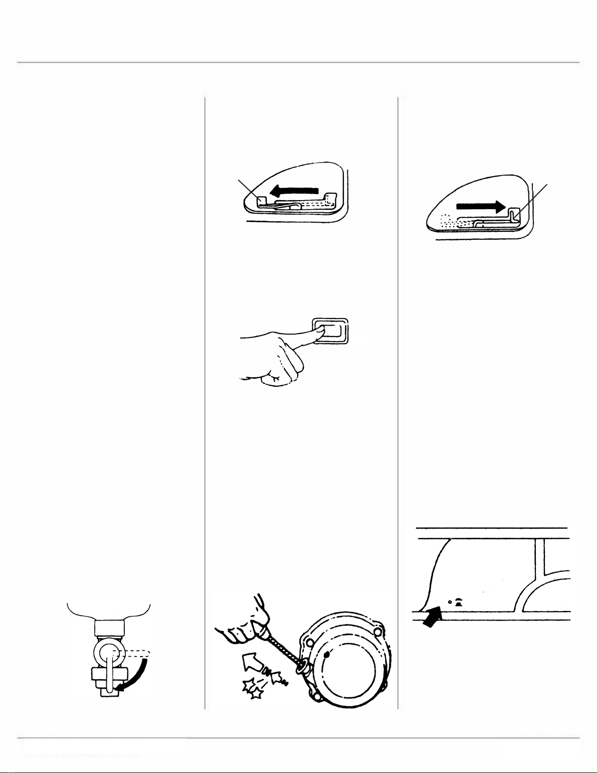
4.Remove the Fuel Tank Cap
and check the fuel level. (See
Figure C.)
FIGURE A Grounding Rod
1 GALLON
UNLEADED
GASOLINE
2.5 FLUID OUNCES
2-CYCLE OIL
APPROVED
CONTAINER
FIGURE B
FUEL
TANK
CAP
STRAINER
FIGURE C
3
4.Turn the Engine Choke Lever
to its "CHOKE" position. Set the
Choke Lever in the "RUN"
position when starting a warm
Engine. (See Figure E.)
5.Then turn the Engine Power
Switch to its "ON" position. (See
Figure F.)
6.Grasp the Recoil Starter
Handle and pull slowly until
resistance is felt. While holding
the Handle, allow the Starter
Rope to rewind slowly. Then, pull
the Starter Handle with a rapid,
full arm stroke. Once again while
holding the Handle, allow the
Rope to rewind slowly. Repeat as
necessary, until the Engine
starts. (See Figure G.) warm up
for five minutes after starting with
no electrical load.
5. After the Engine starts and
warms up, slowly move the
Choke Lever to its "RUN"
position. (See Figure H.)
IMPORTANT: Allow the Engine
to run at
6. no load until warm (approx. 3
minutes) after each start-up to
allow the Engine to stabilize.
EQUIPMENT OPERATION
1.The total combined load
through the outlet on the
Generator must not exceed the
rated maximum power of the
unit.
2.Always reduce the load if the
AC Circuit Breaker turns off.
Once the load is reduced, press
the Breaker to reset the
Generator and continue
operation. (See Figure I.)
3.Allow the Engine to run at no
load until warm (approx. 3
minutes) after each start-up to
allow the Engine to stabilize.
4.To fill the Fuel Tank, first wipe
off the Fuel Tank Cap and the
surrounding area. (See Figure
C.)
5.Unscrew, and remove the Fuel
Tank Cap (See Figure C.)
6.Remove the Strainer and
remove any dirt and debris.
Then replace the Strainer. (See
Figure C.)
7.Fill the Fuel Tank to about 1
inch under the fill neck of the
Tank with the pre-mixed
unleaded gasoline/2-cycle oil
mixture.
8.Then replace the Fuel Tank
Cap (See Figure C.)
TO START THE ENGINE
1.Check to make sure the
Engine Switch is in its "OFF"
position.
2.IMPORTANT:Make sure to
unplug any load from the
Generator before starting to any
appliance, tool, or equipment.
3.Turn the Engine Fuel Switch to
its "ON" position. (See Figure D.)
"ON"
FIGURE D
Choke
Lever
"CHOKE"
"RUN"
FIGURE E
ON
FIGURE F
FIGURE G
Choke
Lever
"CHOKE"
"RUN"
FIGURE H
RESET
OFF
FIGURE I
CIRCUIT
BREAKER
4
DC cord has been supplied with
the unit.
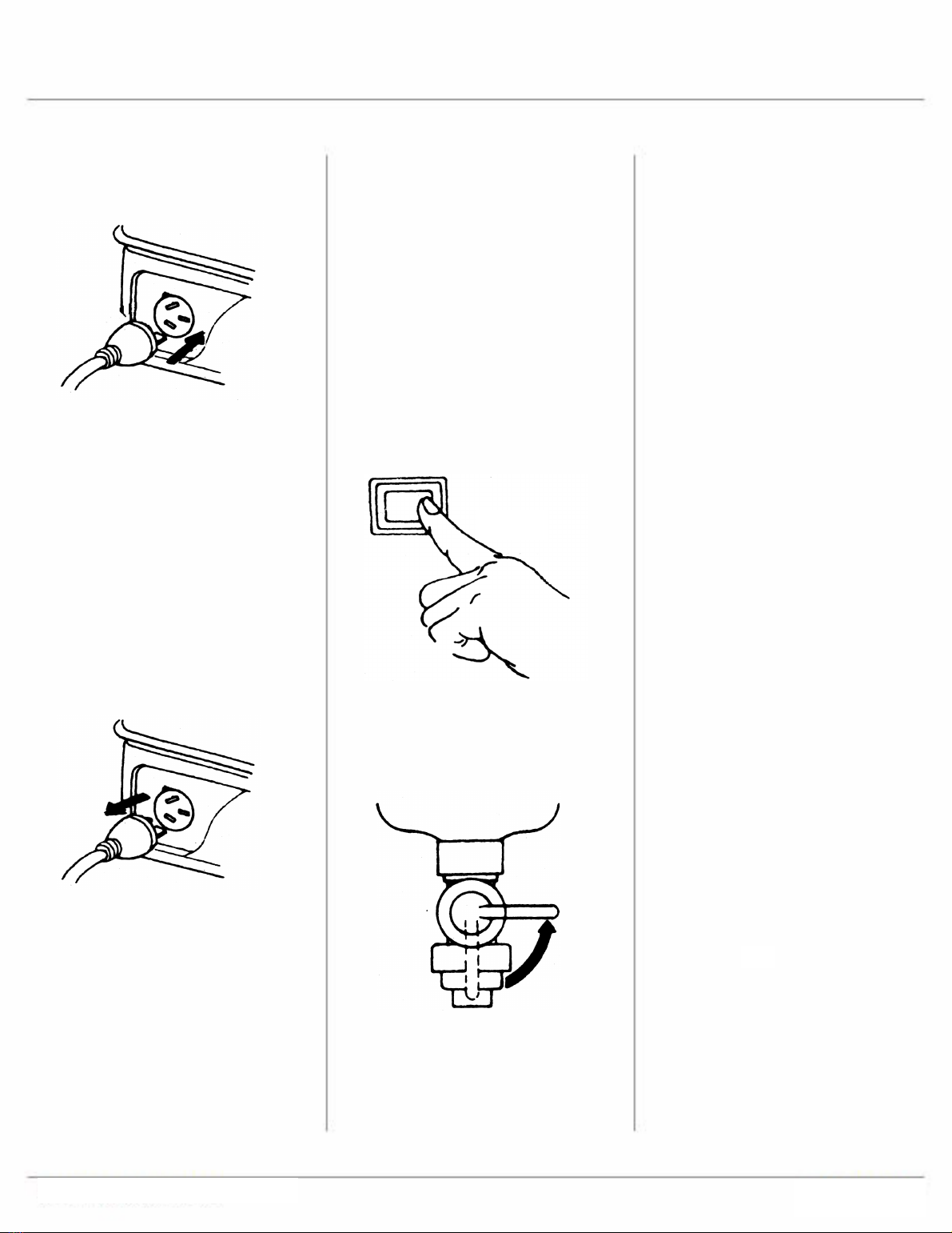
GENERATOR SHUT OFF
1.Remove all electrical load
devices from the Generator. (See
Figure K.)
2.Allow the Engine to run for
approximately 3 minutes with no
electrical load.3.Turn off the
Generator’s Power Switch to stop
the Engine.(See Figure L.)
4.Turn the Fuel Switch to its
"OFF" position. (See Figure M.)
5.Allow the Generator to
completely cool before
storing.with no electrical load.
MAINTENANCE
Many maintenance
procedures, including those
not detailed in this manual, will
need to be performed by a
qualified technician for safety.
If you have any doubts allow
the Engine to stabilize.about
your ability to safely service
the equipment or Engine, have
a qualified technician service
the equipment instead.
Air Filter Element Maintenance:
1.Wipe off the Air Cleaner Cover.
Then remove the Cover. (See
Figure N.)
2.Remove the Air Filter Element.
3.Wash the Air Filter Element in
warm water and mild detergent
several times. Rinse. Squeeze
out excess water and allow it to
dry completely. Soak the Filter in
lightweight oil briefly, then
squeeze out the excess oil.
4.Install the new Air Filter
Element or the cleaned Filter.
Secure the Air Cleaner Cover
before use.
4.Plug the power cord of the 120
volt appliance/tool into the 120
volt AC Outlet on the Generator.
(See Figure J.)
5.NOTE: Do not allow the
generator to completely run out
of fuel with devices attached. A
generator’s output may sharply
spike as it runs out of fuel,
causing damage to attached
devices.
6.When finished using the
appliance/tool, unplug its power
cord from the AC Outlet on the
Generator. (See Figure K.)
7.For DC current, plug into the
DC plug located on the side of
the generator. To charge your
car battery, connect the alligator
clips to the corresponding
terminals on your battery, The
red lead goes to the positive (+)
terminal and the black lead goes
to the negative (-) terminal. This
FIGURE J
FIGURE K
OFF
FIGURE L
FIGURE M
OFF

5
Spark Plug Maintenance:
1.Disconnect Spark Plug Wire
from end of plug. Clean out
debris from around Spark Plug.
2.Using the spark plug wrench
provided, remove the Spark
Plug.
3.Inspect the Spark Plug:If the
electrode is oily, clean it using a
clean, dry rag. If the electrode
has deposits on it, polish it using
emery paper. If the white
insulator is cracked or chipped,
the Spark Plug needs to be
replaced.
4.When installing a new Spark
Plug, adjust the Plug’s gap to the
specification on the Technical
specification chart and in the
FIGURE N
FIGURE O
illustration below. Do not pry
against the electrode or the
insulator, the Spark Plug can be
damaged. (See Figure O.)
5.Install the new Spark Plug or
the cleaned Spark Plug into the
Engine. Gasket-style: Finger-
tighten until the gasket contacts
the cylinder head, then about
1/2-2/3 turn more.
Non-gasket-style: Finger-tighten
until the plug contacts the head,
then about 1/16 turn more.
Cleaning, Maintenance, and
Lubrication Schedule: Engine
Note: This maintenance
schedule is intended solely as a
general guide. If performance
decreases or if the Engine
operates unusually, check
systems immediately. The
maintenance needs of this
Engine will differ depending on
factors such as temperature, air
quality, fuel quality, and other
factors.
Note: These procedures are in
addition to the regular checks
and maintenance explained as
part of the regular operation of
the Engine.
After Initial 25 Operation Hours:
1.Change unleaded gasoline
and 2-cycle oil fuel mixture.
Every 25 Operation Hours
Thereafter:
1.Clean/replace Air Filter
Element.
2.Inspect/clean Spark Plug.
Every 50 Operation Hours:
1.Change unleaded gasoline
and 2-cycle oil fuel mixture.
Every 100 Operation Hours:
1.Replace Spark Plug.
Replace Air Filter Element.
Note: All maintenance
procedures scheduled for 20, 50,
and 100 operation hours should
be performed at least yearly.
Every 300 Operation Hours:
1.Clean Fuel Tank and
Carburetor assembly.
2.Clean carbon build-up from
Combustion.
Maintenance and Cleaning
Schedule: Generator
Before Every Use:
1.Check to make sure all bolts
and nuts are tight.
2.Check for any damage to the
Generator.If damaged, do not
use until repaired by a qualified
service technician.
After Every Use:
1.Allow the unit to completely
cool. Then clean the exterior of
the Generator with a clean cloth.

6
Recommended Maintenance Schedule
each use
first month of
use or first 20
hrs
every 3
months or
50 hrs
every 6
months or
100 hrs
every year
or 300 hrs
As
necessary
Engine oil check level x
Air cleaner check x
Clean x
fuel filter cup Clean x
spark plug check/ clean x
gas tank check gas level x
Clean x
Run generator premix gas out prior to long periods of storage

7
Troubleshooting Guide-Engine
Problem Possible Causes Probable Solutions
Engine will not
start
FUEL RELATED:
Improper gasoline/2 cycle oil mix.1.
No fuel in tank or fuel valve closed.2.
Choke not in start position, especially3.
with cold engine.
Low quality or deteriorated, old4.
gasoline.
Carburetor not primed.5.
Dirty fuel passageways blocking fuel6.
flo .
Carburetor needle stuck. Fuel can be7.
smelled in the air.
Too much fuel in chamber. This can be8.
caused by a stuck carburetor needle.
FUEL RELATED:
Mix 50 parts unleaded gasoline with 11.
part 2-cycle oil.
Fill fuel tank and open fuel valve.2.
Move choke to start position if engine3.
is cold.
Use only fresh 89+ octane unleaded4.
gasoline and 2-cycle oil mixture.
Prime carburetor by pressing priming5.
bulb specified number of times (if
equipped).
Clean out passageways using fuel6.
additive. Heavy deposits may require
further cleaning.
Gently tap side of carburetor float7.
chamber with screwdriver handle.
Turn choke to run position. Remove8.
spark plug and pull the start handle
several times to air out the chamber.
Reinstall spark plug and set choke to
start position.
IGNITION (SPARK) RELATED:
Spark plug wire not connected1.
securely.
Spark plug electrode wet or dirty.2.
Incorrect spark plug gap.3.
Spark plug wire or spark plug broken.4.
Incorrect spark timing or faulty ignition5.
system.
IGNITION (SPARK) RELATED:
Connect spark plug wire properly.1.
Clean spark plug.2.
Correct spark plug gap.3.
Replace spark plug wire and/or spark4.
plug.
Have qualified technician diagnose5.
repair ignition system.
COMPRESSION RELATED:
Cylinder not lubricated. Problem after1.
long storage periods.
Loose or broken spark plug. (Hissing2.
noise will occur when trying to start.)
Loose cylinder head or damaged head3.
gasket. (Hissing noise will occur when
trying to start.)
Engine valves or tappets misadjusted4.
or stuck.
COMPRESSION RELATED:
Pour tablespoon of oil into spark plug1.
hole. Crank engine a few times and try
to start again.
Tighten spark plug. If that does not2.
work, replace spark plug. If problem
persists, may have head gasket
problem, see #3 below.
Tighten head. If that does not remedy3.
problem, replace head gasket.
Adjust valve clearance. If that does not4.
work, clean or replace valves/tappets.

8
Troubleshooting Guide-Engine
Problem Possible Causes Probable Solutions
Engine misfire Spark plug wire loose.1.
Incorrect spark plug gap or damaged2.
spark plug.
Defective spark plug wire.3.
Old or low quality gasoline.4.
Incorrect compression.5.
Check wire connections.1.
Re-gap or replace spark plug.2.
Replace spark plug wire.3.
Use only fresh 89+ octane unleaded4.
gasoline and 2-cycle oil mixture.
Diagnose and repair compression. (Use5.
Engine will not start: C
RELATED section.)
Engine stops
suddenly
Fuel tank empty or full of impure or low1.
quality gasoline.
Defective fuel tank cap creating2.
vacuum, preventing proper fuel flo .
Improper idle speed.3.
Faulty magneto, incorrect timing, or4.
clogged carburetor.
Fill fuel tank with fresh 89+ octane1.
unleaded gasoline and 2-cycle oil
mixture.
Test/replace fuel tank cap.2.
Properly adjust idle speed.3.
Have qualified technician diagnose and4.
service engine.
Engine knocks Old or low quality gasoline.1.
Engine overloaded.2.
Incorrect spark timing, deposit buildup,3.
worn engine, or other mechanical
problems.
Fill fuel tank with fresh 89+ octane1.
unleaded gasoline and 2-cycle oil
mixture.
Do not exceed equipments load rating.2.
Have qualified technician diagnose and3.
service engine.
Engine backfire Impure or low quality gasoline.1.
Engine too cold.1.
Choke not open after engine warm.2.
Engine not properly adjusted for high3.
altitude operation.
Intake valve stuck, choke stuck,4.
incorrect timing, clogged carburetor, or
overheated engine.
Fill fuel tank with fresh 89+ octane1.
unleaded gasoline and 2-cycle oil
mixture.
Use cold weather fuel and oil additives2.
to prevent backfiring
Move choke to run position after engine3.
warms up.
Qualified technician must adjust engine4.
at altitudes greater than 5,000 feet
above sea level.
Have qualified technician diagnose and5.
service engine.


10
Limited Manufacturer Warranty
North American Tool (NAT) Industries makes every effort to ensure that this product meets high quality
and durability standards. NAT warrants to the original retail consumer a 1-year limited warranty from
the date the product was purchased at retail and each product is free from defects in materials.
Warranty does not apply to defects due directly or indirectly to misuse, abuse, negligence or accidents,
repairs or alterations, or a lack of maintenance. NAT shall in no event be liable for death, injuries to
persons or property, or for incidental, special or consequential damages arising from the use of our
products. To receive service under warranty, the original manufacturer part must be returned for
examination by an authorized service center. Shipping and handling charges may apply. If a defect is
found, NAT will either repair or replace the product at its discretion.
DO NOT RETURN TO STORE
For Customer Service:
8807517 12/12
1250 XLT GENERATOR
Model: 51769
m
For customer service, call 1-800-348-5004 or email
11
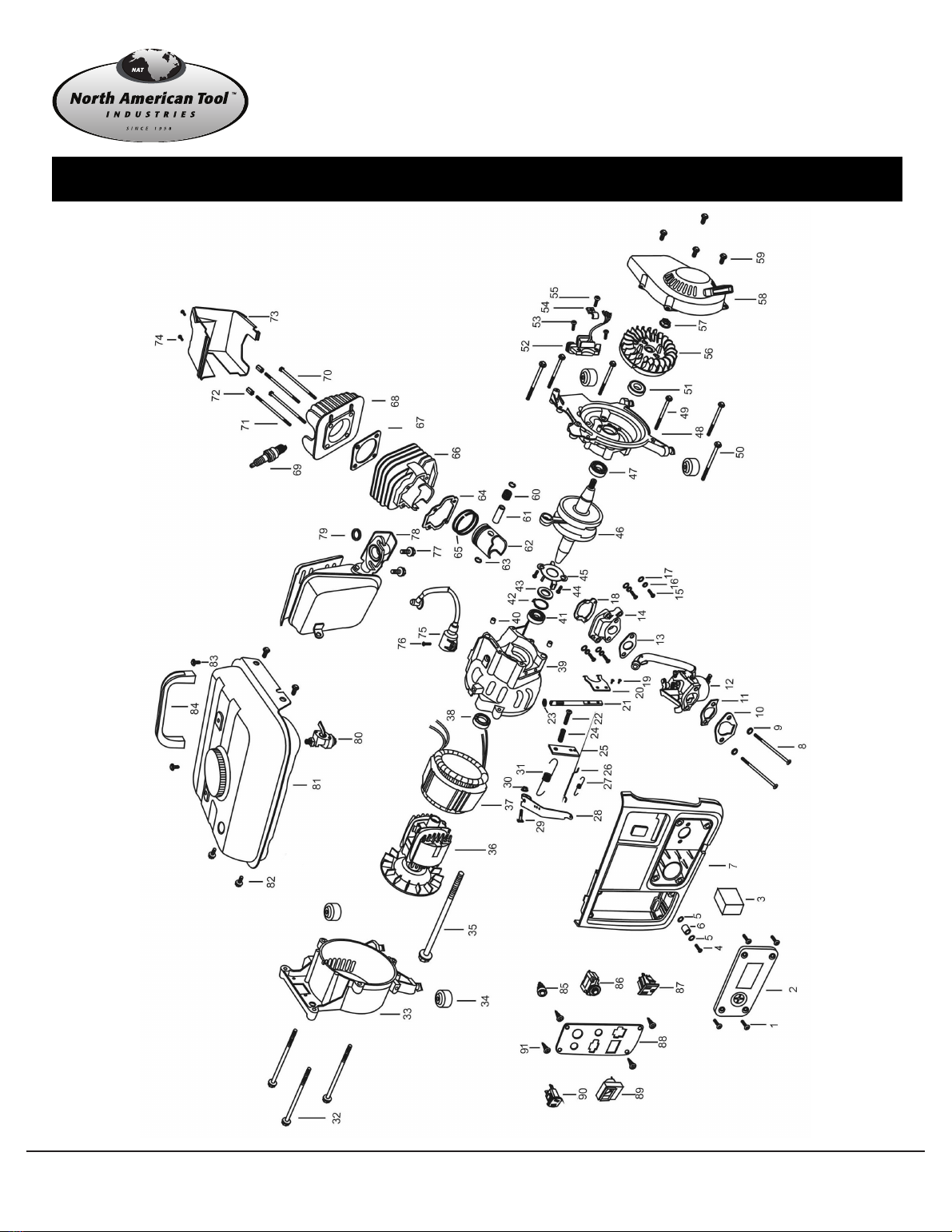
Parts List

8807517 12/12
m
12
Call 1-800-348-5004 for assistance or replacement parts
Please provide the following information
-Model number
-Part description and number as shown in parts list
-Serial number
Address any correspondence to:
North American Tool Industries
84 Commercial Rd
Huntington, IN 46750
Parts List
Part No. Description Q’ty Part No. Description Q’ty
1 Bolt 5x 16 4 47 bearing 6004 1
2 Air cleaner cover 1 48 Left crankcase 1
3 Air filter element 1 49 Flange bolt 6x50 4
4 Bolt rivet 6 x 40 1 50 Flange bolt 6x55 2
5 Flat washer 2 51 Big oil sealing 1
6 Steel set 1 52 Magnetic motor 1
7 Control panel 1 53 Bolt 6x16 2
8 Bolt 6x65 2 54 Press board 1
9 Spring washer 4 55 Flange bolt 1
10 Filter flange 1 56 Flywheel 1
11 Carburetor cushion I 1 57 Flange bolt 10x1.25 1
12 Carburetor assembly 1 58 start cover 1
13 Carburetor cushion II 1 59 Flange bolt 6x12 4
14 Valve 1 60 Needle bearing 1
15 Bolt 6x20 4 61 piston pin 1
16 Spring washer 4 62 Piston 1
17 Flat washer 4 63 Piston pin fender ring 2
18 Seal ring 1 64 Cylinder seal cushion 1
19 Bolt 3x8 2 65 Piston ring 1
20 Adjustable speed fork 1 66 Cylinder block 1
21 Adjustable speed lever 1 67 Cylinder head gasket 1
22 Bolt 6x40 1 68 Cylinder head 1
23 Seal ring 1 69 Sparkle plug 1
24 Press spring 1 70 Flange bolt 6x100 2
25 Adjustable speed piece 1 71 Double head bolt 6x113 2
26 Adjustable speed pull lever 1 72 Long shape nut 6x20 2
27 Adjustable spring 1 73 Cylinder head cover 1
28 Adjustable speed arm 1 74 Flange bolt 6x12 2
29 Square bolt 1 75 High tension line 1
30 Nut 1 76 Bolt 6x20 1
31 Pull Spring 1 77 Flange bolt 6x16 2
32 Flange bolt 6x80 3 78 Muffler 1
33 Back cover 1 79 Washer 1
34 Shock absorber foot 4 80 Fuel switch 1
35 Flange bolt 8x154 1 81 Fuel tank 1
36 Rotor 1 82 Flange bolt 6x12 4
37 Stator 1 83 Round head bolt 6x35 2
38 Big oil sealing 1 84 Handle 1
39 Right crankcase 1 85 Pilot lamp 1
40 Fixing pin sheath 2 86 Circuit breaker 1
41 Bearing 6004 1 87 AC receptacle 1
42 Fender ring 47 1 88 Iron faceplate 1
43 Slide block 1 89 Voltmeter 1
44 Bolt 6x12 2 90 DC plug 1
45 shelf 1 91 Bolt 4
46 Bent axle 1

This manual suits for next models
1
Table of contents
Other North American Tool Portable Generator manuals

Popular Portable Generator manuals by other brands

North Star
North Star M165912I.4 owner's manual

Champion
Champion PRO 100430 Operator's manual

Generac Power Systems
Generac Power Systems MAGNUM MGG200 manual

Craftsman
Craftsman 580.327160 owner's manual

Mase
Mase FM 8000 S Use and maintenance manual

Rohde & Schwarz
Rohde & Schwarz R&S SMU200A Service manual


