North Creek Big Kat North D28 User manual

! " # $ % & # ' ( ( ( ( $
)( * + , !

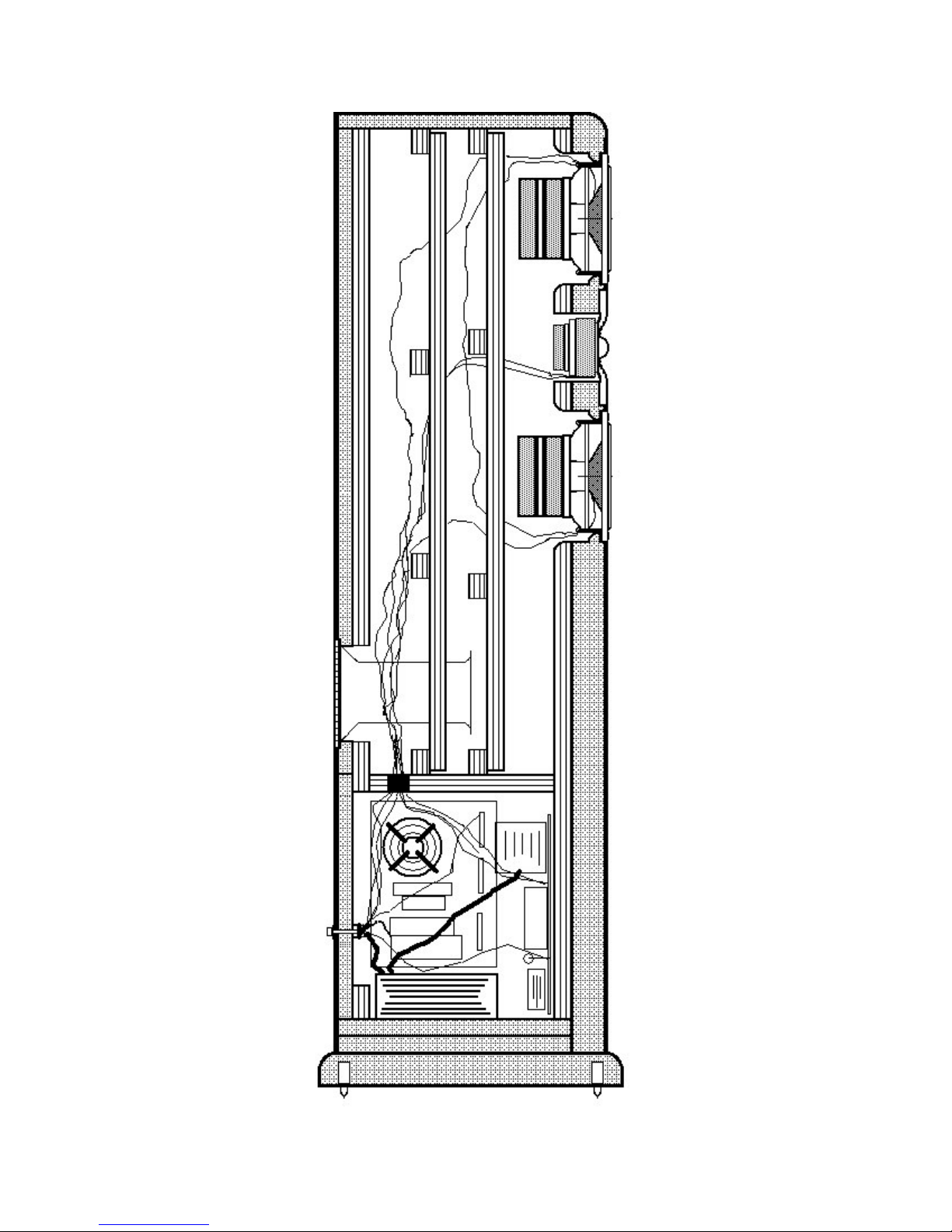
The woodworker's kit portion of this loudspeaker system was shipped in two cartons.
Carton #1 contains:
(1) Instruction Package.
Cabinet Manual
Response Curves
The North Creek Cabinet Handbook
The North Creek Wiring Guide
(2) 3" x 5" Flared Port Tubes assemblies.
(150) Drinking Straws
(1) Bottle of Aleene's Super Tacky Glue
(2) Roll of 1/16" gasket tape.
(28) #6-1" pan head black screws.
(20) #6-1 5/8" flat head black screws.
(8) #10-2" flat head deck screws.
(2) Sets of Big as Texas Binding Posts.
(1) Set of Big Toe Spikes.
(1) Set of Very Big Toe Spikes.
(2) Woofer Crossovers.
(2) Tweeter Crossovers
Carton #2 contains:
(2) shielded North D28-06S Tweeters.
(4) shielded Scan-Speak 15W/4530K-00SC Woofers.
(2) 6 oz. Rolls of Dacron stuffing.
You will need to purchase a tube of silicone sealant. These items should be available at
your local garden shop.


This publication is copyright August 1, 2008 by North Creek Music Systems. The
cabinet design is the intellectual property of North Creek Music Systems.
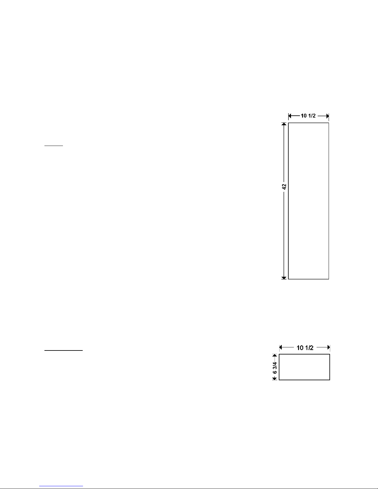
Sides
4 Pieces
3/4" MDF (may be pre-veneered)
10 1/2 x 42
Top/Bottom
3/4" MDF
10 1/2 x 6 3/4
6 Pieces

Inner Front, Inner Back
3/4" Plywood
6 3/4 x 39 3/4
4 pieces

Horizontal Shelf Brace
3/4" plywood
6 3/4 x 8 1/4
2 Pieces
Ladder Braces
3/4" plywood
1 1/4 x 28 1/2 4 pieces
1 1/4 x 6 1/2 16 Pieces

Lower Back Cover
3/4" MDF
6 3/4 x 11
2 Pieces
Outside Upper Back
3/4" MDF
6 3/4 x 28 3/4
2 Pieces
Port Cut Out::
Countersink
To be deterimined

Fascia
1½" MDF (may be double 3/4", laminated)
If laminating, use a hard glue such as Titebond.
or Solid Hardwood
8 1/4 x 42
2 pieces (4 if using 3/4" MDF)

Plinth and Plinth Detail
3/4" MDF
12 x 13 3/4
4 Pieces (laminated)
Spike holes are on the outside corners, 1/2" diameter, 1" deep. Spike inserts are
installed with a 10 mm hex drive.
Four holes to attach to the bottom of the cabinet take #10 - 2" deck screws.

Fascia Detail
Fascia: Material is 1 1/2" MDF, cut 8 1/4 x 42
and rounded over 1" on the front side edges.
It is much easier to lay out the driver and screw
hole positions before this piece is machined. The
woofer screw holes need to be drilled at a slight
angle for the screws to bite fully.
Cut Outs:
See the detailed drawing below for
flare information
Scan-Speak 15W-4530K00SC:
Countersink diameter 5 15/16",
depth 7/32", through 5"
North D28-06S:
Countersink diameter 4 1/8",
depth = 5/32", through 3 1/8"
Note ears.

Inner Front Detail
Cut Outs:
Scan-Speak 15W-4530SC: through
diameter 5 3/4" , flared on the inside
edge of the cabinet. The flare bit
should be a quarter round of 3/8"
radius. See below for a detailed
drawing.
D28 through diameter 3 1/2".

Driver Cut Out Close-Up Top View
Note that we suggest a "double flare" -
the first immediately behind the front edge of the driver,
the second as the inner front meets the cabinet.
The magnet is quite large and the double flare is required to allow the cone to breath.

Inner Back Detail
The cut outs are large enough to allow
mounting of the crossover boards.

Lower Back Cover Detail
The holes along the edge are
sized to accept #6 x 1 5/8" drywall screws.
The center holes are 9/32" to accept North Creek Texas Posts.
Drill two holes for single wiring or four holes for bi-wiring.

Shelf Brace Detail
The through hole is 3/4" diameter

Cabinet Assembly
1) Pre-assemble all parts without glue, to view the cabinet inside, bracing structure, and
test the fit.
2) Mark "FRONT" and "TOP" directions (and use arrows) on the inside of all panels.
Use a large black marker.
3) Mark the ladder brace edge and corner distances from the front of the cabinet sides
on the inside of all side panels. Make sure to leave enough room at the top edge for the
top panel, and do not go too low or the ladder braces will be in the way of the shelf
brace.
4) Begin the gluing process by laying up the inner back and outer back with North Creek
Soft Glue. A few well placed 1" brads will assure the panels will not flow. Also, attach
the ladder braces to the side panels with hard glue. They will try to move, so it is
easiest to hold them in place by tacking them with a 1 3/4" or 2" brad.
5) Begin the main gluing process, starting with side/top/back. Break several hours
between steps to allow the glue to dry. (Or use the "two drill method" outlined in the
North Creek Cabinet Handbook.)
6) Gluing order is side/top/back, inner front, horizontal shelf brace bottom, side. It is
easiest to install the cross braces with pinch clamps.See the drawing next page for the
brace positions.
6) Test-fit the Lower Back Cover. It may need to be trimmed a touch to be a perfect fit.
7) Drill the pilot holes through the Lower Back Cover into the Inner Back. The pilot
holes should be 1/8" for #6 - 1 5/8 drywall screws.
Advice
When pre-assembling, take your time to make sure the panels fit together perfectly.
This usually means rotating and revolving panels until a set is reached that works just
right. Label each panel carefully on the inside with a large black marker to assure the
sets do not get mixed up during assembly.
Use a lot of glue. It's much easier to get the glue between the panels before they are
glued together.
Remember, when clamped, panels tend to "flow" to relieve the pressure. An
inexpensive air brad nailer and a variety of nails is invaluable in stabilizing the panels
while they dry.
Pinch clamps for the cross braces are invaluable. To get pressure on the top or shelf
brace, use scrap wood though the woofer holes with a long clamp to make a wedge.

Brace Positions
This detail is a side-view of the center of the cabinet.
The measurement is taken from the front edge of the cabinet, before the fascia is
attached.

Fascia Installation
The main cabinet and fascia should be finished separately.
The fascia should be filled, primed, and painted prior to attachment to the main cabinet.
1) Coat the rear of the fascia with a thin layer of Aleene's Super Tacky, and lay it face
down on top of a heavy plastic bag, on a smooth flat surface just slightly larger than the
fascia.
2) Position the cabinet and clamp the cabinet to the surface below the fascia.
3) One may add a few 1 5/8" drywall screws though the inner front and into the fascia
via the crossover chamber.

Plinth Installation
The plinth should be finished separately. The best results are by rounding, filling, and
sanding smooth the top edged, then painting black.
1) Lay the cabinet on its back, resting on several slats of 3/4" material.
2) Position the plinth and drill pilot holes through the bottom of the plinth and into the
bottom of the cabinet.
3) Remove the plinth and enlarge the pilot holes if necessary.
4) Attach the plinth to the cabinet with #10 by 2 1/2" deck screws.
Woofer Crossover Installation
1) With the cabinet on its front, liberally coat the inside of the front with silicone or
mastic adhesive. You may also use hot melt but you will need to be quick. Place the
woofer crossover board on the inside of the front of the cabinet such that the small red
inductor is at the bottom. Let it dry several hours or overnight.
2) Feed the long red and black wires terminated with 1/4" quick connects through the
upper 3/4" hole of the Shelf Brace and into the driver chamber
Make sure the black ring-connector termination is still free in the bottom of the cabinet.
Tweeter Crossover Installation
1) With the cabinet on its right side (as you face the font of the speaker), liberally coat
the inside of the right side with silicone or mastic adhesive. Again, hot melt will work but
be quick. Place the tweeter crossover onto the adhesive, with the large inductor as
close to the shelf brace as possible. Let it dry several hours or overnight.
2) Feed the white and blue wires terminated with 110” gold quick connects through the
lower 3/4" hole of the Vertical Divider and into the driver chamber
3) Seal the wiring and shelf brace with a liberal supply of silicone. Make sure there are
no leaks - it is very important that this seal is air tight.

Connecting to the Binding Posts
Binding posts fit in the horizontal holes of the rear cover, as follows: on the outside
goes the hex-head, ring and stop. On the inside goes the gold-plated star washer and
one nut. Tighten to prevent spinning. Next comes the gold-plated crossover connector
(described below), followed by a second gold plated nut.
1) Attach the Big as Texas Postbinding posts to the rear covers in the order of Red-
Black-Black-Red.
2) Attach the loudspeaker internal wiring to the binding posts as follow:
White (tweeter +) to Red Post #1.
Blue insulated (tweeter -) to Black Post #1.
Black insulated (woofer -) to Black Post #2.
Coil lead (woofer +) and long red lead to Red Post #2.
3) Make sure the nuts are good and tight, the dab nail polish on the thread of the
binding posts to prevent the nuts from coming loose.
Woofer Inductor Installation
With the cabinet standing up on its Plinth, liberally coat the bottom and corners of the
large woofer inductor with silicone or mastic. Set the inductor on the bottom of the
cabinet such that the bottom and two coated corners are touching the back left corner of
the cabinet (as viewed from the front). Add more adhesive. Let dry overnight.
Back Cover Installation
Spray paint the heads of the 1 5/8 screws jet black. Fusion Satin Black works best.
Adhere gasket tape to the inner back and attach the back cover.
Other North Creek Speakers manuals