North Shore Safety LineGard PGFS-13105 User manual

INSTALLATION AND TESTING
PROCEDURE
Line
LineLine
Line
Gard
Gard Gard
Gard
Grou
IMPORTANT!
THIS DEVICE MUST BE IN
STALLED BY A
QUALIFIED PERSON WHO UNDERSTANDS
ELECTRICAL CIRCUITS.
Please read all the information on this sheet.
WARNING
Ground Fault Circuit Interrupter (GFCI)
is a safety
device under normal use and it is not intended to
promote activity of elevated
risk. Use only within the
specified operating parameters (
Failure to do so may
result in bodily injury)
. Consult a licensed electrician
for assistance on installation and repairs. Do not use
this GFCI if it fails to function as instructed. Never
attempt
to tamper with this device. This GFCI should
never be used as a switch to connect or disconnect
power. (
Power should be disconnected at main
power feed or by secondary switch located at the
primary feed of GFCI). This GFCI is not an over-
current protection device. (
An appropriate current
breaker should be used in series at primary power
feed).
This GFCI does not provide protection against
shocks caused by holding both circuit conductors.
This GFCI does not provide protection against
electrical shocks gen
erated by the conductors
supplying power to the device. Note:
primary feed to
GFCI is live even when GFCI is tripped. (Power
should be disconnected at main service panel
before servicing load side of GFCI.)
•
Do not use this device to feed power to life
support apparatus.
•To minimize nuisance tripping:
o
Do not use on swimming pool
equipment installed before 1965 NEC
code.
oLimit load cable to 250 feet.
o
Do not use on electric clothes dryers
or electric ranges with frames
grounded by Neutral conductor.
•Installa
tion must comply with local and
national electrical codes (NEC).
•
Turn power off at the service panel to prevent
serious injuries.
North Shore Safety, Ltd.
North Shore Safety, Ltd.North Shore Safety, Ltd.
North Shore Safety, Ltd.
Safety Through Innovation
N
What is a GFCI?
A GFCI is a device designed to interrupt
power when a ground fault (a current that takes a path
to ground) e
xceeds a predetermined value. The
interruption of this power is fast in order to prevent
serious injuries.
Why do we need a GFCI?
The human body is conductive to electricity.
However, we were not meant to do so. Electric shocks
can be fatal. Any electrica
l tool or appliance is a
potential shock hazard especially when used near wet
locations. That’s where a GFCI is needed the most
and can save your life. This is why most electrical
codes require GFCI protection in kitchens, bathrooms,
garages, outdoor outle
ts, laundry rooms, workshops,
etc..
North Shore Safety’s GFCI LineGard will offer such
protection. Its safety scope surpasses its peers to
include open neutral protection (most receptacle type
GFCIs do not sense open neutral condition), fault
indication, and power status.
How does a GFCI operate?
The GFCI constantly monitors the current
balance of the conductors supplying power to the
load. When a ground fault occurs, by a leakage or by
shock, the imbalance of current is sensed and the
GFCI trips when the
ground fault exceeds 0.006 Amp.
The tripping action must be within a fraction of a
second to prevent serious injuries.
What a GFCI cannot do:
•Will not protect line side.
•
Will not protect you when touching two current
carrying conductors of opposite pola
rity (GFCI
sees this as a load).
•
Will not protect you when touching a line of
another circuit.
•Will not detect overcurrent.
NORTH SHORE SAFETY, LTD.
7335 PRODUCTION DRIVE
MENTOR, OHIO 44060
PHONE: 440-205-9188
TOLL FREE: 877-4 SAFE 4U
FAX: 440-205-9187
WEB SITE: WWW.NSSTLD.COM
EMAIL: [email protected]

SPECIFICATIONS
SPECIFICATIONSSPECIFICATIONS
SPECIFICATIONS
TECHNICAL:
Rated Voltage: 120VAC, 240VAC, 120/240VAC
Operating Voltage Range: 85% to 110% of rated
Current: Up to 30 Amps or Device Rating
Frequency: 60 Hz.
Trip Level: 5 +/- 1mA
Phase: Single
Response Time: 25 mS max.
Dielectric Withstand: 1500 VRMS across contact
4000 VRMS between conductors and enclosure
Voltage Surge Withstand:
6000V impulse, 0.5 microsecond rise time, 100KHZ ringing frequency with 40% decay per cycle
Operating Temperature range: -35°C to +66°C
Leakage Current @ 93% Humidity: Zero
Overload Current: 180 Amps, 50% Inductive
RF Noise Susceptibility: Normal Operation with 0.5 VRMS injected on power line with Frequencies up to 450 MHz.
Let go Line Voltage: 60% of Rated
Grounded Neutral Detection: 2 Ohms or less
GENERAL:
Construction: Industrial Grade Design
Type: Class A
Power – Up Type *: Auto or Manual
Endurance: 5000 Operations Minimum
Open Neutral Protection: Trip Upon Loss of Neutral
Grounded Neutral Protection: Trips if Ground and Neutral touch at load side
Power ON Indication: Lighted Green LED
Power OFF Indication: Blinking Red LED, plus Optional Enunciator
Enclosure NEMA 4X
Mounting Type: Panel, Surface, and Portable
Wiring Application: 3 Wire, Single Phase (Hot, Neutral, and Ground**)
4 Wire, Single Phase (Line 1, Line 2, Neutral, Ground**)
Wiring Connections: Permanent Hardwire ( See Type Under Model Configuration Chart)
Switch Interface Double Insulated
Latching Mechanism: Electromagnetic
False trip due to impact: None
Agency Approval U.L. and CSA
IMPORTANT NOTE:
* Manual configuration should be specified when automatic power up would create an unsafe condition after restoration of circuit power.
** Ground connection is done external to device enclosure.
North shore safety warrants to the consumer its Line-Gard Ground Fault Circuit Interrupter (GFCI) to be free from defects in
materials and workmanship under normal use and service for a period of two years from date of purchase. North Shore Safety, at
its option, will repair or replace the defective GFCI without charge within two years period from date of purchase provided that the
defect occurred during normal use. Defective unit must be returned prepaid, with a description of the problem, and a proof of
purchase date to Quality Assurance Dept., North Shore Safety, Ltd. 7335 Production Drive, Mentor, OH 44060. Please include
$10.00 for shipping and handling cost.
North Shore Safety will not be liable, directly or indirectly, for installation or removal of this device, or for any personal injury, or
property damages, or incidental, indirect, or consequential damages of any kind, as a result of a defective device. The exclusive
remedy under this warranty is the repair or replacement of the defective device. In no case shall North Shore Safety’s liability
exceed the purchase price. This warranty is void if this device is not properly installed, tampered with, not used according to label
instructions and ratings, opened, or abused.
NORTH SHORE SAFETY’S TWO-YEAR WARRANTY
DANGER: HAZARD OF ELECTRICAL SHOCK, BURN, OR EXPLOSION. Disconnect power at main panel
before you start the installation, including Enunciator option installation.
Failure to do so will cause severe shock,
personal injury and death.
INSTALLATION PROCEDURE:
3-Wires, 120VAC application:
•Connect Field-Hot wire to GFCI Line-Hot wire (Solid black) using
a wire connector.
•Connect Field-Neutral wire to GFCI Line-Neutral wire (solid White)
using a wire connector.
•Connect GFCI Load-Hot wire (Black W/White stripe) to protected
equipment or receptacle Hot.
•Connect GFCI Load-Neutral wire (White W/Black stripe) to
protected equipment or receptacle Neutral.
3-Wires, 240VAC application:
•Connect Field-Line 1 wire to GFCI Line-Line1 wire (Solid black)
using a wire connector.
•Connect Field-Line2 wire to GFCI Line-Line2 wire (solid Red)
using a wire connector.
•Connect GFCI Load-Line1 wire (Black W/White stripe) to
protected equipment or receptacle Line 1.
•Connect GFCI Load-Line2 wire (Red W/Black stripe) to protected
equipment or receptacle Line 2.
1. Read all the instructions in this leaflet and on the device
label.
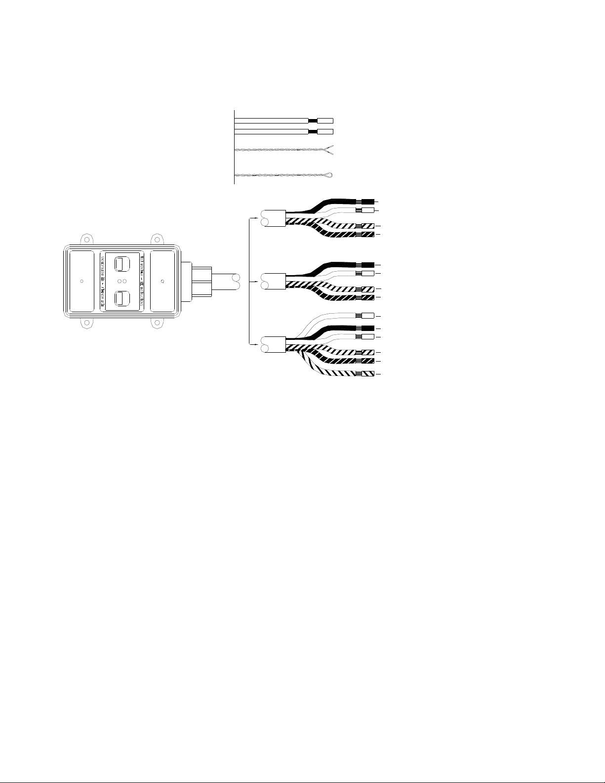
2. Identify all the features and wires (see above drawing)
3. Identify Line wires (solid color) and Load wires (with stripes)
4. Verify that the ratings on the device match your field line
ratings.
5. Disconnect power at main panel.
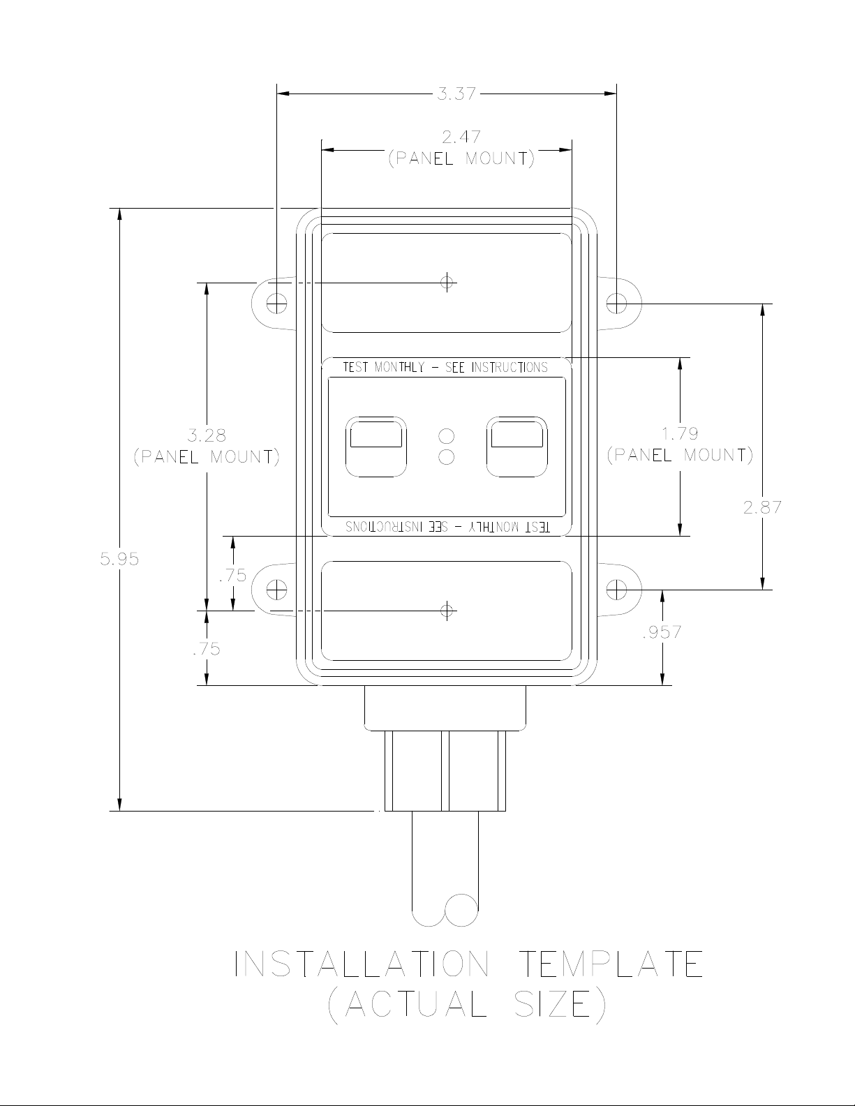
6. Determine GFCI location and drill mounting holes using
pamphlet provided.
7. Strip wires to 5/8”
8. Feed wires into junction box through appropriate hole and
secure cable or conduit end of GFCI to junction box.
9. Choose the right wiring application and connect wires
according to the above drawing.
10. Secure GFCI box to mounting panel.
11. Install covers.
TESTING AND TROUBLESHOOTING
1. Restore the power to the GFCI.
2. Press and release RESET button, Green Light (Power) should turn ON. (For
Auto Power-Up model, Green Light will automatically turn on when power is
restored)
3. Press Test Button. Green Light (Power) turns off and Red Blinking Light (Fault)
turns on.
4. CHECKING FOR CORRECT WIRING:
If GFCI is wired to protect a receptacle, plug a lamp into the protected
receptacle. Press and release the RESET button, lamp should turn on.
Press the TEST button. Lamp should turn off. If lamp stays on when
pressing TEST button, or if lamp does not Light when pressing RESET
button, turn main power off, check and correct your wiring connections.
Repeat steps 1-4. If problem persists, do not use this GFCI. Consult a
qualified electrician.
If GFCI is wired to protect equipment, press and release RESET button.
Verify that equipment power is on. Press TEST button. Equipment power
should turn off. If equipment power does not come on when pressing and
releasing RESET button, or if power stays on when pressing TEST button,
turn main power off, check and correct your wiring connections. Repeat
steps 1-4. If problem persists, do not use this GFCI. Consult a qualified
electrician.
4-Wires, 120/240VAC application:
•Connect Field-Line 1 wire to GFCI Line-Line1 wire (Solid black) using a wire
connector.
•Connect Field-Line2 wire to GFCI Line-Line2 wire (solid Red) using a wire
connector.
•Connect Field-Neutral wire to GFCI Line-Neutral wire (solid White) using a wire
connector.
•Connect GFCI Load-Line1 wire (Black W/White stripe) to protected equipment
or receptacle Line 1.
•Connect GFCI Load-Line2 wire (Red W/Black stripe) to protected equipment or
receptacle Line 2.
•Connect GFCI Load-Neutral wire (White W/Black stripe) to protected
equipment or receptacle Neutral.
120 V
(3-wires)**
(Single Phase)
(Single Phase)
240 V
(3-wires)**
RESET
RESET
W
O
P
E
R
U
F
A
L
T
TEST
TEST
EXTRA WIRES FOR
MODELS WITH
TRIP INDICATOR
OPTIONS
}LINE
LINE 1 (black)
LINE 1 (black w/white stripe)
LINE 2 (red w/black stripe)
LINE 2 (red)
}LOAD
12VDC or 24VDC output for PLC or
other remote DC audible/visual devices.
AC voltage output to remotly power up trip
indicator devices such as beacon light,
alarm, and other visual and audible devices.
Internal enunciator loop. Cut and isolate leads to disconnect
enunciator, connect leads to a toggle switch to turn on or off,
or leave as is if enunciator is desired whenever device trips.
NEUTRAL (white w/black stripe)
NEUTRAL (white)
HOT (black w/white stripe)
}
BLACK
HOT (black)
GRAY (Neutral, L2*)
ORANGE (Hot, L1*)
BLACK (-)
RED (+)
}
}
LOAD
}
LINE
}
** Ground wire is connected externally. Ground wire does not enter or exit the GFCI box. Although GFCI does not require
Ground to operate, Ground connection is recommended and should be made at junction box.
* 240V MODELS
LINE 2 (red)
LINE 2 (red w/black stripe)
LINE 1 (black w/white stripe)
LINE 1 (black) }LINE
LOAD
}
NEUTRAL (white)
NEUTRAL (white w/black stripe)
120/240 V
(Single Phase)
(4-wires)**
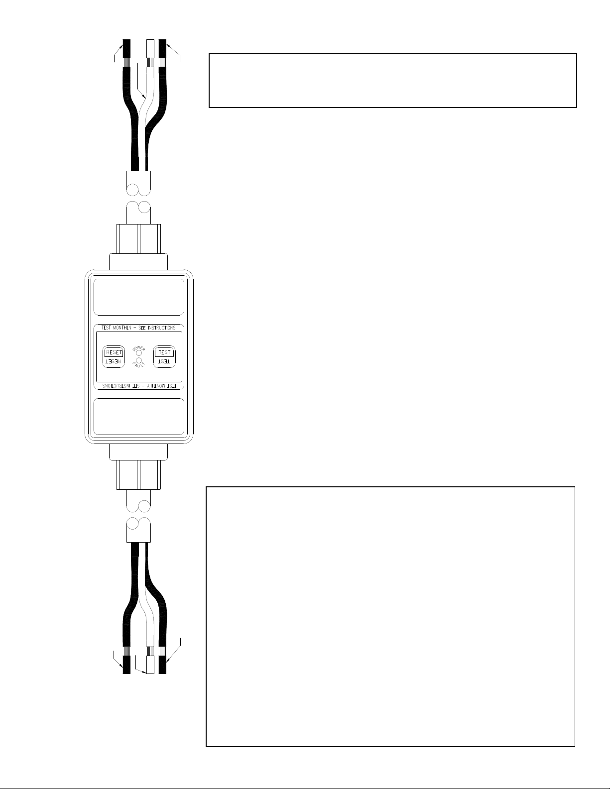
HOT (black)
(LINE 1)*
NEUTRAL (white)
(LINE 2)*
GROUND (green)
HOT (black)
(LINE 1)*
NEUTRAL (white)
(LINE 2)*
GROUND (green)
LOADLINE
DANGER:
HAZARD OF ELECTRICAL SHOCK, BURN OR
EXPLOSION. Disconnect power before you start installation. Failure to
do so will cause severe shock, personal injury or death.
1. Read all the instructions in this leaflet and on the device label.
2. Identify all the features and wires (see drawing)
3. Identify LINE wires and LOAD wires.
4. Verify that the ratings on the device match your field line ratings.
5. Strip wires to 5/8”, or as recommended for your connections.
6. Choose the right wiring application (120V or 240V) and connect wires
according to the drawing on this page and the instructions below.
120VAC Application:
-Connect GFCI Line-Hot wire (Solid Black) to primary Hot.
-Connect GFCI Line-Neutral wire (Solid White) to primary Neutral.
-Connect GFCI Line-Ground wire (Green) to primary Ground.
-Connect GFCI Load-Hot wire (Black) to protected equipment or receptacle
Hot.
-Connect GFCI Load-Neutral wire (White) to protected equipment or
receptacle Neutral.
-Connect GFCI Load-Ground wire (Green) to protected equipment or
receptacle Ground.
TESTING AND TROUBLESHOOTING
1. Apply rated power to GFCI.
2. Press and release RESET button, Green Light (Power) should turn ON.
(For Auto Power-Up model, Green Light will automatically turn on when power
is restored)
3. Press Test Button. Green Light (Power) turns off and Red Blinking Light (Fault)
turns on.
4. CHECKING FOR CORRECT WIRING:
If GFCI is wired to protect a receptacle, plug a lamp into the protected
receptacle. Press and release the RESET button, lamp should turn on.
Press the TEST button. Lamp should turn off. If lamp stays on when
pressing the TEST button, or if lamp does not Light when pressing
RESET button, turn main power off, check and correct your wiring
connections. Repeat steps 1-4. If problem persists, DO NOT USE THIS
GFCI. Consult a qualified electrician.
If GFCI is wired to protect equipment, press and release RESET button.
Verify that the equipment power is on. Press TEST button. Equipment
power should turn off. If equipment power does not come on when
pressing and releasing RESET button, or if power stays on when
pressing TEST button, turn main power off, check and correct your wiring
connections. Repeat steps 1-4. If problem persist, DO NOT USE THIS
GFCI. Consult a qualified electrician.
240VAC Application:
-Connect GFCI Line-Line 1 wire (Solid Black) to primary Line 1.
-Connect GFCI Line-Line 2 wire (Solid White) to primary Line 2.
-Connect GFCI Line-Ground wire (Green) to primary Ground.
-Connect GFCI Load-Line 1 wire (Black) to protected equipment or
receptacle Line 1.
-Connect GFCI Load-Line 2 wire (White) to protected equipment or
receptacle Line 2.
-Connect GFCI Load-Ground wire (Green) to protected equipment or
receptacle Ground.
TEST
TEST
RESET
RESET
R
T
P
O
F
U
A
L
W
E

Table of contents
Popular Surge Protector manuals by other brands


ICM Controls
ICM Controls ICM518 Installation, operation & application guide

Infinite
Infinite Transtector ALPU PTP INJ installation instructions

Liebert
Liebert MP-C5120 quick start guide

Kathrein
Kathrein KAZ 10 manual

Transtector
Transtector TSJ X6 Series installation instructions

Leviton
Leviton 32120-DY3 installation instructions