North Star HRAM-64 User manual

NorthStar^
North Star Computers, Inc.
14440 C ata lina St., San Leandro, C A 94577 USA
(415) 35 7 -8500 TWX/Telex (910) 366-7001
HRAM
HORIZON Random Access Memory
USER /TECHNICAL MANUAL
HORIZON is a registered trademark of North Star Computers, Inc.
Copyright © 1981, by North Star Computers, Inc.
All Rights Reserved
00406B


CONTENTS
Section Pag£
1 INTRODUCTION
1.1 General Description 1-1
1.2 Warranty Information 1-1
1.3 Specifications 1-3
2 INSTALLING AND REMOVING THE HRAM
2.1 Installation 2-2
2.2 Removal 2-3
3 IMPLEMENTING HRAM OPTIONS
3.1 Example Memory Configurations 3-3
3.1.1 Example 1: Three Banks 3-3
3.1.2 Example 2: Three Banks 3-5
3.1.3 Example 3s Four Banks 3-6
3.2 Bank Switching 3-7
3.2.1 Designating Switched Areas 3-7
3.2.2 Designating I/O Port Control Bit 3-9
3.2.3 Software Instructions 3-10
3.2.4 Bank Status on Reset 3-11
3.3 Memory Address Switches 3-13
3.3.1 Revision B Board 3-13
3.3.2 Revision E Board 3-14
3.3.3 32K Board 3-18
3.4 First Quadrant Option (Revision E Board only) 3-19
3.5 Parity Checking 3-20
HRAM USER/TECHNICAL MANUAL

Section Page
3.5.1 Designating I/O Port Control Bits 3-20
3.5.2 Designating Parity Error Response 3-21
3.5.3 Software Instructions 3-22
3.6 Board and Schematic Revision Levels 3-22
4 TESTING THE HRAM
5 THEORY OF OPERATION
5.1 Overview 5-1
5.2 Address Multiplexer 5-3
5.3 Refresh Logic 5-3
5.4 Port CO Detector 5-4
5.5 Address Latch 5-4
5.6 Address Decoder 5-4
5.7 Jumper Area JP1 5-5
5.8 Bank and Parity Logic 5-5
5.9 Strobe Generator 5-6
5.10 Voltage Regulators 5-9
6 TROUBLESHOOTING
6.1 Check HRAM Seating 6-1
6.2 Change Board Slots 6-2
6.3 Check HRAM Configuration 6-2
6.4 Run Diagnostic Programs 6-2
6.5 Replace HRAM 6-3
6.6 Repair Procedures 6-3
HRAM USER/TECHNICAL MANUAL

APPENDICES
A RAM Chip Location Chart A-l
B Bus Signals Used by HRAM B-l
C HRAM 64K - Parts List C-l
D HRAM 64K - Schematics D-l
E Reader Response Form E-l
HRAM USER/TECHNICAL MANUAL


INTRODUCTION 1
This manual supplies the user of the HORIZON Random
Access Memory (HRAM) board with information he or she
needs to install the board and put it into operation.
This includes information on selecting the various
memory options, testing the board and resolving any
difficulties associated with system integration.
The manual also provides information for service
technicians and engineers who may wish to evaluate the
technical aspects of the board or to undertake its
repair.
1.1 GENERAL DESCRIPTION
The HRAM board is a random access memory board designed
for use in the HORIZON computer system.
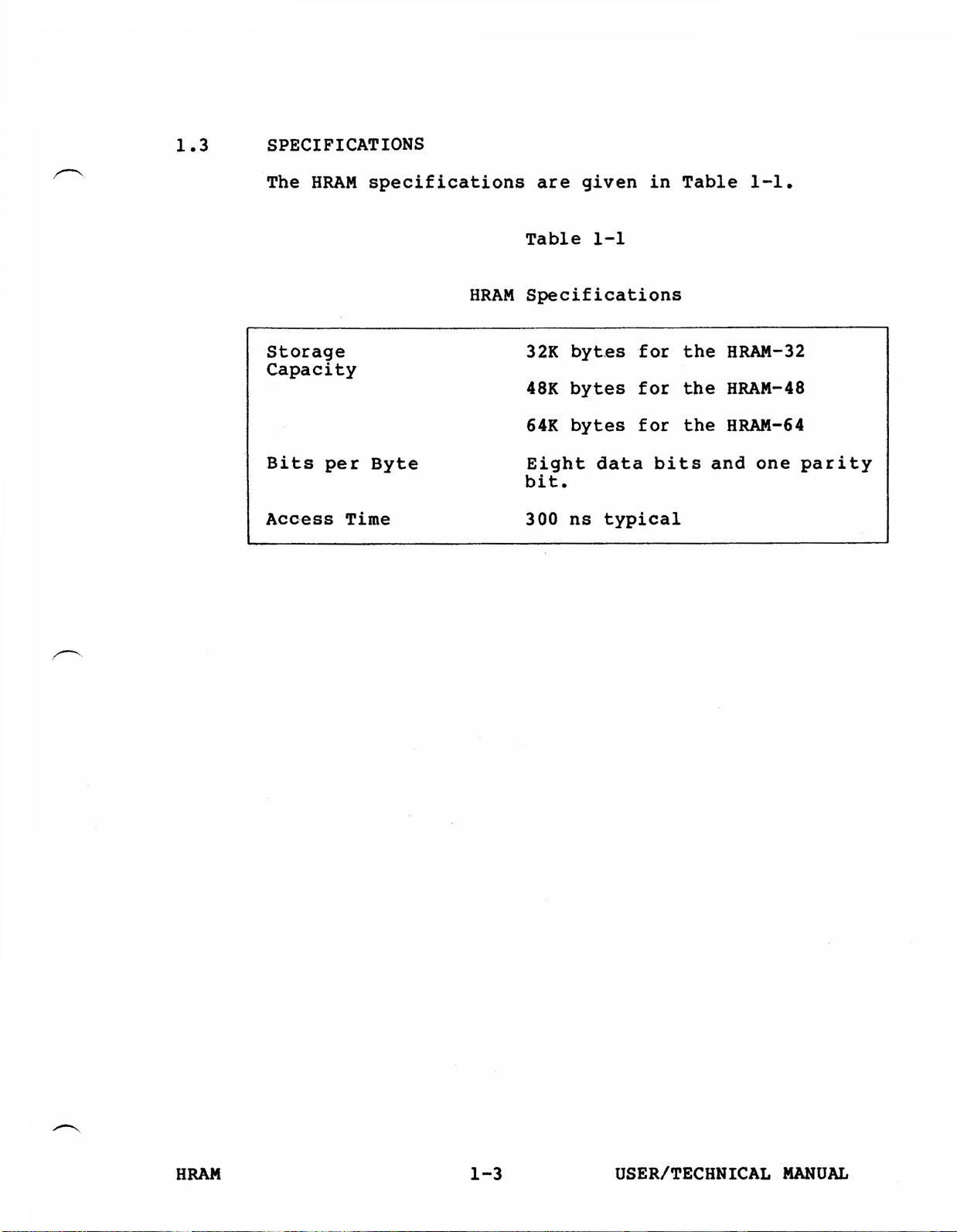
There are three versions of the HRAM board: HRAM-64
with 64K bytes, HRAM-48 with 48K bytes, and HRAM-32
with 32K bytes. The only significant difference
between these boards is the amount of memory they
contain. All three versions incorporate parity error
checking and bank switching capabilities.
1.2 WARRANTY
North Star Computers, Inc., warrants the electrical and
mechanical parts and workmanship of this product to be
free of defects for a period of 90 days from date of
purchase. If such defects occur, North Star Computers,
Inc. will repair the defect at no cost to the
purchaser. This warranty does not extend to defects
resulting from improper use or assembly by purchaser,
nor does it cover transportation to the factory. Also,
the warranty is invalid if all instructions included in
the accompanying documentation are not carefully
followed.
HRAM 1-1 USER/TECHNICAL MANUAL

Should a unit returned for warranty repair be deemed by
North Star Computers, Inc. to be defective due to
purchaser's action, then a repair charge (not to exceed
$50 without purchaser's consent) will be assessed. ANY
UNIT(S) OR PART(S) RETURNED FOR WARRANTY REPAIR MUST BE
ACCOMPANIED BY A DATED COPY OF THE ORIGINAL SALES
RECEIPT. The item should be returned to the dealer
from whom the product was purchased, for implementation
of the warranty. When sending the item to the factory
for repair, the dealer must call the North Star
Technical Hotline to receive a Return Material
Authorization (RMA) number to accompany the item to the
factory.
The following warranty limitation applies to units
located outside the United States of America: All costs
and arrangements for transportation of the product to
and from the factory are borne entirely by the
customer.
No warranty, expressed or implied, is extended
concerning completeness, correctness, or suitability of
the North Star equipment for any particular
application. There are no warranties which extend
beyond those expressly stated herein. This limited
warranty is made in lieu of all other warranties,
expressed or implied, and is limited to repair or
replacement of the product.
HRAM 1-2 USER/TECHNICAL MANUAL

1.3 SPECIFICATIONS
The HRAM specifications are given in Table 1-1.
Table 1-1
HRAM Specifications
Storage
Capacity 32K bytes for the HRAM-32
48K bytes for the HRAM-48
64K bytes for the HRAM-64
Bits per Byte Eight data bits and one parity
bit.
Access Time 300 ns typical
HRAM 1-3 USER/TECHNICAL MANUAL


INSTALLING AND REMOVING THE HRAM 2
CAUTION
The electronic components on the HRAM board
may be damaged by the static electricity
which often builds up in the human body.
Before touching the HRAM board, discharge
this electricity by touching a grounded metal
object, such as the chassis of a Horizon
which is plugged into the wall outlet.
Follow this procedure each time the board is
handled.
If the HRAM was packaged separately from the HORIZON,
examine the contents of the carton to make sure they
match the packing slip. Check to see if anything
appears to be damaged due to shipping.
When handling the board, touch it only by the edges, to
avoid contact with the sensitive components (see Figure
2-1). When laying the board down, place it on a flat
surface with the components facing up.
WARNING
DO NOT REMOVE THE COVER FROM THE HORIZON
UNTIL THE POWER IS OFF, THE FAN HAS STOPPED,
AND THE RED INDICATOR LIGHT ON THE FRONT
PANEL HAS COMPLETELY DIMMED. DO NOT TURN THE
POWER BACK ON UNTIL THE COVER HAS BEEN
REPLACED.
HRAM 2-1 USER/TECHNICAL MANUAL

2.1 INSTALLATION
To install the HRAM in the HORIZON, hold the memory
board in one hand and touch the metal chassis of the
HORIZON with the other hand as shown in Figure 2-2.
This will eliminate any difference in static potential
between the memory board and the computer.
Hold the board by both edges, with the component side
of the board toward the front of the computer. Slide
the board into any empty slot in the HORIZON as shown
in Figure 2-3.
Installing the HRAM
The row of metallic strips, or "fingers" on the bottom
of the board should fit into the connector at the base
of the card slot. Press firmly on the top of the
memory board until the board is firmly seated in the
connector.
HRAM 2-2 USER/TECHNICAL MANUAL

2.2 REMOVAL
WARNING
NEVER REMOVE THE HRAM BOARD UNTIL THE POWER
IS COMPLETELY OFF IN THE HORIZON.
To remove the HRAM, grasp the upper edge of the board.
Avoid putting excessive pressure on the board
components, and be careful of the sharp wire tips that
project out of the back of the board. Pull the board
out, and lay it down on a flat surface.
HRAM 2-3 USER/TECHNICAL MANUAL


IMPLEMENTING HRAM OPTIONS 3
HRAM options are implemented by inserting and removing
mini jumper plugs at various locations on the PC board
and by changing the setting of the Memory Address
switches. Figure 3-1 shows the locations of the jumper
areas and the address switches on a 64K revision E
board. Other boards differ as follows:
1. Jumper areas JP4 and JP6 do not exist on revision
B boards.
2. Switch S2 is not installed on 48K revision B
boards.
Instructions for determining the revision level of the
HRAM board are given in Section 3.6.
HRAM 3-1 USER/TECHNICAL MANUAL

Jumper Plug Areas and Memory Address Switches
Component;. üs£
Sl, S2 - Select the active memory areas.
JP1 - Selects the bank status on reset and selects
I/O control bits for bank switching and
parity.
JP2 - Selects areas to be bank switched.
JP3 - Selects the parity error response.
JP4 - Implements the First Quadrant option.
JP6 - Reserved for future use. Do not install
a jumper plug at this location.
Figure 3-1
HRAM 3-2 USER/TECHNICAL MANUAL

The jumper areas consist of clusters of pins protruding
from the PC board. When a jumper plug is plugged onto a
a pair of adjacent pins, it connects the pins together.
The jumper plugs are used to select various options on
the HRAM Board as described in Sections 3.2, 3.4 and
3.5.
Each of the Memory Address switches, SI and S2, is
actually a group of eight switches in a single package.
These switches are used as described in Section 3.3.
CAUTION
To reposition the jumper plugs, you
must remove the HRAM from the HORIZON.
Make sure the power is turned off and
the red light on the front panel is
completely out before you remove the
HRAM.
To reconfigure the jumper plugs, lay the HRAM board
down on a flat surface with the components facing up.
You can move the jumper plugs with your fingers or a
pair of long nose pliers.
3.1 EXAMPLE SYSTEM CONFIGURATIONS
This section shows the correct positions of the Memory
Address switches and the jumper plugs for several
example configurations of the HORIZON system.
3.1.1 EXAMPLE 1: THREE BANKS
In this example, the HORIZON contains three HRAM-64
Revision B boards, a standard Micro-Disk Controller
board at E800H, and a Floating Point board at EFFOH.
The switches and jumper plugs are shown in Figure 3-2.
On board 1, the memory between E000H through E7FFH and
F000H through FFFFH is left on permanently, to contain
the resident operating system. On the other two
boards, the whole last 8K of address space (E000H
through FFFFH) must be disabled, to prevent
interference with the Micro-Disk Controller, the
Floating Point board, and the 6K that contains the
resident operating system.
HRAM 3-3 USER/TECHNICAL MANUAL

In this case, the system contains three banks with the
maximum 56K apiece and a resident operating system of
6K that is always left on. Each bank is switched off
and on as a single unit. Bank 1 is configured to be
turned on after the system is powered up or reset.
Banks 2 and 3 are configured to be turned off after the
system is powered up or reset.
Parity error checking is left in the standard North
Star configuration.
HRAM 3-4 USER/TECHNICAL MANUAL

3.1.2 EXAMPLE 2: FOUR BANKS
In this example, the HORIZON contains one HRAM-48
board, three HRAM-32 boards, and a standard Micro-Disk
Controller board at E800H. All HRAM boards are
revision B. The switches and jumper plugs for this
example are shown in Figure 3-3.
The 48K board is partitioned into two segments, 0000H
through 7FFFH, and 8000H through BFFFH. An operating
system that requires 16K of memory is loaded into the
region between 80OOH-BFFFH. This segment is always
turned on. The other segment of this board is bank
switched, and is designated the bank to be turned on
when the system powers up or resets.
All three 32K boards have their memory starting at
0000H. All are bank switched off and on as single
units, and all are programmed to be turned off when the
system is powered up or reset.
Parity checking is left in the standard North Star
configuration.
HRAM 3-5 USER/TECHNICAL MANUAL

3.1.3 EXAMPLE 3: FOUR BANKS
In this example, the HORIZON contains one 32K HRAM
board, three 48K HRAM boards and a standard Micro-Disk
Controller at E800H. All HRAM boards are revision E.
The switches and jumper plugs for this example are
shown in Figure 3-4.
Only the lower half (0000H through 3FFFH) of the 32K
board is used. An operating system is loaded into this
half and it is always turned on.
All three 48K boards have their memory between 4000H
and FFFFH, except for the 2K section E800H through
EFFFH which must be disabled to prevent interference
with the Micro-Disk Controller.
The three 48K boards constitute three banks which are
switched as single units. One of these banks (board 2)
is programmed to switch on when the system is powered
up or reset, and the other two are programmed to switch
off when the system is powered up or reset.
Parity checking is left in the standard North Star
configuration.
HRAM 3-6 USER/TECHNICAL MANUAL
Table of contents
Other North Star Computer Hardware manuals