Northen Industrial Welders MIG 135 User manual

QUICK SET-UP GUIDE
This guide is intended to provide quick instructions on the set-up of your new welder.
Please take time to review the operator’s manual prior to operating this unit.
MIG 135
Item #164611
For more help visit www.ntwelderhelp.com
Or Call 1-877-304-0294

1
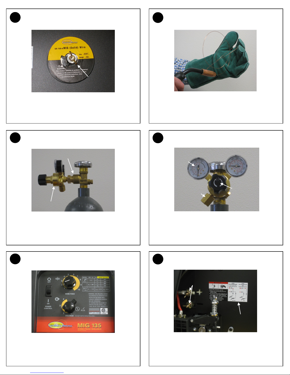
INSTALLING A 4” SPOOL OF WIRE 2INSTALLING A 8” SPOOL OF WIRE
5SLIDE MIG GUN INTO WIRE FEEDER 6TIGHTEN RETAINING SCREW FOR MIG GUN
9FEED WIRE - CLOSE TENSION ARM 10 FEED WIRE - REMOVE GUN TIP & NOZZLE
Remove wing nut, washer and black bushing. Slide on spool so
wire feeds off the bottom of spool. Reinstall bushing, washer and
wing nut. See Step 13 to adjust wire spool tension.
Remove wing nut, washer and black bushing. Slide on spool
adapter. Reinstall bushing, washer and wing nut. Slide on 8”
spool of wire. Knob on spool adapter slides into hole on side of
8” spool of wire. See Step 13 to adjust wire spool tension.
Remove Retaining Screw (see step 6) Slide the machine end of
the MIG gun into the front panel receptacle. Push it all the way
into the wire feeder as far as it will go. Feed trigger leads through
the opening in the front panel.
Tighten the retaining screw on the wire feeder housing to secure
the gun. Install trigger leads into the trigger lead receptacle.
Close the drive roll tension arm. Apply tension to the wire by
turning the wing nut clockwise on the Drive Roll Tension Adjust-
ment. Do not overtighten. See Step 14.
To finish feeding the wire through the MIG gun, you will need to
remove the gun nozzle and tip.
4 In.
Spool
Wing
Nut
Knob
8 In.
Spool
Adapter
Trigger
Lead
Opening
Retaining
Screw
Trigger
Lead
Recpt.
Tension
Adjustment

3DRIVE ROLL GROOVE SELECTION 4MIG GUN - MACHINE END
7FEED WIRE - OPEN TENSION ARM 8FEED WIRE - THREAD WIRE
11 FEED WIRE - PULL TRIGGER TO FEED WIRE 12 FEED WIRE - REINSTALL TIP AND NOZZLE
The smaller groove on the drive roll is to be used with .023 wire.
The larger groove can be used for .030 and .035 wire. Use the
supplied “L” shaped hex wrench to loosen set screw and to align
the proper groove to the wire path. Retighten set screw.
This MIG gun is a one piece connection. Notice the retaining
groove on the machine end. The hex-headed retaining screw in
the step (6) will set down into this groove.
Open the drive roll tension arm on the wire feeder. Feed the loose end of the wire through the Inlet Guide Tube, past
the drive roll and into the back of the MIG Gun. Keep tension on
the wire to prevent unspooling on the spool. Make certain wire is
centered on groove and adjust drive roll (Step 3) if needed.
Stretch out the MIG gun. Turn on input power and pull the trigger
to feed the wire through the gun. Stop when the wire pushes
through the end of the gun.
Slide the correct size contact tip for the wire size you are using
over the end of the wire and tighten clockwise to secure. Choose
the correct nozzle, thread on nozzle and clip any excess wire.
.023
.030
.035
Set
Screw
Retaining
Groove
Flux-Cored Nozzle
Hard Wire
Nozzle
Drive Roll
Tension
Arm
13 ADJUSTING SPOOL TENSION 14 ADJUSTING DRIVE ROLL TENSION
15 INSTALL SHIELDING GAS 16 SET GAS FLOW
17 SETTING FRONT PANEL CONTROLS 18 SETTING POLARITY - CHECK WIRE TYPE
Adjust the wing nut in the center of the spool to adjust spool ten-
sion. A small amount of slack should be in the weld wire when
wire feeding stops. Too much tension will cause poor feeding.
Too little tension will cause the wire on the spool to uncoil.
Test drive roll tension by feeding wire into a gloved hand from
about 4 inches away. Loosen tension to apply little pressure.
Slowly increase tension until the wire coils up in your hand with-
out slipping in the drive rolls.
Thread the regulator directly to the bottle. A CO2 adapter will be
needed if using straight CO2 gas. One end of the supplied gas
hose connects to the regulator. The other end connects to the gas
valve on the back of the machine.
Open the drive roll tension arm on the wire feeder. Open the
valve on the shielding gas bottle. Turn on the unit power and pull
the trigger. Adjust the regulator to set for 20 cubic feet per min-
ute. Reinstall the drive roll tension arm on the wire feeder.
On the wire compartment access panel is a set-up guide. Find the
type of material being welded and the size of wire you are using.
Slide over to the thickness of the thinnest material you are weld-
ing. Set the voltage and wire feed speed on the front of the unit.
Feed ground cable through the front opening. Install on the open
polarity terminal. Solid wire uses Electrode Positive (DCEP) po-
larity. Flux-cored wire use Electrode Negative (DCEN) polarity.
See polarity label in the wire compartment and change as needed.
Tighten
Clockwise
Polarity
Terminals
Polarity
Label
20
CFH
Connect
Gas Hose Increase
Clockwise
Regulator
Threaded Connection
Popular Welding System manuals by other brands

Lincoln Electric
Lincoln Electric POWER WAVE 405 IM746 Operator's manual

Parkside
Parkside PISG 80 A1 Assembly, operating, and care manual

Ritmo
Ritmo ELEKTRA 400 Operator's manual

Linde
Linde Ryval 251 aXe instruction manual

ESAB
ESAB Mig 300i instruction manual

Miller
Miller Big Blue 300 PRO Series owner's manual


