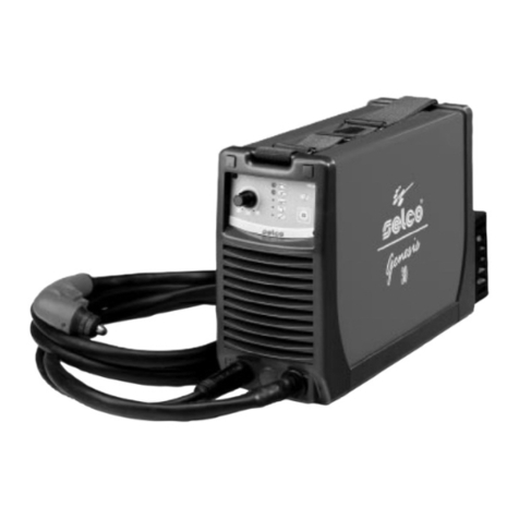
Sel Genesis 90 Operating instructions

REPAIRS MANUAL
Genesis
90
E
N
G
L
I
S
H

Code: 92.08.003
Edition: 05/05
Rev.: 1.0
SELCO s.r.l.
Via Palladio, 19
I - 35010 ONARA DI TOMBOLO (Padova) Italy
Tel. +39 049 9413111
Fax +39 049 9413311
e-mail: [email protected]
How to contact Selco Service Department:
SELCO s.r.l.
Service Department
c/o SELCO 2
Via Macello, 61
I - 35010 CITTADELLA (Padova) Italy
Tel. +39 049 9413111
Fax +39 049 9413311
e-mail: [email protected]
All translation, reproduction and adaptation rights, total or partial and by any means (including photostat copies, films and micro
films), are reserved and forbidden without the written authorisation of Selco S.r.l.
INDEX :
1) PURPOSE OF THE MANUAL . . . . . . . . . . . . . . . . . . . . . . . . . . . . . . . . . . . . . . . . . . . . . . . . . . . . . . . . . . . . . . .3
2) WARNINGS, PRECAUTIONS AND GENERAL NOTICES FOR PERFORMING REPAIRS . . . . . . . . . . . . . . . . . . . . .4
3) INSTRUMENTS AND CONVENTIONS FOR PERFORMING DIAGNOSIS AND REPAIR . . . . . . . . . . . . . . . . . . . . .5
4) DESCRIPTION OF OPERATION OF THE POWER SOURCES . . . . . . . . . . . . . . . . . . . . . . . . . . . . . . . . . . . . . . .7
5) OPERATING PRINCIPLE - BLOCK DIAGRAM . . . . . . . . . . . . . . . . . . . . . . . . . . . . . . . . . . . . . . . . . . . . . . . . . . .15
6) WIRING AND CONNECTION DIAGRAM . . . . . . . . . . . . . . . . . . . . . . . . . . . . . . . . . . . . . . . . . . . . . . . . . . . . . .16
7) PC BOARDS’ LOCATION . . . . . . . . . . . . . . . . . . . . . . . . . . . . . . . . . . . . . . . . . . . . . . . . . . . . . . . . . . . . . . . . . .18
8) DESCRIPTION OF DIAGNOSTIC INDICATIONS . . . . . . . . . . . . . . . . . . . . . . . . . . . . . . . . . . . . . . . . . . . . . . . .20
9) SETUP PARAMETERS . . . . . . . . . . . . . . . . . . . . . . . . . . . . . . . . . . . . . . . . . . . . . . . . . . . . . . . . . . . . . . . . . . . . .25
10) DESCRIPTION, TESTING AND REPLACEMENT OF THE ELECTRONIC BOARDS, CURRENT CALIBRATION . . . .26
10.1) Input filter PC board 15.14.269 . . . . . . . . . . . . . . . . . . . . . . . . . . . . . . . . . . . . . . . . . . . . . . . . . . . . . . .28
10.2) Power supply PC board 15.14.271 . . . . . . . . . . . . . . . . . . . . . . . . . . . . . . . . . . . . . . . . . . . . . . . . . . . . .30
10.3) Power inverter PC board 15.14.176 . . . . . . . . . . . . . . . . . . . . . . . . . . . . . . . . . . . . . . . . . . . . . . . . . . . .32
10.4) Resonant inverter control PC board 15.14.152 . . . . . . . . . . . . . . . . . . . . . . . . . . . . . . . . . . . . . . . . . . . .35
10.5) Inveter driver PC board 15.14.200 . . . . . . . . . . . . . . . . . . . . . . . . . . . . . . . . . . . . . . . . . . . . . . . . . . . . .36
10.6) Output filter PC board 15.14.276 . . . . . . . . . . . . . . . . . . . . . . . . . . . . . . . . . . . . . . . . . . . . . . . . . . . . . .37
10.7) Secondary rectifier and pilot arc PC board 15.14.277 . . . . . . . . . . . . . . . . . . . . . . . . . . . . . . . . . . . . . .38
10.8) HF PC board 15.14.192 . . . . . . . . . . . . . . . . . . . . . . . . . . . . . . . . . . . . . . . . . . . . . . . . . . . . . . . . . . . . . .39
10.9) Control panel PC board 15.22.131 (15.14.259 PC board + FP131) . . . . . . . . . . . . . . . . . . . . . . . . . . . . .40
10.10) Output current calibration (delivered and displayed) . . . . . . . . . . . . . . . . . . . . . . . . . . . . . . . . . . . . .42
11) AVAILABLE SPARE PARTS . . . . . . . . . . . . . . . . . . . . . . . . . . . . . . . . . . . . . . . . . . . . . . . . . . . . . . . . . . . . . . . . .44
2

Purpose of the manual 3
1) PURPOSE OF THE MANUAL
This manual is designed to provide authorised service centres
with the basic information necessary for performing repairs on
the models Genesis 90.
In order to avoid serious injury to persons or damage to things,
this manual must be used only by qualified technicians.
Selco S.r.l. accepts no liability for any injury to persons or dama-
ge to things that may occur during performance of repairs, even
after reading or practical application of this manual.
For a detailed description of the operation, use and ordinary
maintenance of the machine, please refer to the "Instructions for
use and maintenance manual" which must always accompany
the machine. The purchaser must follow the directions contai-
ned in the above manual. Failure to do so will exempt Selco
from all liability.
The operations described in this manual require the use of a
digital multimeter, an DC ammeter clamp and a basic knowled-
ge of how the machine works. Basic electrotechnical knowled-
ge is also required.
Repair consists in identification of the faulty part, included in
the list of available spare parts, and replacement of it.
In the event of failure of an electronic board, repair entails
replacement of the board and not replacement of the faulty
electronic component on the board.
For troubleshooting advice, see introduction to
chapter 10.
Do not carry out modifications or maintenance not scheduled
in this manual.
If the problem cannot be solved by following the instructions
provided in this manual, contact the Selco Service Department
or send the machine to Selco for repair.

4 Warnings, precautions and general notices for performing repairs
2) WARNINGS, PRECAUTIONS AND GENERAL
NOTICES FOR PERFORMING REPAIRS
Repairs must be performed by qualified personnel only.
Before performing the repair, you should read and assimilate the
contents of this manual, in particular the safety precautions.
Avoid performing repairs without the presence of another person
able to provide help in the event of an accident.
The repair of a machine requires access to its internal parts and con-
sequently removal of some of the protective panels. Additional pre-
cautions are therefore necessary with respect to use of the machi-
ne for welding in order to prevent possible injury or damage cau-
sed by contact with
- live parts
- moving parts
- parts at high temperature
Live parts:
CAUTION ! When handling internal parts of the
machine, remember that opening of the switch does
not prevent the risk of electric shocks: the machine
must be unplugged from the power supply.
Wait approx. one minute before carrying out work on the
internal parts as the capacitors may be loaded at high voltage.
CAUTION ! When taking measurements, remem-
ber that the measuring instruments can be live and
you should therefore avoid touching their metal
parts.
ATTENTION ! : When the torch button is pressed,
the machine generates a series of high voltage
impulses (10,000 V ca) to strike the pilot arc.
Therefore, if an arc striking test is not required
during the diagnostic phases, we recomment CN2 is discon-
nected from the HF 15.14.192 board!
Once the repair has been carried out, remember to recon-
nect CN2 to the HF 15.14.192 board before closing the
machine and then perform some striking and cutting tests.
Moving parts:
CAUTION ! Keep your hands well away from the
fan when the machine is connected to the power
supply. Ensure that the machine is unplugged and
that the fan is at a standstill before replacing it.
Parts at high temperature:
CAUTION ! When handling internal parts of the
machine, remember that some of them may be
very hot. In particular avoid contact with heat
sinks.

Instruments and conventions for performing diagnosis and repair 5
3) INSTRUMENTS AND CONVENTIONS FOR PERFOR-
MING DIAGNOSIS AND REPAIR
3.1) Instruments for basic diagnosis
The following are required:
- a multimeter w
ith the following scales:
Ohm: from 0 to a few Mohm
Diode testing
Direct voltage (Vdc): from mVdc to 700 Vdc
Alternating voltage (Vac): from 10 Vac to 500 Vac
NOTE: You are advised to use an instrument with
automatic scale since it is not theoretically possible to
predict the electrical quantity to be measured when
the machine has broken down.
- an DC ammeter clamp at least in class 2.5 with e.o.s. 100A pk
- alternatively to the ammeter clamp, a shunt can be used with
value 60 mV @ 100 A.
NOTES:
* remember that other types of shunts can also be used,
but accuracy is reduced with higher capacities, whe-
reas with lower capacities the measurement must be
taken quickly to avoid overheating of the shunt
* once fitted, the shunt can be at dangerous potentials!
* the ammeter clamp is preferable as it is more practical
3.2) Repair tools
- complete set of fork spanners
- complete set of pipe spanners for hexagonal nuts
- complete set of blade screwdrivers
- complete set of Phillips screwdrivers
- complete set of Allen keys
- Phillips torque screwdriver for M3 screws with tigh-
tening torque adjustable range from 1 to 3 Nxm,
accuracy 0.1 Nxm
- crimper for insulated wire terminals (blue, red and
yellow)
- pliers for AMP contacts
- tweezers and cutting nippers - type commonly used
for electronic components
- tongs (dimensions suitable for closing gas pipe
clamps)
- welder for electronic components, minimum power
50 W
- portable electric drill
3.3) Grid load
Use of grid load can speed up fault tracing and machine testing.
Just remember that a fixed power resistor applied to machine's
output is somewhat equivalent to a welding arc, but only inside
of a narrow output voltage range, whose center value can be
determined by the formula:
PLASMA CUTTING:
V OUT 80 + 0.4 x I OUT
Es.: 100Vdc @ 50A
116Vdc @ 90A
etc.
If output voltage goes too much above or below the rated value,
the generator could either saturate and in both cases real out-
put current could be much different from expected value.
Grid load resistor's rated power is also important, 'cos a 116Vdc
@ 90A grid load produces 10kW to be dissipated by air cooling.
So, when using grid load, pay attention to both out-
put current & output voltage and use correct resi-
stance value & power!

6 Instruments and conventions for performing diagnosis and repair
3.4) Conventions
By convention, when a measurement has to be taken between
two points, for example ab, the arrow point indicates
where to apply the red tip of the multimeter (a),while the black
tip is applied at the other end (b).
When a double arrow appears between two measuring points
(e.g.: cd), the voltage to be measured is alternating (nor-
mally at 50 Hz), therefore it does not matter in which order the
multimeter terminals are applied.
In drawings and tables, when a voltage measurement appears
referring to terminals of components such as DIODES, BJT,
MOSFET and IGBT, the multimeter is used in "diode test" mode
(these measurements are always taken with the machine swit-
ched off and normally give values in the range +0.10 … +0.90
Vdc). In this case the following symbol is affixed beside the
value to be measured
Junction measurement (multimeter in "diode test" mode)
The following symbols will be used in the same way:
AC or DC voltage measurement (multimeter in voltmeter
mode)
Resistance measurement (multimeter in ohmmeter mode)
Current measurement (ammeter clamp or shunt + multi-
meter in millivoltmeter mode)
The measuring conditions (power source on/off etc.) are always
clearly indicated beside the values to be measured.
The connector terminals are indicated by the name of the con-
nector followed by a slash and the number of the terminal; for
example CN1/2 indicates terminal 2 of connector CN1.
Unless otherwise specified, all the measurements must be per-
formed with the boards fitted, together with their connections.
This manual refers to the last updated version of
the power sources and component electronic
boards. As the modifications introduced are very
slight, there should be no problem in identifying
the corresponding points to be tested also in the
boards of the previous version. In the event of difficulty, con-
tact Selco Service.
Remember that the first of the tests to be perfor-
med is the VISUAL CHECK!
The visual check reduces troubleshooting times
and directs any subsequent tests towards the
damaged part!

4.1 SAFETY
Prior to performing any operation on the machine, make sure that you
have thoroughly read and understood the contents of this manual.
Do not perform modifications or maintenance operations which are
not prescribed.
For any doubt or problem regarding the use of the machine, even if not
described herein, consult qualified personnel.
The productor cannot be held responsible for damage to persons or
property caused by the operator's failure to read or apply the contents
of this manual.
4.1.1 Operator and other persons’ protection
The welding (cutting) process is a noxious source of radiations, noise,
heat and gas emissions. Persons fitted with pacemakers must consult
their doctor before undertaking arc welding or plasma cut operations.
If the above prescription is not observed, the manufacturer accepts
no liability for any damages sustained in the event of an accident.
Personal protection:
- Do not wear contact lenses!!!
- Keep a first aid kit ready for use.
- Do not underestimate any burning or injury.
- Wear protective clothing to protect your skin from the arc rays,
sparks or incandescent metal, and a helmet or a welding cap.
- Wear masks with side face guards and suitable protection filter (at
least NR10 or above) for the eyes.
- Use headphones if dangerous noise levels are reached during the
welding (cutting).
Always wear safety goggles with side guards, especially during the
manual or mechanical removal of welding (cutting) slags.
lf you feel an electric shock, interrupt the welding (cutting) ope-
rations immediately.
Other persons’ protection:
- Position a fire-retardant partition to protect the surrounding area
from rays, sparks and incandescent slags.
- Advise any person in the vicinity not to stare at the arc or at the
incandescent metal and to get an adequate protection.
- lf the noise level exceeds the limits prescribed by the law, delimit
the work area and make sure that anyone getting near it is pro-
tected with headphones or earphones.
4.1.2 Fire/explosion prevention
The welding (cutting) process may cause fires and/or explosions.
- Compressed gas cylinders are dangerous; consult the supplier
before handling them.
Protect them from:
- direct exposure to sun rays;
- flames;
- sudden changes in temperature;
- very low temperatures.
Compressed gas cylinders must be fixed to the walls or to other
supports, in order to prevent them from falling.
- Clear the work area and the surrounding area from any
infiammable or combustible materials or objects.
- Position a fire-fighting device or material near the work area.
- Do not perform welding or cutting operations on closed contai-
ners or pipes.
- lf said containers or pipes have been opened, emptied and care-
fully cleaned, the welding (cutting) operation must in any case be
performed with great care.
- Do not weld (cut) in places where explosive powders, gases or
vapours are present.
- Do not perform welding (cutting) operations on or near contai-
ners under pressure.
- Don’t use this machine to defrost pipes.
4.1.3 Protection against fumes and gases
Fumes, gases and powders produced during the welding (cutting)
process can be noxious for your health.
- Do not use oxygen for the ventition.
- Provide for proper ventilation, either natural or forced, in the
work area.
- In case of welding (cutting) in extremely small places the work of
the operator carrying out the weld should be supervised by a col-
league standing outside.
- Position gas cylinders outdoors or in places with good ventilation.
- Do not perform welding (cutting) operations near degreasing or
painting stations.
4.1.4 Positioning the power source
Keep to the following rules:
- Easy access to the equipment controls and connections must be
provided.
- Do not position the equipment in reduced spaces.
- Do not place the generator on surfaces with inclination excee-
ding 10° with respect to the horizontal plane.
4.1.5 lnstalling the apparatus
- Comply with the local safety regulations for the installation and carry
out the maintenance service of the machine according to the con-
structor's directions.
- Any maintenance operation must be performed by qualified per-
sonnel only.
- The connection (series or parallel) of the generators is prohibited.
- Before operating inside the generator, disconnect the power supply.
- Carry out the routine maintenance on the equipment.
- Make sure that the supply mains and the earthing are sufficient and
adequate.
- The earth cable must be connected as near the area to be welded
(cut) as possible.
- Take the precautions relevant to the protection degree of the power
source.
- Before welding (cutting) , check the condition of the electric cables
and of the torch, and if they are damaged repair or change them.
- Neither get on the material to be welded (cut), nor lean against it.
- The operator must not touch two torches or two electrode hol-
ders at the same time.
4.1.6 Precautions against risks connected with the use
of compressed air
Connect the air supply to the coupling provided, making sure pres-
sure is at least 6 bars (0.6 MPa) with a minimum flow rate of 200
l/min. If the air supply comes from pressure reducer of a compres-
sor or a central system, the reducer must be set to the maximum
outlet pressure that must not, however, exceed 8 bars (0.8 MPa). If
the air supply comes from a compressed air canister it must be
equipped with a pressure regulator.
A compressed air canister must never be directly
coupled to the machine pressure reducer. Pressure
might exceed the capacity of the reducer which might
consequently explode.
The manufacturer accepts no liability if the above prescription is
not duly observed and complied with at all times.
Description of operation of the power sources 7
WARNING
4) DESCRIPTION OF OPERATION OF THE POWER SOURCES
Use and routine maintenance (excerpt from the "Instructions for use" manual provided with each power source).

4.2 ELECTROMAGNETIC COMPATIBILITY (EMC)
This device is built in compliance with the indications contained
in the harmonized standard EN60974-10, to which the opera-
tor must refer for the use of this apparatus.
- lnstall and use the apparatus keeping to the instructions
given in this manual.
- This device must be used for professional applications
only, in industrial environments It is important to remem-
ber that it may be difficult to ensure the electromagnetic
compatibility in other environments.
4.2.1 Installation, use and area examination
- The user must be an expert in the sector and as such is
responsible for installation and use of the equipment accor-
ding to the manufacturer's instructions. lf any electromagnetic
disturbance is noticed, the user must soave the problem, if
necessary with the manufacturer's technical assistance.
- In any case electromagnetic disturbances must be reduced
until they are not a nuisance any longer.
- Before installing this apparatus, the user must evaluate the
potential electromagnetic problems that may arise in the
surrounding area, considering in particular the health con-
ditions of the persons in the vicinity, for example of per-
sons fitted with pacemakers or hearing aids.
4.2.2 Emission reduction methods
MAINS POWER SUPPLY
- The welding power source must be connected to the
supply mains according to the manufacturer's instructions.
In case of interference, it may be necessary to take further pre-
cautions like the filtering of the mains power supply.
lt is also necessary to consider the possibility to shield the power
supply cable.
WELDING POWER SOURCE MAINTENANCE
The welding power source needs routine maintenance accor-
ding to the manufacturer's instructions.
When the equipment is working, all the access and operating
doors and covers must be closed and fixed.
The welding power source must not be modified in any way.
WELDING AND CUTTING CABLES
The welding (cutting) cables must be kept as short as possible,
positioned near one another and laid at or approximately at
ground level.
EQUIPOTENTIAL CONNECTION
The earth connection of all the metal componente in the wel-
ding (cutting) installation and near it must be taken in conside-
ration.
However, the metal componente connected to the work-piece
will increase the risk of electric shock for the operator, if he tou-
ches said metal componente and the electrode at the same
time.
Therefore, the operator must be insulated from all the earthed
metal componente.
The equipotential connection must be made according to the
national regulations.
EARTHING THE WORKPIECE
When the workpiece is not earthed for electrical safety reasons
or due to its size and position, the earthing of the workpiece
may reduce the emissione. It is important to remember that the
earthing of the workpiece should neither increase the risk of
accidents for the operators, nor damage other electric equip-
ment.
The earthing must be made according to the national regula-
tions.
SHIELDING
The selective shielding of other cables and equipment present
in the surrounding area may reduce the problems due to inter-
ference. The shielding of the entire welding (cutting) installation
can be taken in consideration for special applications.
8Description of operation of the power sources
WARNING
4.3 RISK ANALYSIS
Risks posed by the machine
Risk of wrong installation.
Electrical risks.
Risks connected with electromagnetic disturbances produ-
ced by the welding power source and induced on the wel-
ding power source.
Solutions adopted to pervent them
A manual with the instructions for use has been pro-
duced for this purpose.
Application of the EN 60974-1 Standard.
Application of the EN 60974-10 Standard.

Description of operation of the power sources 9
The contents of this chapter are of vital importance and the-
refore necessary for operation of the warranties. The manu-
facturer accepts no liability if the operator fails to observe
the above precautions and instructions.
4.4 WELDER PRESENTATION
Genesis 60 and Genesis 90 are handy compact plasma cut
power sources.
Genesis 60 and Genesis 90 use compressed air only, which can
be supplied by an ordinary compressor or a suitably sized cen-
tral system; they are able to inexpensively perform good quality
cuts up to a thickness of 20 mm for Genesis 60 and 30 mm for
Genesis 90 on carbon steel while maintaining limited weight
and dimensions.
The excellent performance/weight ratio has been made possible
by use of the inverter technology, common to the whole of the
Genesis range. The current is stable and insensitive to variations
in mains voltage, in the height of the cutting arc, in the feed
speed and in the thickness of the metal to be cut. The Genesis
60 and Genesis 90 are provided with an automatic pilot arc re-
striking circuit which ensures optimal cutting of metal grille
structures.
The welder features safety systems that inhibit the power circuit
when the operator comes into contact with live parts of the
machine, and controls to reduce the wear on the electrode and
nozzle when the cutting arc is struck. The pilot arc is struck by
means of a high frequency voltage discharge which is automati-
cally disconnected once the operation has been performed,
thus limiting the emission of radio interference in the rest of the
cutting procedure.
The following are provided on the power source:
- a torch fitting
- a ground socket
- a front panel
- a rear panel.
4.4.1 Front control panel
Fig.1
*
L1 : Voltage warning light green led.
Comes on with the start switch (Fig.2) "I1" in position "I" and
indicates that the plant is on and there is voltage.
* L2: Power output light red led.
Comes on when the arc is sparked, both during cutting and
when not cutting, and goes out as soon as the arc finishes.
* L3: torch cap alarm green led.
Means that the torch cap has not been properly tightened.
The generator has no power output.
* L4: compressed air alarm green led.
Means that the pressure of compressed air is below 3 bar, too
low for proper functioning. The generator has no power output.
*L5 : Safety device warning light yellow led.
lndicates that the safety devices like thermal cutout.
With "L5" on, the power source remains connected to the
supply mains, but does not supply output power.
"L5" remains on until the fault has been removed and in any
case until the inner temperatures are not within the normal
values; in this case it is necessary to leave the power source
on to exploit the operating ventilator and reduce the time
when it is not active.
* E1: Encoder for setting the cutting current.
Allows you to continuously adjust the cutting current. This
current stays unchanged during cutting when the supply and
cutting conditions vary within the allowed ranges.
* T1 : VOLT-AMP reading selection key.
Its permits display of either the welding voltage or current on
DISPLAY “D1”.
If LED “V” is on, the last voltage reading taken during the last
cutting operation is displayed. If you do not begin cutting
within 5 sec. the system automatically switches to A, displa-
ying the set current. Vice versa if you begin cutting within 5
sec., the voltage is displayed during the entire cutting opera-
tion after which the reading remains displayed for a further 5
seconds.
If LED “A” is lit up on display D1, the set or cutting current is
displayed if the operation is in progress. The display is main-
tained for 5 seconds after the end of the operation.
* T2: gas test pushbutton.
Allows impurities to be removed from the compressed air cir-
cuit and preliminary capacity and pressure settings to be
made with no power output.
* D1 : displays the set current, cutting current and cutting vol-
tage or the letters GEN (at switch-on) and ERR (blinking in the
event of an alarm).
* D2 : displays the air pressure value for the cutting process. At
switch-on it displays the software version. In the event of an
alarm, it displays the alarm code in blinking mode:
01 IIC error
02 torch cap open
03 air pressure too low
11 thermal switch
In the event of an alarm, the operating conditions
are restored only if the cause is removed.

4.4.2 Rear control panel
*I1: Off/On switch
Turns on the electric power to the welder.
It has two positions, "O" off, and "I" on.
* With the I1 switch in the "I" on position, the welder is
operational.
* The welder is connected to the mains supply even if the I1
switch is in the "O" position, and therefore there are elec-
trically live parts inside it. Carefully follow the instruc-
tions given in this manual.
* 1 : Supply cable.
* F1 : Pressure adjustment knob
* P1 : Filter unit air connection 1/4 ” coupling
* F : Air filter unit
Fig.2
4.4.3 Technical characteristics
G90
Power supply voltage
(50/60 Hz) 3x400V
Delayed fuse 32 A
Rated power 11.98 kW
Cutting current
(x=60%) 90 A
(x=100%) 70 A
Cutting voltage 116 V
No-load voltage 265 V
Pilot arc current 22 A
Gas type AIR
Operating pressure 5 bar
Flow rate 180 l/min
Torch to be used 81.20.037
Protection class IP23C
Insulation class H
Construction regulations EN60974-1
EN60974-10
Dimensions (LXPXH) 215x596.5x406 mm
Generator weight 25 Kg
Above data are referred to environment al 40°C
4.5 TRANSPORT - UNLOADING
Never underestimate the weight of the equip-
ment, (see technical characteristics).
Never make the cargo pass or leave it suspended
over people or things.
Neither let the equipment or the single unit fall,
nor put it down with force.
Once it has been removed from the packing, the
power source is supplied with an extendible belt
which can be used to move it in the hand or on
the shoulder.
4.6 INSTALLATION
Choose an adequate installation area by following
the criteria provided in Section "4.1 SAFETY" and
“4.2 ELECTROMAGNETIC COMPATIBILITY
(EMC)”.
Do not position the power source and the equip-
ment on surfaces with inclination exceeding 10°
with respect to the horizontal plane.
Protect the installation from heavy rain and sun.
4.6.1 Electric connection to the supply mains
The equipment is provided with a single electric connection with
a 5m cable positioned in the rear part of the power source.
Size table of the power source input cables and fuses:
Power source GENESIS 90
Rated voltage 400 V ±15%
Voltage range 340 - 460 V
Delayed fuses 32 A 500 V
Power supply cable 4x6 mm2
* The electrical system must be made by skilled technicians
with the specific professional and technical qualifications
and in compliance with the regulations in force in the
country where the equipment is installed.
* The welding power source supply cable is provided with a
yellow/green wire that must ALWAYS be earthed. This yel-
low/green wire must NEVER be used with other voltage con-
ductors.
* Verity the existence of the earthing in the used plant and
the good condition of the socket/s
* lnstall only plugs that are homologated according to the
safety regulations.
10 Description of operation of the power sources
WARNING
WARNING

Description of operation of the power sources 11
4.6.2 Connecting the equipment components
Keep to the safety regulations contalned in sec-
tion “4.1SAFETY”.
Connect the componente carefully, in order to
avoid power losses.
4.7 SETTING UP
For installation of the system, follow the instructions below:
1. Place the generator in a dry, clean place with suitable ventila-
tion.
2. Connect up the compressed air supply with a 1/4 inch to the
air inlet P1 in the filter unit F (Fig.2). The pressure must ensure
at least 5 bars with a flow rate of at least 200 litres a minute.
Securely connect the earth cable connector to the generator as
shown in figure 4.
3. Position the earthing clamp onto the piece to be cut, ensuring
that it makes a good electric connection (Fig. 4).
4. Check that all the components of the torch are present and cor-
rectly fitted and connect the torch fitting to the connector on
the generator as shown in figure 3.
Insert the male fitting (torch side) into the corresponding fema-
le fitting (machine side). Align the locating tooth (A) on the hou-
sing and insert the ring nut (B) which must be compatible.
To permit screw-tightening of the ring nut (B), the tool provided
(D) must be first inserted and pressed into the hole (C) in order
to release the anti-rotation lock. This operation must be perfor-
med until the ring nut has been completely tightened. To di-
sconnect the torch, first release the anti-rotation lock by inser-
ting the tool provided (D) into the hole (C).
Fig. 3
5. Switch on the system, ensuring the LED's are working cor-
rectly and some display.
If operating faults occur in the generator it will be inhibited
until normal operating conditions are restored. Press the gas
test pushbutton (T2 in Fig 1) in order to remove residual
impurities from the compressed air circuit, then lift and turn
the knob to adjust the pressure (F1 Fig.2) until the display D2
shows a pressure reading of 5 bars (carry out the operation
keeping the gas test button pressed down, so as to make the
adjustment with air circulating in the piping).
6. Set the value of the cutting current with the potentiometer,
keeping in mind the thickness to be dealt with.
7. Press for a moment the torch button so as to generate the
pilot arc; release the control, checking the machine is cor-
rectly operating with the display panel. It is advisable not to
keep the arc lit to no purpose without making contact, so as
to prevent wear on the electrode and the nozzle. If you con-
tinue to use it like this the apparatus itself will turn off the
pilot light after about 6 seconds.
In the case where a fault is found during the above phases,
check the LED's, the display and if necessary consult the
chapter "Possible electrical faults" in the manual.
Fig. 4
4.8 PROBLEMS - CAUSES
4.8.1 Possible cutting defects
Fault
Insufficient penetration
The cutting arc goes out
Substantial burr formation
Nozzle overheating
Cause
- Cutting speed too high
- Current set too low
- Earth clamp with inefficient
contact
- Thickness of piece excessive
- Electrode, nozzle or diffuser
worn
- Air pressure too high
- Cutting speed too low
- Insufficient air flow
- Defective pressure switch
- Supply voltage too low
- Inadequate air pressure
- Cutting speed too low
- Nozzle eroded
- Electrode eroded
- Insufficient air quantity

4.8.2 Possible electrical failures
See also chapter 4.4.1 for problems with alarm code.
If you have any doubts or problems, do not hesitate to con-
sult your nearest technical service centre.
4.9 NECESSARY ROUTINE MAINTENANCE
Prevent metal powder from accumulating near the aeration fins
and over them.
Disconnect the power supply before every opera-
tion!
Carry out the following periodic controls on the
power source:
* Clean the power source inside by means of low-
pressure compressed air and soft bristel brushes.
* Check the electric connections and all the connec-
tion cables.
For the maintenance or replacement of torch com-
ponente and/or earth cables:
* Disconnect the power supply before every operation.
* Check the temperature of the componente and make
sure that they are not overheated.
* Always use gloves in compliance with the safety stan-
dards.
* Use suitable spanners and tools.
* For torch maintenance, keep carefully to the directions
shown under instructions for use of the torch enclosed with
this manual.
Note: Failure to perform said maintenance will invalidate all
warranties and exempt the manufacturer from all liability.
4.10 THEORETICAL OUTLINE OF PLASMA CUTTING
A gas assumes the plasma state when it is brought to an extre-
mely high temperature and ionizes wholly or partly, thus beco-
ming electrically conductive.
Although the plasma exists in every electric arc, by the term
"plasma arc" we refer specifically to a torch for welding or cut-
ting that uses an electric arc, made to pass through the constric-
ting neck of a suitable nozzle, to heat a gas coming out of this,
so as to take it to the plasma state.
Fig. 5 Manual plasma cutting plant
4.10.1 Plasma cutting process
The cutting action is obtained when the plasma arc, made very
hot and highly concentrated by the design of the torch, transfers
onto the conductive piece to be cut, closing the electrical circuit
with the generator. The material is first melted at a high tempe-
rature of the arc, and then removed by the high exit velocity of
the ionized gas from the nozzle.
The arc can have two different states: that of the transferred arc,
when the current passes through the piece to be cut, that of the
pilot arc or non-transferred arc, when this is sustained between
the electrode and the nozzle.
4.11 CUTTING SPECIFICATIONS
In plasma cutting, the thickness of the material to be cut, the
speed of cutting and the current supplied by the generator have
values which are related to each other; these depend on the
type and quality of the material, type of torch as well as the type
and condition of the electrode and nozzle, distance between
nozzle and piece, pressure and impurity of the compressed air,
cut quality required, temperature of the piece to be cut, etc.
In the diagrams as in Fig. 6, 7, 8 we can see that the thickness
to be cut is inversely proportional to the cutting speed, and that
both these values can be increased with an increase in current.
12 Description of operation of the power sources
Fault
Apparatus fails to come on
(Yellow LED L1 off)
Pilot arc fails to ignite (with
yellow LED L1 on)
Pilot arc fails to ignite (with
yellow LED L1 and red LED
L3 on)
Fails to transfer from pilot arc
to cutting arc
Lack of power output
Cause
- Incorrect mains supply
- Break in the contacts of the
torch button (check the con-
nection of the torch attach-
ment is working after having
cut off the power supply)
- Torch parts subject to wear
out of action
- Air pressure too high
- Possible problems in control
circuits
- Possible problems in control
circuits
- Arc sensors faulty
- Protective devices triggered
(see chapter on
"Functions of controls")
- Possible problems in control
circuits

Description of operation of the power sources 13
GENESIS 90
MILD STEEL
STAINLESS STEEL
ALUMINIUM
* High quality cut
Fig. 6
Fig. 7
Fig. 8
4.12 RATING PLATE
Thickness (mm)
1
3
1
3
6
10
15
1
3
6
10
15
20
25
30
Current (A)
30
30
60
60
60
60
60
90
90
90
90
90
90
90
90
Speed (mm/min)
2500
500
14000
3200
1200*
900
400
21000
7200
3200
1400
900
400*
250*
200
Thickness (mm)
1
3
1
3
6.5
10
15
1
3
6.5
10
15
20
25
30
Current (A)
30
30
60
60
60
60
60
90
90
90
90
90
90
90
90
Speed (mm/min)
5700
1000
15000
5200
2300*
1200
650
20000
8400
4500
2200
1400
900*
500*
250
Thickness (mm)
1
3
6
1
3
6
10
15
1
3
6
10
15
20
25
30
35
Current (A)
30
30
30
60
60
60
60
60
90
90
90
90
90
90
90
90
90
Speed (mm/min)
3400
950
450
12000
3300
1550*
850
500
20000
6300
3200
1500
900
650*
400*
250*
160

14 Description of operation of the power sources
A-90 TORCH
4.13 TECHNICAL CHARACTERISTICS
4.14 INSTALLATION
Turn off the generator.
Connect the torch attachment to the correponding coupling on
the generator by completely screwing on the locking ring.
4.15 SETTING UP FOR USE
Fig.1 Torch body assembly
Before starting work, it is necessary to carry out the following
checks and work:
1) Check that the generator is turned off.
2) Check that all the parts of the torch are working. For the various
parts that make up the torch body (Fig.1), the sequence of cor-
rect assembly is 1-2-3-4-5-6.
3) To fit the electrode (No.2), use the key, taking care to avoid
excessive tightening that could damage the thread of the com-
ponents.
The electrode must be unscrewed only after the post-cutting air
flow is finished, and therefore with the electrode itself cooled.
4) Check that the air diffuser, or "swirl-bush" (No.3) is working cor-
rectly, which must always show access holes free of obstruction;
the use of a defective air diffuser would cause overheating, with
consequent damage to the components of the torch body.
5) The diameter of the hole in the tip (No.4) is chosen according to
table 1.
Never use a tip with a hole diameter less than that recommen-
ded; this could cause overheating with consequent damage to
the torch body.
6) With the spare parts assembled, check that by screwing the
outer nozzle (No. 5) to the torch body the corresponding alarm
on the generator is cut off; finally check that by unscrewing the
nozzle the alarm is triggered; these checks should be carried out
with the generator on, taking care not to press the torch button.
7) With manual cutting, the standard spacing spring (No.6) is used,
and on request a spacer with 4 feet is available, for cutting with
template (see detail 024 of the exploded drawing of parts).
8) The compressed air used must be filtered and maintained at a
high level of purity; humid air, oil and other contaminative
agents must be removed, by making use of suitable driers and
anti- oil filters. Thus the torch is set up for the cutting operation.
In any case it is necessary to also follow what is shown in the
instruction manual for the generator, above all in the para-
graphs "General precautions", "Connecting up" and "Normal
maintenance".
Tab. 1 Choice of appropriate tip
4.16 USING THE TORCH
4.16.1 Inclination and speed of the torch during cutting
The torch is generally held perpendicular to the workpiece
during all the cutting phases; obviously, whenever it is required
to carry out chamfering or inclined cutting, the torch must be til-
ted to a suitable inclination.
The speed must be adjusted so that the outflow of the arc below
the workpiece is perpendicular (5-10 degrees of slope are
acceptable).
A slow speed start is advisable to prevent spray of material
which could damage the tip.
4.16.2 Puncturing
In some cases it is necessary to puncture a hole in the material
using plasma cutting. In this way, the wear on the parts which
are subject to deterioration will be increased, and it becomes
very important to try to work to avoid the return of spray, which
can be dangerous, especially with sheet metal over 10 mm.
thick. We suggest starting with the torch inclined sideways, so as
to point the spray outside the cutting area, avoiding damage
and overheating of the torch body.
Immediately remove any material accumulated
on the tip or on the ceramic hood.
Caution: plasma cutting is a process with a high thermal ele-
ment, which takes both the piece to be cut and the end parts
of the torch to extremely high temperatures.
4.16.3 Circular cutting
For the preparation of flanges and opening holes, it is possible
to use a pair of compasses, equipped with rotating heads and
movement on wheels. The centering is simplified by the pre-
sence of three different guides, one magnetic, one pointed, and
one passing through the central hole.
4.16.4 Practical advice
We advise igniting the pilot arc away from the workpiece, and
then moving near until the cutting arc is struck; striking a cutting
arc repeatedly and directly by contact with the workpiece crea-
tes an increase in temperature of the torch body.
Avoid turning off the generator before the end of the post-cut
cooling flow, to avoid overheating of the components of the
torch.
4.17 MAINTENANCE AND INSPECTION
Wear on the electrode is not only determined by the cutting
time and the current, but also by the number of start-ups.
It is advisable to replace the electrode before the tungsten insert
in the point is completely worn out.
The tip, that is always of a size suggested under table 1, has an
average life similar to that of an electrode, and is replaced when
an irregular hole is present which is larger than the nominal one
(this can cause slanted cuts of poor quality).
Electrode and tip are replaced simultaneously to prolong their
active life.
Working with electrode and tip which are too spoiled can cause
damage to the torch body.
It is important to pay special attention to the fitting of the elec-
trode and tip in order not to irreparably damage the torch.
Tip diameter
Tip Ø 1.1
Tip Ø 1.4
Tip Ø 1.7
Range of current usable
22÷60A
40÷90A
80÷140A
Principle of operation
Version
Protection device
Current (x = 60%)
(x = 100%)
Pilot arc current
Pressure
Air quantity
Ignition of pilot arc with high
frequency
Monogas (air or nitrogen)
“External nozzle not screwed”
signal
90A
70A
22÷29A
5÷5.5 bars
180 Iitres/min

Operating principle - Block diagram 15
5) OPERATING PRINCIPLE - BLOCK DIAGRAM
General overview
1. EMI input filter
2. Three phases input rectifier
3. Smoothing capacitor
4. Quasi-resonant full bridge inverter
5. Snubbing inductor
6. Primary current transformer
7. Resonant inductor
8. Power transformer
9. Secondary power rectifier
10. Pilot arc IGBT
11. Hall effect probe (cutting current)
12. Output filter
13. Auxiliary multi-output switching power supply
14. Resonant inverter logic
15. Synchronisation unit
16. Microprocessor logic
17. Output choke
18. Hall effect probe (total output current: pilot +cut)
19. HF PC board

16 Operating principle - Block diagram
Quasi-resonant full bridge power inverter
- 30kHz switching frequency*
= Fast response welding current loop
= High stability welding arc
- ZVS/ZCS for power switches (IGBTs)
= Improved efficiency + lower EMI
= Space saving (high power density)
= Low weight (high power density)
- Primary overcurrent fast protection circuit
- Auixiliary power supplies switching frequency derived from
inverter logic
= System synchronization for noiseless welding arc
(audible subarmonic frequency generation avoided in wel-
ding arc)
* Note: due to resonant topology of primary power inverter,
switching frequency is not constant: it varies in [27 ... 33]kHz
range, depending on actual output power; due to full bridge
topology, secondary rectifier works at double inverter
frquency, that is 55...65kHz, thus allowing a very precise arc
control.

6)
WIRING AND CONNECTION DIAGRAM
6.1) Genesis 90

Wiring and connection diagrams 17
6.2) Connections for torch
FRONT VIEW
1 = torch cap protection
2 = common (protection and torch button)
3 = trigger
7, 8 = pilot arc

18 PC boards’ location
7) PC BOARDS’ LOCATION

PC boards’ location 19
Table of contents
Other Sel Welding System manuals

Sel
Sel Genesis 282-352 TLE User manual

Sel
Sel Genesis 3000 MTE User manual

Sel
Sel WF114 User manual

Sel
Sel Genesis 3200 TLH User manual

Sel
Sel Genesis 2200 PMC Operating instructions

Sel
Sel Genesis 284 PSR User manual

Sel
Sel Genesis 3000 MTE User manual

Sel
Sel RI2000 User manual

Sel
Sel Genesis 60 User manual

Sel
Sel WF 2000 Classic User manual

Sel
Sel NEOMIG 1600 User manual

Sel
Sel Genesis 1100 Operating instructions

Sel
Sel Genesis 1500 TLH User manual

Sel
Sel WF 116 User manual

Sel
Sel Quasar 320 TLH User manual

Sel
Sel Genesis 282-352-503 PME User manual

Sel
Sel Sistor 82 User manual

Sel
Sel Genesis 240 TLH Operating instructions

Sel
Sel Genesis 302 AC/DC Operating instructions

Sel
Sel Genesis 4000 PME User manual