Northern Airborne Technology NPX138 User manual
CONFIDENTIAL AND PROPRIETARY TO NORTHERN AIRBORNE TECHNOLOGY LTD.
SM41
NPX138
PANEL MOUNT RADIO
INSTALLATION AND OPERATION MANUAL
REV 4.00 November 10, 2003
Northern Airborne Technology Ltd.
1925 Kirschner Road
Kelowna BC, Canada
V1Y 4N7
Telephone (250) 763-2232
Facsimile (250) 762-3374
Copyright 2003 by Northern Airborne Technology

SM41 Rev. 4.00 NPX138 Panel Mount Radio Manual
Nov 10, 2003 Page ii
ENG-FORM: 820-0109.DOT
CONFIDENTIAL AND PROPRIETARY TO NORTHERN AIRBORNE TECHNOLOGY LTD.
IMPORTANT INFORMATION
FOR AVIONICS INSTALLATION FACILITIES
The NPX138 is supplied without TSO certification, as no such standard
presently exists for airborne VHF/FM radio transceivers. This
equipment provides what is considered as “supplemental”
communications, and can be installed in an aircraft on a “Non
interference” basis. Installation should be performed using standard
procedures applicable to aircraft radio installation, to ensure that the
newly installed equipment does not interfere with any other equipment
in the aircraft.
This device complies with Part 15 of the FCC Rules. Operation is
subject to the condition that this device does not cause harmful
interference.
SM41 Rev. 4.00 NPX138 Panel Mount Radio Manual
Nov 10, 2003 Page iii
ENG-FORM: 820-0109.DOT
CONFIDENTIAL AND PROPRIETARY TO NORTHERN AIRBORNE TECHNOLOGY LTD.
Periodically NAT will release manual amendments. In order to maintain the most
accurate and up to date manual these amendments should be carried out immediately
upon receipt and recorded on the following amendment record.
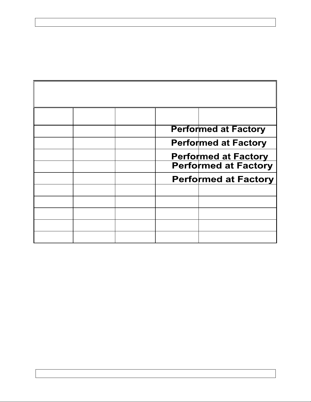
AMENDMENT RECORD
Amendment
Number
Amendment
Date
Section(s)
Changed
Date
Entered
Entered By
1 Apr 19/04 2
2 Aug 19/04 2
3 Nov 22/04 2
4 Jun 10/05 1,3
5 Jan 14/08 2
6 Mar 30/10 2
Insert any Amendment Instruction sheets after this page.
Performed at factory

SM41 Rev. 4.00 NPX138 Panel Mount Radio Manual
Nov 10, 2003 Page v
ENG-FORM: 820-0109.DOT
CONFIDENTIAL AND PROPRIETARY TO NORTHERN AIRBORNE TECHNOLOGY LTD.
3.4.2 RX/TX Status Indicator 3-3
3.4.3 Scan/Guard TX Switch 3-4
3.4.4 Guard Controls 3-4
3.5 General Controls — Normal Operating Mode 3-5
3.5.1 Channel Switch 3-5
3.5.2 Brightness Switch 3-5
3.5.3 Squelch Pushbutton 3-6
3.6 Channel Display 3-6
3.6.1 ID Display Line 3-6
3.6.2 RX Display Line 3-7
3.6.3 TX Display Line 3-7
3.7 Channel Editing 3-8
3.7.1 SELECT Switch 3-9
3.7.2 NEXT Switch 3-9
3.7.3 EDIT Switch 3-10
3.7.4 HELP Switch 3-10
3.8 Status Editing 3-10
3.8.1 NEXT and SELECT Switch Use 3-11
3.8.2 Status Edit Features 3-11
3.9 Tones 3-12
3.9.1 General 3-12
3.9.2 Tone Display and Selection 3-13
3.9.3 Turning Tones On and Off 3-15
3.10 Scanning 3-15
3.10.1 General 3-15
3.10.2 Scan Operation 3-16
3.10.3 Scan Modes 3-16
3.11 Wideband/Narrowband Operation 3-18
3.11.1 Editing Wideband/Narrowband Flag 3-18
3.12 Configuration Mode 3-18
3.12.1 Using Configuration Mode 3-18
3.12.2 Configuration Option Table 3-19

INSTALL_OPS
MANUAL AMENDMENT
Manual: SM41_NPX138 Amendment No.: 6
Document No. SM41\Install_Ops\809-0006 Amendment Date: Mar 30, 2010
Amendment No. 6 Mar 30, 2010 Page 1
ENG-FORM: 809-0109.DOT
CONFIDENTIAL AND PROPRIETARY TO NORTHERN AIRBORNE TECHNOLOGY LTD.
The purpose of this amendment is to add the current revision of the Mechanical
Installation drawing.
Amendment Instructions:
1 Remove Pages Replace With Pages
Title Page Title Page
2-5 Rev 4.00 Amendment 22-5 Rev 4.00 Amendment 3
2 Remove Drawing (Section 2) Add Drawing (Section 2)
NPX138\922-0 Rev 1.20 NPX138\922-0 Rev 1.21
Note: Ensure that all drawings are inserted in the order shown on the latest drawing lists.
3 Update the Amendment Record sheet at the front of the manual.
4 Insert this page into the manual after the Amendment Record sheet (page ii).
Manual Amendment ends after the following amended pages

INSTALL_OPS
MANUAL AMENDMENT
Manual: SM41 (NPX) Amendment #: 5
Document # SM41\Install_Ops\809-0005 Amendment Date: Jan 14, 2008
Amendment # 5 Jan 14, 2008 Page 1
ENG-FORM: 809-0109.DOT
CONFIDENTIAL AND PROPRIETARY TO NORTHERN AIRBORNE TECHNOLOGY LTD.
The purpose of this amendment is to update sections 2.3.4, 2.3.5 and 2.3.6.
Amendment Instructions:
1 Remove Pages Replace With Pages
2-1 and 2-2 Rev. 4.00 Amendment # 3 2-1 and 2-2 Rev. 4.00 Amendment # 5
2-3 and 2-4 Rev. 4.00 2-3 and 2-4 Rev. 4.00 Amendment # 5
2 Update the Amendment Record sheet at the front of the manual.
3 Insert this page into the manual after the Amendment Record sheet (page iii).
Manual Amendment ends after the following amended pages
INSTALL_OPS
MANUAL AMENDMENT
Manual: SM41 (NPX) Amendment #: 4
Document # SM41\Install_Ops\809-0004 Amendment Date: Jun 10, 2005
Amendment # 4 Jun 10, 2005 Page 1
ENG-FORM: 809-0109.DOT
CONFIDENTIAL AND PROPRIETARY TO NORTHERN AIRBORNE TECHNOLOGY LTD.
The purpose of this amendment is to add information relevant to the NPX138N-070.
Amendment Instructions:
1 Remove Pages Replace With Pages
1-5 Rev 4.00 1-5 Rev 4.00 Amendment # 4
3-3 and 3-4 Rev 4.00 3-3 and 3-4 Rev 4.00 Amendment # 4
3-7 and 3-8 Rev 4.00 3-7 and 3-8 Rev 4.00 Amendment # 4
3-11 and 3-12 Rev 4.00 3-11 and 3-12 Rev 4.00 Amendment # 4
3-19 Rev 4.00 3-19 Rev 4.00 Amendment # 4
2 Update the Amendment Record sheet at the front of the manual.
3 Insert this page into the manual after the Amendment Record sheet (page ii).
Manual Amendment ends after the following amended pages
INSTALL_OPS
MANUAL AMENDMENT
Manual: SM41 NPX138 Amendment #: 3
Document # SM41\Install_Ops\809-0003 Amendment Date: Nov 22, 2004
Amendment # 3 Nov 22, 2004 Page 1
ENG-FORM: 809-0107.DOT
PROPRIETARY AND CONFIDENTIAL TO NORTHERN AIRBORNE TECHNOLOGY LTD.
The purpose of this amendment is to amend the cable and wiring specifications in line
with Transport Canada requirements.
Amendment Instructions:
Remove Pages Replace With Pages
1
2-1 and 2-2 Rev 4.00 2-1 and 2-2 Rev 4.00 Amendment #3
2 Update the Amendment Record sheet at the front of the manual.
3 Insert this page into the manual after the Amendment Record sheet (page ii).
Manual Amendment ends after the following amended pages

INSTALL_OPS
MANUAL AMENDMENT
Manual: SM41 NPX138 Amendment #: 2
Document # SM41\Install_Ops\809-0002 Amendment Date: Aug 19, 2004
Amendment #2 Aug 19, 2004 Page 1
ENG-FORM: 809-0107.DOT
PROPRIETARY AND CONFIDENTIAL TO NORTHERN AIRBORNE TECHNOLOGY LTD.
The purpose of this amendment is to update the faceplate drawing.
Amendment Instructions:
Remove Pages Replace With Pages
1
2-5 2-5 Amendment #2
Remove Drawings (Section 2) Replace or add Drawings (Section 2)
2
NPX138\905-0 rev 1.40 NPX138\905-0 rev 1.50
Note: Ensure that all drawings are inserted in the order shown on the latest drawing lists.
3 Update the Amendment Record sheet at the front of the manual.
4 Insert this page into the manual after the Amendment Record sheet (page ii).
Manual Amendment ends after the following amended pages
MANUAL AMENDMENT
Manual: SM41 NPX138 Amendment #: 1
Document # SM41\Install_Ops\809-0001 Amendment Date: Apr 19, 2004
Amendment #1 Apr 19, 2004 Page 1
ENG-FORM: 809-0107.DOT
PROPRIETARY AND CONFIDENTIAL TO NORTHERN AIRBORNE TECHNOLOGY LTD.
The purpose of this amendment is to include the new revision of the NPX138\634-0 in
the manual.
Amendment Instructions:
1 Remove Page Replace With Page
2-5 rev 4.00 2-5 rev 4.00 Amendment #1
2 Remove Drawings (Section 2) Replace or add Drawings (Section 2)
NPX138\634-0 rev 1.00 NPX138\634-0 rev 1.10
Note: Ensure that all drawings are inserted in the order shown on the latest drawing lists.
3 Update the Amendment Record sheet at the front of the manual.
4 Insert this page into the manual after the Amendment Record sheet (page ii).
Manual Amendment ends after the following amended pages

SM41 Rev. 4.00 NPX138 Panel Mount Radio Manual
Nov 10, 2003 Page iv
ENG-FORM: 820-0109.DOT
CONFIDENTIAL AND PROPRIETARY TO NORTHERN AIRBORNE TECHNOLOGY LTD.
Table of Contents
Section Title Page
1.0 Description
1.1 Introduction 1-1
1.2 Purpose of Equipment 1-1
1.3 Features 1-1
1.4 Specifications 1-2
1.4.1 Electrical Specifications 1-2
1.4.2 Receiver 1-2
1.4.3 Transmitter 1-3
1.4.4 Physical Specifications 1-3
1.4.5 Environmental Specifications 1-4
1.5 Unit Nomenclature 1-4
1.5.1 Narrowband Capability 1-4
1.5.2 Options 1-4
1.5.3 Special Options 1-5
1.5.4 Voice Inversion Encryption 1-5
2.0 Installation
2.1 Introduction 2-1
2.2 Unpacking and Inspection 2-1
2.3 Installation Procedures 2-1
2.3.1 Warnings 2-1
2.3.2 Cautions 2-1
2.3.3 Notes 2-2
2.3.4 Cabling and Wiring 2-2
2.3.5 Antennas 2-3
2.3.6 Mechanical Mounting 2-4
2.3.7 Post-Installation Checks 2-4
2.3.8 Post Installation EMI Test 2-5
3.0 Operation
3.1 Introduction 3-1
3.2 Initial Operation 3-1
3.2.1 Power-up Help 3-1
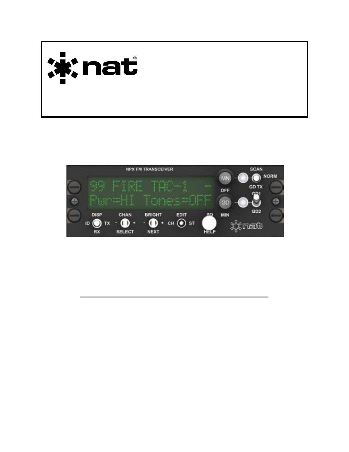
3.2.2 Initial Operating Display 3-2
3.3 Display 3-2
3.4 Function Controls 3-3
3.4.1 Main RX (Receive) Volume Control 3-3

SM41 Rev. 4.00 NPX138 Panel Mount Radio Manual
Nov 10, 2003 Page v
ENG-FORM: 820-0109.DOT
CONFIDENTIAL AND PROPRIETARY TO NORTHERN AIRBORNE TECHNOLOGY LTD.
3.4.2 RX/TX Status Indicator 3-3
3.4.3 Scan/Guard TX Switch 3-4
3.4.4 Guard Controls 3-4
3.5 General Controls — Normal Operating Mode 3-5
3.5.1 Channel Switch 3-5
3.5.2 Brightness Switch 3-5
3.5.3 Squelch Pushbutton 3-6
3.6 Channel Display 3-6
3.6.1 ID Display Line 3-6
3.6.2 RX Display Line 3-7
3.6.3 TX Display Line 3-7
3.7 Channel Editing 3-8
3.7.1 SELECT Switch 3-9
3.7.2 NEXT Switch 3-9
3.7.3 EDIT Switch 3-10
3.7.4 HELP Switch 3-10
3.8 Status Editing 3-10
3.8.1 NEXT and SELECT Switch Use 3-11
3.8.2 Status Edit Features 3-11
3.9 Tones 3-12
3.9.1 General 3-12
3.9.2 Tone Display and Selection 3-13
3.9.3 Turning Tones On and Off 3-15
3.10 Scanning 3-15
3.10.1 General 3-15
3.10.2 Scan Operation 3-16
3.10.3 Scan Modes 3-16
3.11 Wideband/Narrowband Operation 3-18
3.11.1 Editing Wideband/Narrowband Flag 3-18
3.12 Configuration Mode 3-18
3.12.1 Using Configuration Mode 3-18
3.12.2 Configuration Option Table 3-19

SM41 Rev. 4.00 NPX138 Panel Mount Radio Manual
Section 1.0 Description
1.1 Introduction
This manual contains description, installation, operation and maintenance information
on the NPX138 series of panel mount FM transceivers, serial numbers 1238 and
subsequent.
The NPX138 incorporates NAT’s proven user-friendly operating system with on-line
help, making it easy to program and use. The small size makes this radio ideal for
airframes where size and weight are a factor.
1.2 Purpose of Equipment
The NPX138 panel mount FM transceiver is a stand-alone radio designed for the single
mission user. It provides all the features needed to satisfy FM communications within
the VHF-FM high band.
1.3 Features
The NPX138 covers a frequency range of 138.000 MHz to 173.995 MHz in 5.0/6.25
kHz increments. Each of the 100 available channels can include a receive frequency
and CTCSS tone, transmit frequency and CTCSS tone, and an alpha/numeric
identifier.
A SCAN function allows scanning of selected channels. Transmit power of either 1 watt
or 10 watts is selectable from the front of the NPX138. Simplex and semi-duplex
operations are available. An optional guard receiver is available with some models.
DTMF encoding and direct keyboard entry can be effected by the use of the DTE12, an
accessory available from NAT.
Conveniently located beside the display are separate main volume, guard volume and
transmit select switches. Easily identified along the bottom of the front panel are
squelch test, channel up/down and display brightness controls. The aircraft dimmer
buss provides control for the panel lighting.
Depending on model selected the NPX138 can provide wideband (± 5.0 kHz Rated
System Deviation) and/or narrowband (± 2.5 kHz Rated System Deviation) by channel.
Compensation circuitry ensures that the average receive audio level remains constant
when the mode changes.
Nov 10, 2003 Page 1-1
ENG-FORM: 800-0106.DOT
CONFIDENTIAL AND PROPRIETARY TO NORTHERN AIRBORNE TECHNOLOGY LTD.

NPX138 Panel Mount Radio Manual SM41 Rev. 4.00
1.4 Specifications
1.4.1 Electrical Specifications
Input power 28 Vdc nominal
Current consumption 0.5 A receive/2.0 A transmit (typical)
0.8 A receive/3.0 A transmit (max.)
Panel lighting 28 Vdc, 14 Vdc or 5 Vdc dependent on model.
Sidetone output 25 mW @ 600 Ω, adjustable.
Microphone Amplified Dynamic or equivalent, 150 Ω
balanced/unbalanced
Frequency range 138.000 MHz to 173.995 MHz
Tone capability 38 standard CTCSS tones
Operating mode simplex or semi-duplex
1.4.2 Receiver
Channel increments 5 kHz/6.25 kHz
Audio output 100 mW @ 600 ΩBal/Unbal
Sensitivity
Main 0.5 µV max. @ 12 dB SINAD
Guard 0.5 µV max. @ 12 dB SINAD
Spurious response rejection 70 dB
Adjacent channel rejection
NPX138 (all models) 70 dB min. @ ± 25 kHz
NPX138N (all models)
Wideband 70 dB min. @ ± 25 kHz
Narrowband 60 dB min. @ ± 12.5 kHz
Intermodulation rejection 70 dB
Hum and Noise ratio
Unsquelched > 50 dB
Squelched < -80 dBw
Distortion < 4% @ rated output
Page 1-2 Nov 10, 2003
ENG-FORM: 800-0106.DOT
CONFIDENTIAL AND PROPRIETARY TO NORTHERN AIRBORNE TECHNOLOGY LTD.

SM41 Rev. 4.00 NPX138 Panel Mount Radio Manual
1.4.3 Transmitter
RF power output 1 W/10 W Selectable
RF input/output impedance 50 Ωnominal
Rated System Deviation
NPX138 (all models) ± 5.0 kHz max, limited
NPX138N (all models)
Wideband ± 5.0 kHz max, limited
Narrowband ± 2.5 kHz max, limited
Microphone Audio Sensitivity 100 mVrms into 150 Ω for 60% of rated system
deviation
Conducted spurious emissions
High power -64 dBc
Low power -55 dBc
Carrier frequency stability ±0.0003 %
FM hum and noise ratio >40 dB
AM hum and noise ratio >35 dB
Distortion <4 %
1.4.4 Physical Specifications
Height 1.88 inches (47.7 mm)
Overall depth 8.64 inches (219.5 mm)
Depth behind panel 7.66 inches (194.6 mm)
Width 5.75 inches (146.1 mm)
Weight 3.0 lbs. (1.4 kg)
Mounting Std. Dzus mounting (4 fasteners)
Connector type 25 pin D-subminiature male (pins)
Antenna connector BNC female
Nov 10, 2003 Page 1-3
ENG-FORM: 800-0106.DOT
CONFIDENTIAL AND PROPRIETARY TO NORTHERN AIRBORNE TECHNOLOGY LTD.

NPX138 Panel Mount Radio Manual SM41 Rev. 4.00
1.4.5 Environmental Specifications
Operating temperature -30 C to +60 C
Altitude 25,000 feet
Humidity 95%
Vibration DO-160C, Cat. M
1.5 Unit Nomenclature
Variants of the NPX138 series radios are identified as follows:
NPX138 N - 000
Narrowband Capability
Special Options
Lighting Power Encryption
1.5.1 Narrowband Capability
If the unit under consideration has the letter N after the NPX138 designation, it has the
capability for narrowband selection in addition to wideband. If this part of the name is
blank, the unit has wideband capabilities only.
NPX138 N- 000
N = Wideband and Narrowband modulation
Blank = Wideband modulation only
1.5.2 Lighting Power
The digit in the first position of the unit suffix indicates the lighting power used.
NPX138 N - 000
0 =28 Vdc Lighting
1 = 14 Vdc Lighting
2 = 28 Vdc NVG NVIS A Compliant
5 = 5 Vdc Lighting
7 = 28 Vdc NVG Compatible Lighting
8 = 14 Vdc NVG Compatible Lighting
9 = 5 Vdc NVG Compatible Lighting
Page 1-4 Nov 10, 2003
ENG-FORM: 800-0106.DOT
CONFIDENTIAL AND PROPRIETARY TO NORTHERN AIRBORNE TECHNOLOGY LTD.

SM41 Rev. 4.00 NPX138 Panel Mount Radio Manual
1.5.3 Special Options
The digit in the second position of the unit suffix indicates any special options installed.
NPX138 N - 000
0 =No Special options installed
5 = USFS Standard Guard
6 = Custom Guard - consult factory for details
7 = Synthesized Guard
Other = Special options installed - consult factory for details
1.5.4 Voice-Inversion Encryption
The digit in the third position of the unit suffix indicates whether voice inversion
encryption is installed.
NPX138 N - 000
0 =No Encryption
1 = Encryption
End of section 1.0
Nov 10, 2003 Page 1-5
ENG-FORM: 800-0106.DOT Amendment # 4 Jun 10, 2005
CONFIDENTIAL AND PROPRIETARY TO NORTHERN AIRBORNE TECHNOLOGY LTD.

SM41 Rev. 4.00 NPX138 Panel Mount Radio Manual
Section 2.0 Installation
2.1 Introduction
Information in this section consists of: unpacking and inspection procedures, installation
procedures, post-installation checks, and installation drawings.
2.2 Unpacking and Inspection
Unpack the equipment carefully, and locate the warranty card. Inspect the unit visually
for damage due to shipping and report all such claims immediately to the carrier
involved. Note that each unit should have the following:
- NPX138 Radio
- Warranty Card
- Operator’s Manual
- Release certification
Verify that all items are present before proceeding, and report any shortage immediately
to your supplier.
Complete the warranty card information, and send it to NAT when the installation is
complete. If you fail to complete the warranty card, the warranty will be activated on
date of shipment from NAT.
2.3 Installation Procedures
2.3.1 Warnings ←IMPORTANT!
Do not bundle any lines from this unit with transmitter coax lines. Do not bundle any
logic, audio, or DC power lines from this unit with 400 Hz synchro wiring or AC power
lines. Do not position this unit next to any device with a strong alternating magnetic
field such as an inverter or significant interference to operation will result. In all
installations, use shielded cable exactly as shown and ground as indicated.
Significant problems may result if these guidelines are not followed.
2.3.2 Cautions
All audio installations can be severely degraded by incorrect wiring and shielding, and
may result in much higher cross-talk, hum, and ground-loop interference. This should
be considered when audio wiring to and from the radio installation is performed.
Nov 10, 2003 Page 2-1
ENG-FORM: 805-0104.DOT Amendment # 5 Jan 14, 2008
PROPRIETARY AND CONFIDENTIAL TO NORTHERN AIRBORNE TECHNOLOGY LTD.

NPX138 Panel Mount Radio Manual SM41 Rev. 4.00
2.3.3 Notes
The case of the NPX138 must be electrically grounded for maximum resistance to low
frequency interference. A pin on the connector (Chassis ground) is provided and must
be connected by a short wire to a clean ground, not jumpered to the power ground wire
connection.
Refer to the aircraft structural repair manual and maintenance manual for instructions
and information pertinent to this installation.
2.3.4 Cable and Wiring
All unshielded wire shall be selected in accordance with the original aircraft
manufacturer’s maintenance instructions or AC43.13-1B Change 1, Paragraphs 11-76
through 11-78. Wire types should be to MIL-W-22759 as specified in AC43.13-1B
Change 1, Paragraphs 11-85, 11-86, and listed in Table 11-11. For shielded wire
applications, use Tefzel MIL-C-27500 shielded wire with solder sleeves (for shield
terminations) to make the most compact and easily terminated interconnect. Follow the
wiring diagrams in Section 2.5 as required.
Allow 3 inches from the end of the wire to the shield termination to allow the hood to be
easily installed. Note that the hood is installed after the wiring is complete.
Installation cabling must allow the NPX138 to be easily withdrawn for disconnection and
field service adjustments. Ensure an adequate service loop in the routing of the cables.
It can be a serious issue if the unit is installed with the cables so short that the unit
cannot be removed without disassembly of the surrounding structures. At least 30 cm
(1 foot) of free cable is recommended.
All wiring should be 22 AWG minimum, except power and ground connections, which
must be 20 AWG or larger, as indicated on the installation drawings. Ensure that the
ground connection is clean and well secured. To prevent inadvertent system failure,
power to this system must be supplied from a separate breaker or fuse and not
connected to any other device. A 5 A fuse or breaker is recommended (28 Vdc).
Coaxial cable should be in accordance with MIL-C-17 unless otherwise specified. Do
not use coax with PVC insulation. Teflon dielectric cable is encouraged at or above VHF
frequencies or where cable runs exceed 8 feet. Note that at VHF frequencies, cable losses
due to long cable runs and tight bends may cut the ERP (Equivalent Radiated Power) to
less than 50% of spec.
To prevent RF interference between similar systems, it is recommended that VHF FM
coax runs be widely separated, or be made using triaxial cable, with the outer shield
bonded to the airframe at one end only (transceiver end).
In communication intensive applications, poor cable routing and shielding may
drastically compromise over-all system performance. Symptoms may be spurious
squelch opening, RFI (Radio-Frequency Interference), and garbled reception.
Page 2-2 Nov 10, 2003
ENG-FORM: 805-0104.DOT Amendment # 5 Jan 14, 2008
PROPRIETARY AND CONFIDENTIAL TO NORTHERN AIRBORNE TECHNOLOGY LTD.

SM41 Rev. 4.00 NPX138 Panel Mount Radio Manual
RF cables must be neatly terminated (solder or crimp), and tested for shorts prior to
system check-out (not while connected to the radio or antenna). Keep cable bends to a
minimum at the antenna. Avoid sharp bends in the coax cables (minimum 3" radius) to
prevent severe reflections. If sharp bends are required, use 90°elbow adapters.
Fabrication & installation of wiring harness should be in accordance with the original
aircraft manufacturer’s maintenance instructions or AC 43.13-1B Change 1, chapter 11,
sections 5 to 13, 16 and 17.
Grounding and bonding should be in accordance with the original aircraft manufacturer’s
maintenance instructions or AC 43.13-1B Change 1, chapter 11, section 15.
2.3.5 Antennas
Correct antenna placement and mounting is critical in order to achieve the best possible
performance. In general, keep all antennas as widely separated as possible and clear
of any large airframe obstructions.
Installation of the antenna should be in accordance with the original aircraft
manufacturer’s instructions for continued airworthiness or AC 43.13-1B Change 1,
chapter 11, section 15 and AC 43.13-2A chapter 3. If possible, the antenna should be
located a minimum of 12 ft from aircraft navigation receiver antennas and a minimum of
4 feet from aircraft communications and ELT antennas. Be careful not to choose
separations that closely approximate ¼, ½ or whole-number multiples of the navigation
or communications system wavelength.
Note: Avoid any placement that puts antennas of like frequencies close together.
Bottom mounted antennas will perform best in flight, but poorest on the ground during
testing. Antennas may be severely degraded by 'masking' effects of the fuselage or
stabilizers, and generally give best performance when bottom mounted.
To reduce interference from rotor modulation and other undesirable stimuli, any blade or
whip antenna must be surrounded by a ground plane surface (metallic, grounded
material) with a radius equal to or greater than the height of the antenna. Under the
same conditions, the antenna is also much less likely to cause interference to other
aircraft systems (e.g. coupling into audio system, fluctuations in instrumentation, etc.).
Poor grounding will result in severe reflected power and high levels of RFI throughout
the airframe.
Avoid antenna locations that will become fouled with oil, water, fuel or dirt, as this will
degrade performance. Roof mounts (in close proximity to rotor blades) are permissible.
Nov 10, 2003 Page 2-3
ENG-FORM: 805-0104.DOT Amendment # 5 Jan 14, 2008
PROPRIETARY AND CONFIDENTIAL TO NORTHERN AIRBORNE TECHNOLOGY LTD.
This manual suits for next models
1
Table of contents


