Northern Design multicube User manual

Pulse Output Module
Page - 1 -
multicube
Modular Metering System
Pulse Output Module Operating Manual
Revision 2
Published October 2014
© Northern Design Metering Solutions

Pulse Output Module
Page - 2 -
1 Pulse Output Module
1.1 Description
The multicube pulse output module is a 12 channel relay board with one side of each relay
connected to a common terminal. The module connects as one or more of up to ten
option modules to the right hand side of the multicube main display. Each of the 12
channels can be configured to act as either a pulse output responding to changes in
accumulating energy registers or as an alarm output responding to level changes of
instantaneous registers.
The pulse output module has a Modbus ID determined by the ID of the main display unit and
the position the unit is placed in the option modules. One pulse module replaces one meter
module or two metering units. The Modbus tables described later are accessed on this ID.
Multiple pulse modules can be connected to the multicube with corresponding reduction of
the maximum number of meter modules.
2 Safety
This manual gives details of safe installation of pulse output modules for connection to the
multicube electricity metering systems. Safety may be impaired if the instructions are not
followed or the system is used in a manner not specified by the manufacturer. Labels give
details of equipment ratings for safe operation. Take time to examine all labels before
commencing installation. Safety symbols on the meter have specific meanings.
Caution Risk of Danger
Refer to Instructions
Danger
Risk of Electric Shock
Safety may be impaired if the instructions are not followed or the module or
metering system is used in a manner not specified by the manufacturer.
Contains no user serviceable parts. Field wiring and commissioning should only be
carried out by qualified personnel, in compliance with applicable national
regulations.
e.g. National Electrical Code (NEC) for US; Canadian Electrical Code for Canada
For further Information contact the manufacturer:
Address: Northern Design (Electronics) Ltd: 228 Bolton Road, Brad ord, West Yorkshire, BD3 0QW. (UK)
Web: http://www.ndmeter.co.uk
2.1 Maintenance
The equipment should be maintained in good working order. Damaged equipment must be
returned to the manufacturer (or his authorized agent) for repair. The meter may be cleaned
by wiping lightly with a soft cloth. No solvents or cleaning agents should be used. All inputs
and supplies must be isolated before cleaning any part of the equipment.

multicube
Modular Metering Pulse Output Module
Pulse Output Module
Page - 3 -
2.2 Installation
For details for attaching modules to the multicube refer to the multicube Modular
Metering system Installation Guide.
2.3 Schematics
2.4 Terminal Connections
The pulse module terminal connector shall only be connected to low voltage (SELV) circuits.
The maximum operating voltage for the relays is 100V ac/dc and the maximum operating
current for the relays is 100mA ac/dc.
Terminal Connector (supplied): 300Vac, 11A, 110 DegC; Tightening Torque < 0.25Nm.
Cables running within the electrical enclosure may come close to high voltages and therefore
must be insulated to the following minimum specification:
Cables: UL 1015, 105 DegC , 600Vac. 30-14 AWG.

multicube
Modular Metering Pulse Output Module
Pulse Output Module
Page - 4 -
2.5 Accessing Module Wiring Terminals
Module wiring terminals are protected by terminal covers. The terminal covers are designed
to slide towards the front of the module and are captive so they may not be removed and
misplaced.
To access the terminals:
1. Push down the lower terminal cover release clip using a tool.
2. Slide the terminal cover forward to its full extent
3. Flip the terminal cover up to sit in front of the module while accessing the wiring
terminals.
OTE: The release clip may be covered with a tamper evident label (20mm x 18mm) to detect
unauthorized access.
Beneath the sliding cover on the bottom of the module is a 13-way terminal connector. The
terminal nearest the front of the unit is common to each of the 12 configurable relay channels.
These relays connect to the rest of the terminals with channel 1 connected to the rearmost
terminal and channel 12 connected to the terminal nearest to the common.
multicube
Modular Metering Pulse Output Module
Pulse Output Module
Page - 5 -
2.6 System Information Pages
The system information page provides the user with details of the connected modules at any
time during operation of the multicube system. Information about the settings of any
connected Pulse Output Module can be found here.
The boxes represent the position each module is connected to the main display unit and the
elements in each module. The meter modules have two meters per module and are indicated
by an upper and lower box, while a pulse module is only indicated by a single upper box.
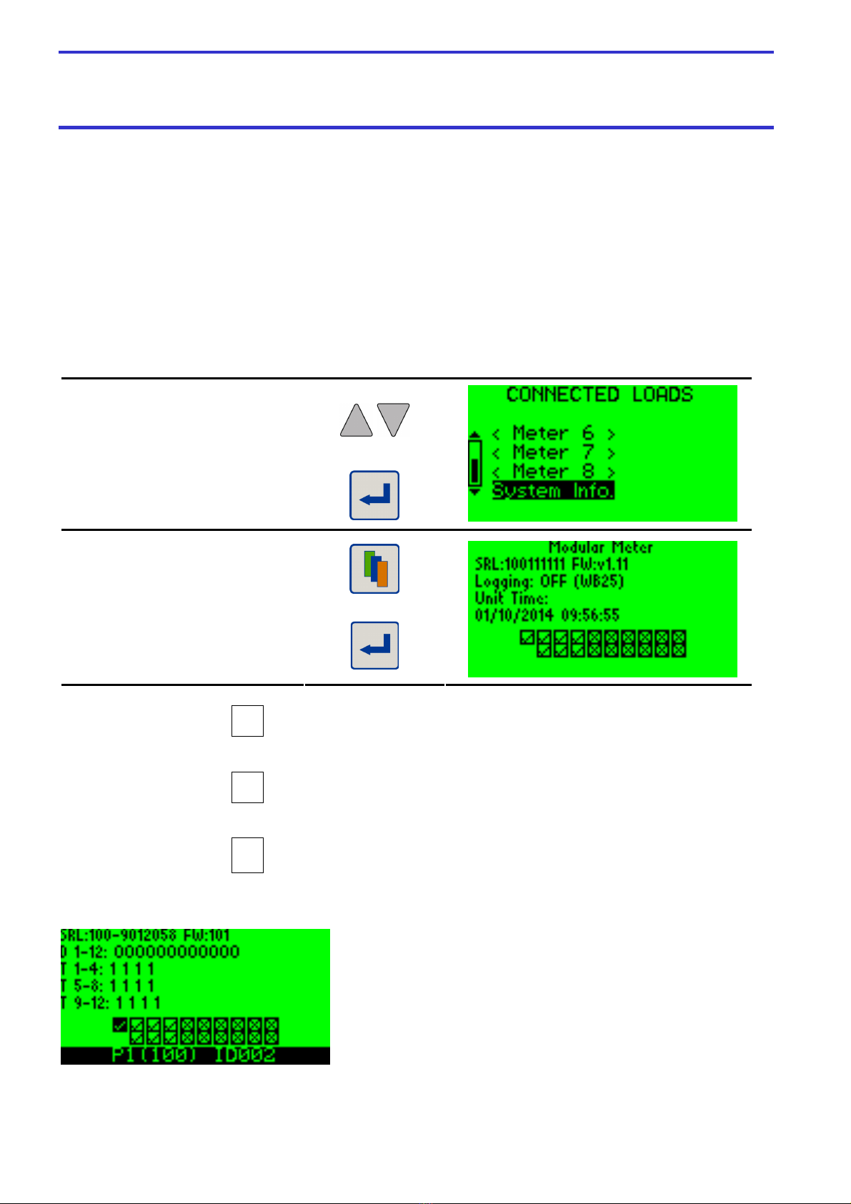
2.6.1 Accessing Pulse Module Information
Select System Info
From the
CONNECTED LOADS
View the
System Information page
Select to View
Main display /Module(s)
Information
Return to Module List
Module present and configured
Module not present
?
Module present but position does not match ID
Pulse Module Information
Selected Module: Serial Number Firmware Version
Channel Direction Setting: N/O = O, N/C = I (Output or Input)
Channel Pulse Duration Setting:
Channel Numbers & their Pulse Durations ( set duration = value
displayed in this page x 0.1 seconds), 0 if set to Alarm
Module Status – Selected Module Highlighted
Module Position (Type) Comms ID

multicube
Modular Metering Pulse Output Module
Pulse Output Module
Page - 6 -
3 Pulse Output Settings
3.1 Output Direction
Each channel can be set to act as a normally open (N/O) or as a normally closed (N/C)
contactor although without power all channels are open circuit as follows.
3.1.1 Output Direction Summary
Direction Output Function
0 N/O OFF = OPEN
ON = CLOSED
1 N/C OFF = CLOSED
ON = OPEN
3.1.2 Set the Output Direction
Enter Setup Mode Hold Setup Keys for 5 Seconds
Select Pulse Output
From the Main Menu
View/Edit the Pulse Output Setup
Select a Pulse Output Module
(in case of more than one pulse
output module connected)
Select a Pulse Output Channel
Select Normally Open/Closed

multicube
Modular Metering Pulse Output Module
Pulse Output Module
Page - 7 -
3.2 Associated Load ID
Any of the Modbus devices in a multicube system can be associated with an individual pulse
output. For example, it may be required to provide a pulse output associated with a selected
energy register measured by one of the metering modules. It is possible to set this value to
the Modbus ID of any chosen meter or, if set to alarm, to that of any other module or the Main
display unit.
To operate, each separate channel is required to be associated with a Modbus ID and a
parameter. The ID can be that of the main display or one of the metering unit option modules.
When the associated parameter is set to below the value 256, the channel is considered a
pulse output otherwise the channel is set as an alarm.
When an individual channel parameter is selected as a pulse output, the Modbus ID must be
associated with a corresponding meter for correct operation. When an alarm register is
selected the Modbus ID can also be that of the main display unit or another pulse output
module, but the Modbus register must be valid for the target unit selected.
For each of the output channels, in order to set the associated Modbus ID using the
multicube display and keypad, the meters detected on the multicube are presented as a
number of three phase and single phase loads for selection.
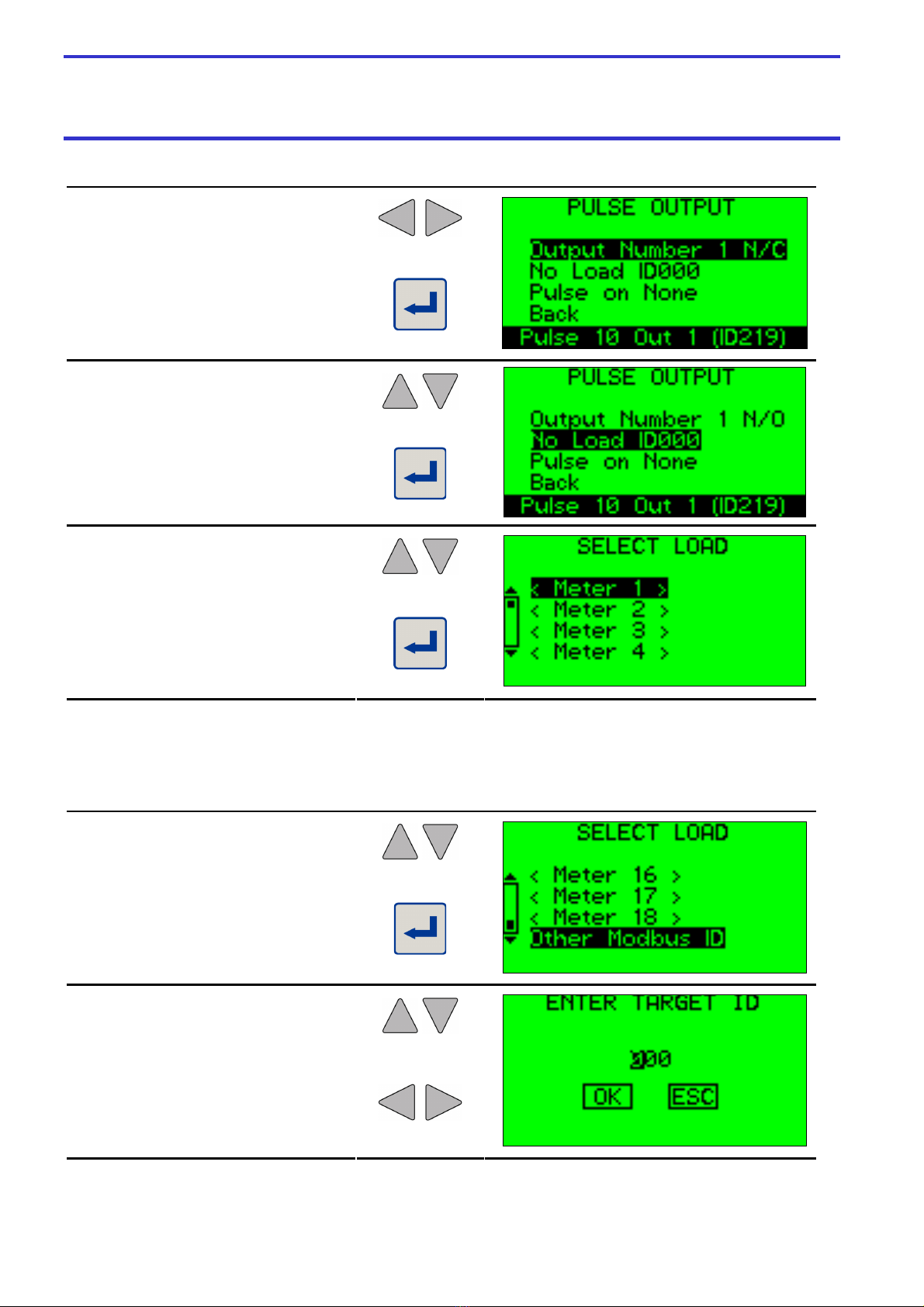
3.2.1 Set the Associated Load
Enter Setup Mode Hold Setup Keys for 5 Seconds
Select Pulse Output
From the Main Menu
View/Edit the Pulse Output Setup
Select a Pulse Output Module
(in case of more than one pulse
output module connected)
multicube
Modular Metering Pulse Output Module
Pulse Output Module
Page - 8 -
Select a Pulse Output Channel
Select Normally Open/Closed
Choose the Load Selection Option
Enter Load Selection Menu
Choose Load
Enter to Select Load
Alternatively, a Modbus ID may be entered manually if, for instance, a register on the main
display unit is required.
3.2.2 Set the Associated ID
Choose Manual ID Entry
Enter ID Input Menu
Edit Digit
Choose Digit or Button

multicube
Modular Metering Pulse Output Module
Pulse Output Module
Page - 9 -
Accept or Decline Value

multicube
Modular Metering Pulse Output Module
Pulse Output Module
Page - 10 -
3.3 Output Type
Each of the output channels can be set for a pulse output or an alarm.
3.3.1 Set the Output Type
Select Pulse/Alarm
Choose Pulse or Alarm
Enter Pulse or Alarm Settings
Menu

multicube
Modular Metering Pulse Output Module
Pulse Output Module
Page - 11 -
4 Pulse Output Settings
4.1 Associated Parameter
When this parameter is set to one of values in the table below, then the output behaves as a
pulse output which is associated with the corresponding energy register selected. Three
phase meters can select only the system energies, while single phase loads can only select
the energies on their corresponding channel.
For three phase meters export energies are available only if the auto-rotate setting has been
disabled. Some energies may not be available when functions such as dual source logging
are enabled and will be read as zero. Refer to the multicube modular meter Modbus Comms
manual for more information.
If the auto-rotate settings are changed or a meter is changed from a three phase to three
single phase loads or vice-versa, then any relays that refer to that meter will be reset on all
the installed pulse modules.
4.1.1 Pulse Parameter List
Associated
Parameter 3 Phase Energy Channel 1 Energy Channel 2 Energy Channel 3 Energy
0 No function assigned
(Output always OFF)
No function assigned
(Output always OFF)
No function assigned
(Output always OFF)
No function assigned
(Output always OFF)
1 System kWh
2 Channel 1 kWh
3 Channel 2 kWh
4 Channel 3 kWh
5 System kvarh
6 Channel 1 kvarh
7 Channel 2 kvarh
8 Channel 3 kvarh
9 System Export kWh*
10 System Export kvarh*
11 System kVAh
12-255 Unused Unused Unused Unused
* Only available when auto-rotate is off.
To select the appropriate parameter, enter the pulse settings menu by highlighting the ‘Pulse
On …’ selection and pressing the Enter key. The associated parameter should be highlighted
and can be selected to present the parameters listed in the above table. Choose the
appropriate parameter using the up and down keys and press the Enter key.

multicube
Modular Metering Pulse Output Module
Pulse Output Module
Page - 12 -
4.1.2 Selecting Associated Pulse Parameter
Choose Pulse
Enter Pulse Settings Menu
Choose Pulse Parameter Selection
Enter Associated Pulse Parameter
Selection Menu
Choose Appropriate Parameter
Select Associated Parameter
multicube
Modular Metering Pulse Output Module
Pulse Output Module
Page - 13 -
4.2 Pulse Rate
When an individual channel is set as a Pulse Output, this setting determines how many
increments of the associated energy register are required before each pulse is triggered. The
default value for this parameter is 1 and a single pulse occurs for each increment of the
associated energy register. If, for example, this parameter is set to 10 then the pulses will
occur only after each 10 increments of the associated energy register.
The value shown on the display is scaled and dimensioned according to the scale value
stored for the corresponding parameter. The actual value set will be an integer number
directly comparable with the reading obtained from the meters. When the target parameter
has increased by the pulse rate since the previous pulse a new pulse is triggered to be output
the next second. If the value has increased by a multiple of this value, a single pulse will be
output each second until a pulse has occurred for each increase of the pulse rate.
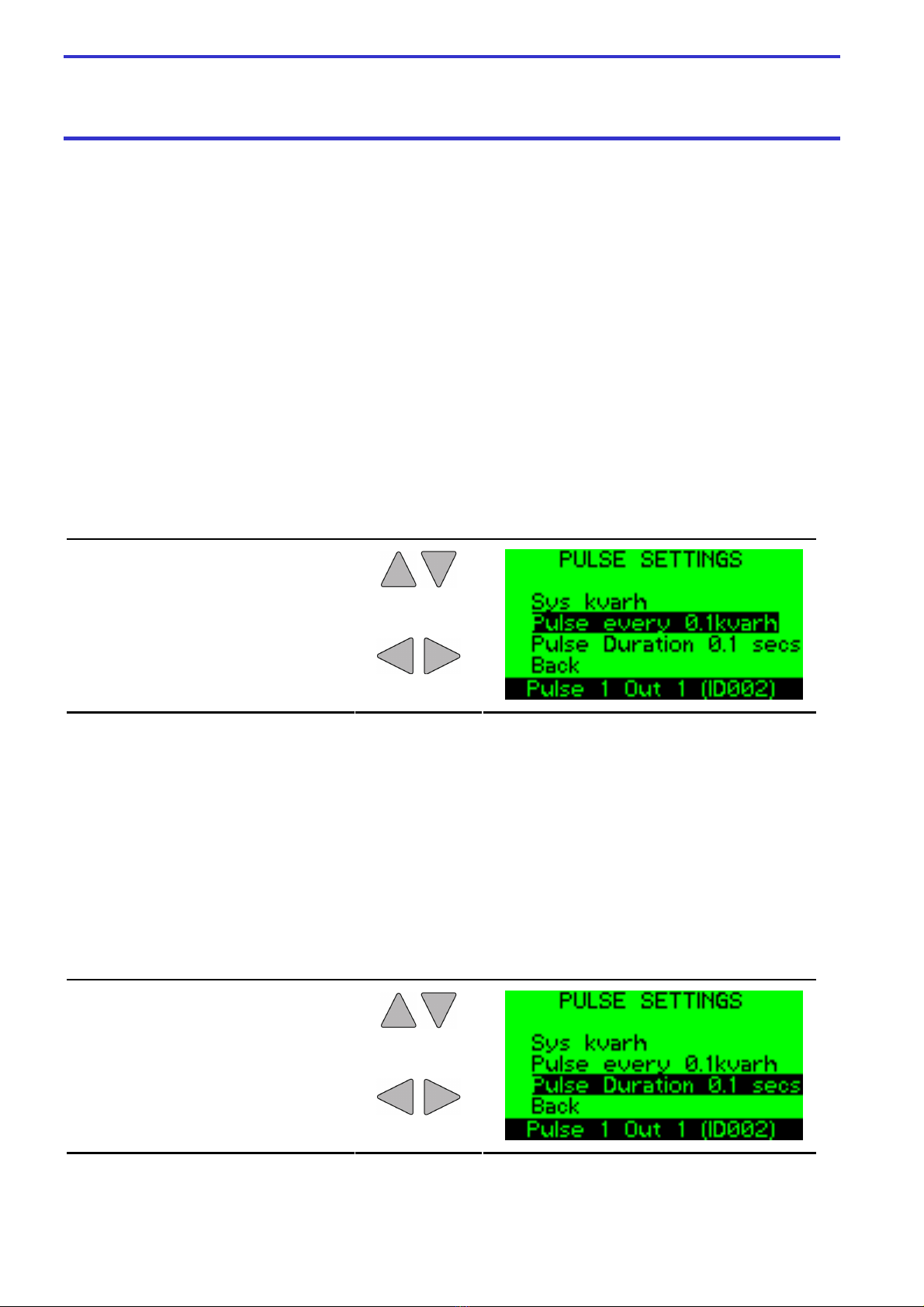
4.2.1 Adjusting Pulse Rate
Choose Pulse Rate
Adjust Pulse Rate
4.3 Pulse On Time
When an individual channel is set as a Pulse Output, this setting determines how long the
contacts will remain in the triggered condition after the pulse has occurred. This value is
scaled in 0.1S (e.g. 1 = 0.1S, 2=0.2S etc). The triggered condition may be active when the
relays are open then driven closed for this duration with a normally open output type, or
active when the relays are closed then driven open for this duration with a normally closed
output type.
4.3.1 Adjusting Pulse Duration
Choose Pulse Duration
Adjust Pulse Duration
multicube
Modular Metering Pulse Output Module
Pulse Output Module
Page - 14 -
5 Alarm Functionality
5.1 Use as Alarm Outputs
If the parameter value is greater than 255, then the output is set as an Alarm associated with
the register which would normally be read from the equivalent Modbus data address. This
parameter would normally be an instantaneous Modbus register such as system kW or phase
amps but any Modbus data address could be selected.
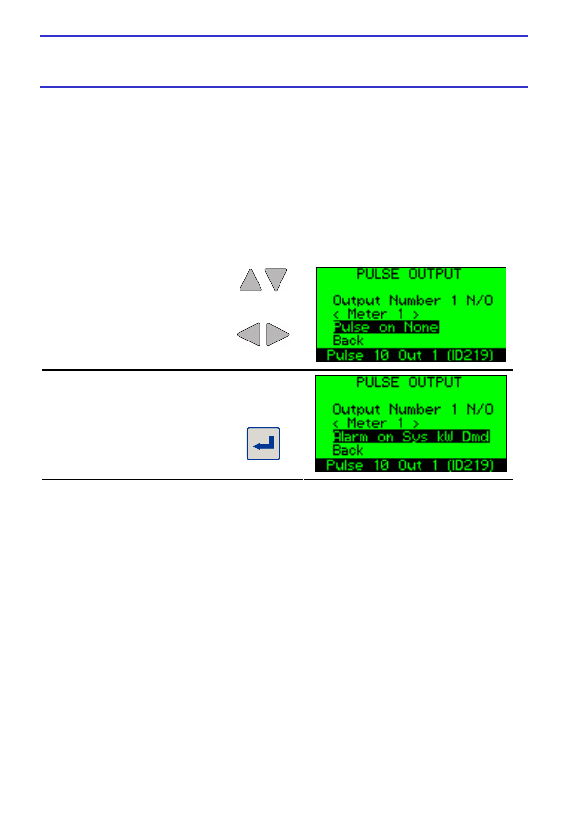
5.1.1 Selecting Alarm
Choose Pulse/Alarm
Select Alarm
Enter Alarm Menu
multicube
Modular Metering Pulse Output Module
Pulse Output Module
Page - 15 -
5.2 Alarm Register Parameter
Each Alarm is associated with a single Modbus register, which in turn is linked to a measured
parameter in the meter. From the Alarm Menu select the Alarm Parameter Selection Menu to
show a list from which to choose the desired parameter. The lists of parameters differ
between 3 phase loads and the phase a single phase load occupies.
5.2.1 3 Phase Alarm Parameter List
Associated 3
Phase Register Measured Value
7691
Phase 1 Volts
7692
Phase 2 Volts
7693
Phase 3 Volts
7694
Line Volts 1-2
7695
Line Volts 2-3
7696
Line Volts 3-1
7717
Phase 1 V Dmd
7718
Phase 2 V Dmd
7719
Phase 3 V Dmd
7688
Phase 1 Amps
7689
Phase 2 Amps
7690
Phase 3 Amps
7732
Neutral Amps
7714
Phase 1 Amps Demand
7715
Phase 2 Amps Demand
7716
Phase 3 Amps Demand
7705
System kW
7702
Phase 1 kW
7703
Phase 2 kW
7704
Phase 3 kW
7709 System kVA
7713
System kvar
7710
Phase 1 kvar
7711
Phase 2 kvar
7712
Phase 3 kvar
7701
System Power Factor
7698
Phase 1 Power Factor
7699
Phase 2 Power Factor
7700
Phase 3 Power Factor
7726 System kW Demand

multicube
Modular Metering Pulse Output Module
Pulse Output Module
Page - 16 -
5.2.2 Single Phase Alarm Parameter List
Channel 1
Register
Channel 2
Register
Channel 3
Register
Measured
Value
7966
7967 7968 Volts
7963
7964 7965 Amps
7954
7955 7956 kW
7957
7958 7959 kvar
7973
7974 7975 PF
7951
7952 7953 kW Dmd
5.2.3 Set Alarm Parameter
Choose Alarm Parameter
Enter Alarm Parameter Menu
Choose Alarm Parameter
Select Alarm Parameter
If the desired register is not in the list select Other Modbus Register and enter the register
address manually. Ensure the register is available on the unit with the associated Modbus ID.
5.2.4 Set Alternative Alarm Parameter
Choose Other Modbus Register
Enter Register Entry Menu

multicube
Modular Metering Pulse Output Module
Pulse Output Module
Page - 17 -
Edit Digit
Choose Digit or Button
Accept or Decline Value
If the desired register is not in the list, no specific phase will be attributed to the relay and so
only the Modbus ID will be shown for the load. The values shown for a register not in the
alarm parameter list will be without any scaling as it is read from the modbus register. Alarm
set points will have to be in the same unscaled format and the values selected accordingly.
5.2.5 No Load Identified For Alternative Alarm Parameter
No Phase Associated With
Register – Load Reverts To
Modbus ID

multicube
Modular Metering Pulse Output Module
Pulse Output Module
Page - 18 -
5.3 Alarm Levels
Each Alarm features High and/or Low settings with hysteresis. The levels can be in the range
-32768 to 32767 (signed 16 bit numbers), except for some of the registers selected from the
alarm parameter list that have known ranges. The high alarm trigger level must be above the
low alarm trigger level. The high alarm reset level must not be higher than the high alarm
trigger level and must be higher than the low alarm trigger level. The low alarm reset level
must not be lower than the low alarm trigger level and must be lower than the high alarm
trigger level.
5.3.1 Alarm Set Points
Set Delay – The consecutive period of time a High Set or Low Set point must be exceeded
before an alarm output is ON. Alarms are released on detecting a release condition with no
delay.
High Set Point – If the value in the selected Modbus register exceeds this value for a time
period greater than the Set Delay the alarm is set (switched ON).
High Release Point – If the alarm is ON and the value in the selected Modbus register is
lower than this value, for a single measurement period (1 second) the alarm is released
(switched OFF).
Low Set Point – If the value in the selected Modbus register is lower than this value for a
time period greater than the Set Delay the alarm is set (Switched ON).
Low Release Point – If the alarm is Set Low and the value in the selected Modbus register
exceeds this value, for a single measurement period (1 second) the alarm is released
(switched OFF).

multicube
Modular Metering Pulse Output Module
Pulse Output Module
Page - 19 -
The Alarm Level Menu shows an ordered list of the level settings and the current value of the
target parameter with values reducing from high to low. A bar at the side of the values shows
the relative relationships between the settings. The areas above the high trigger level and
below the low trigger setting are in black. The areas between the trigger levels and their
respective reset points are shaded. If the reset points overlap, darker shading is employed.
The current value of the target register is indicated by an arrow.
The scaling of the register value is the same as that provided over the Modbus link. A phase
voltage display of 240.0 and a scale value of 2, for example would be represented by a
Modbus register value of 2400. If the associated register is not recognised as one of the
parameters in the lists then no scaling is performed.
5.3.2 Set Alarm Levels
Choose Alarm Levels
Enter Alarm Levels Menu
Choose Level of Alarm
Edit Alarm Level
Choose Back
Accept Values & Exit Menu
ote: The values shown are for illustrative purposes only and do not reflect those obtained from a real system.

multicube
Modular Metering Pulse Output Module
Pulse Output Module
Page - 20 -
5.4 Alarm Delay
An optional delay can be placed on an alarm condition to ensure it is valid for a set number of
seconds. The first occurrence of an alarm condition will initiate the delay count for the set
period. The alarm condition must be present for the complete duration of the delay period and
the alarm will then trigger at the end of that period. If the alarm condition reverts to not being
present, the delay count is reset and the alarm is not triggered.
5.4.1 Set Alarm Delay
Choose Alarm Delay
Edit Delay Period
Table of contents
Other Northern Design Measuring Instrument manuals

Northern Design
Northern Design MultiCube Series Instruction Manual

Northern Design
Northern Design MultiCube950mV User manual

Northern Design
Northern Design Cube400V User manual

Northern Design
Northern Design PowerRail300 User manual

Northern Design
Northern Design Rail350V-IP User manual

Northern Design
Northern Design Cube 400 User manual


