TUF-2000F User Manual
8
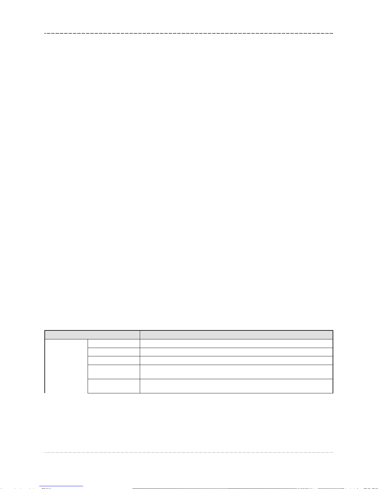
display is used as the display device.
M3.
Setup for local segmental LCD display. Enter 0 or 1 for the non-auto-scan mode;
Enter 2~39 for the auto-scan mode. In the auto-scan mode the display will
automatically scan displaying from 00 to the entered number of the local segmental
LCD display.
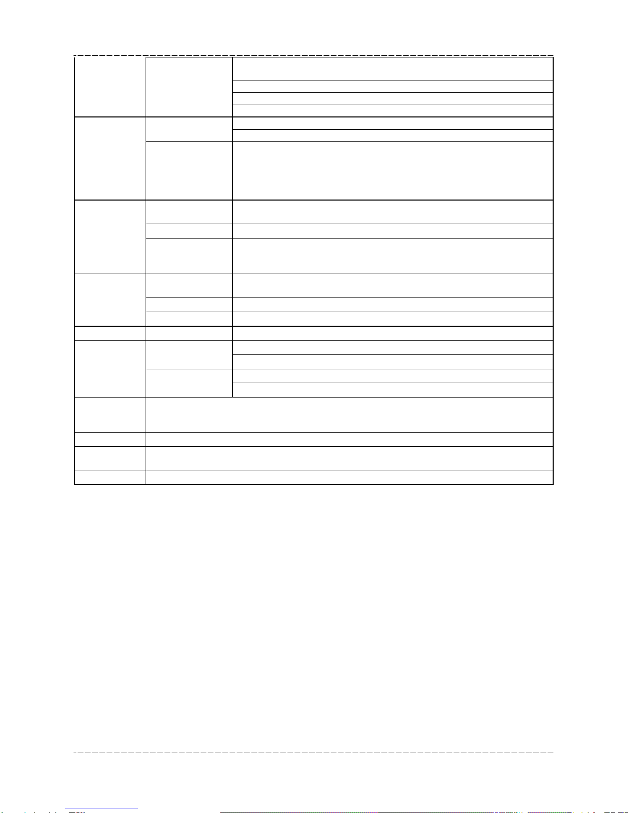
M40
Flow rate damper for a stable value. The damping parameter ranges form 0 to 999
seconds.
0 means there is no damping. Factory default is 10 seconds
M41 Low flow rate (or zero flow rate) cut-off to avoid invalid accumulation.
M42 Zero calibration/Zero point setup. Make sure the liquid in the pipe is not running
while doing the setup.
M43 Clear the zero point value, and restore the solidified zero point value.
M44 Set up a flow bias. Generally this value should be 0.
M45 Flow rate scale factor. The default value is ‘1’.
Keep this value as ‘1’, when no calibration has been made.
M46
Networks address identification number. Any integer can be entered except
13(0DH, carriage return), 10 (0AH, line feeding), 42 (2AH), 38, 65535.
Every set of the instrument in a network environment should have a unique IDN.
Please refer to the chapter for communication.
M47
System locker to avoid modification of the system parameters.
If password is forgotten, you could send a command ‘LOCK0’ to the serial input to
unlock. Or you can write 0 to REGISTER49-50 under MODBUS protocol.
M48
Entry to linearity correcting data inputs. By using of this function, the non-linearity of
flow meter will be corrected. Correcting data shall be obtained by careful
calibration.
M49 Displays the input contents for the serial port.
By checking the displays, you can know if the communication is ok.
M50
Switches for the built-in data logger. There are as many as 22 different items can
be chosen. To turn this function, select ‘YES’ the system will ask for selecting the
items. There are 22 items available. Turn on all those items you want to output
M51
Window to setup the time of scheduled output function (data logger, or
Thermo-printer). This includes start time, time interval and how many times of
output. When a number great than 8000 entered for the times of output, It means
the output will be keeping always. The minimum time interval is 1 second and the
maximum is 24 hours.
M52
Data logging direction control.
(1) If ‘Send to RS485’ is selected, all the data produced by the data logger will be
transmitted out through the RS-232/RS485 interface
(2) If ‘To the internal serial BUS is selected, the data will be transmitted to the
internal serial bus which allows a thermal printer, or a 4-20mA analog output
module, to be connected to it.
M53 Display analog inputs, AI5, current value and its corresponding temperature or
pressure or liquid level value.
M54 Pulse width setup for the OCT (OCT1) output. Minimum is 6 mS, maximum is 1000
mS
M55 Select analog output (4-20mA current loop, or CL) mode. Available options: