NORTHERN ELECTRIC BDM-300 WiFi Instruction Manual

BDM-300/400/600/800 WiFi
Installation User Manual
Northern Electric Power Co,. Ltd.
V2.0 rev.2023.3.12

DISCLAIMERS
The information in these documents is the property of Northern Electric Power Co., Ltd., hereafter
referred to as NEP.
No part of this document may be reproduced, stored in a retrieval system, or transmitted, in any form or
by any means, mechanical, electronic, photographic, magnetic or otherwise, without the prior written
permission of NEP. Internal reproduction used solely for the purpose of product evaluation or other
proper use is allowed and does not require prior approval.
NEP makes no representations or warranties, express or implied, with respect to this documentation or
any of the equipment and/or software it may describe, including without limiting the generality of the
foregoing, to any implied warranties of utility, merchantability, or fitness of any particular purpose. All
such representations or warranties are expressly disclaimed. Neither NEP nor its distributors or dealers
shall be liable for any indirect, incidental, or consequential damages under any circumstances.
The exclusion of implied warranties may not apply in all cases under some statutes, and thus the above
exclusion may not apply.
This document and the material furnished within is believed to be complete, accurate and up-to-date.
Readers are cautioned, however, that product improvements and field usage experience may cause NEP
to make changes to specifications and contents without prior notice, or per contract provisions in those
cases where a supply agreement requires advance notice. NEP assumes no responsibility for the use of
this material, and no responsibility for any damages, including indirect, incidental or consequential
damages, caused by reliance on the material presented, including, but not limited to, omissions,
typographical errors, arithmetical errors or listing errors in the content material.
Specifications and contents in these documents are continually reviewed, and subject to change without
prior notice where necessary. However, discrepancies cannot be excluded. No guarantee is made for the
completeness of these documents.
NEP WARRANTY
You can download the latest warranty terms and conditions from website at northernep.com.
For technical problems concerning NEP products and requiring assistance, please refer to CONTACT.
Trademarks
All trademarks, including company, brand products and service names, are recognized, even if not
explicitly identified as such. Missing designations do not mean that a product or brand is not a registered
trademark.
INFORMATION ON THIS DOCUMENT
Target Group
This document is intended for “Qualified Persons" and "End Users".
Tasks marked with a warning symbol and the caption “Qualified Persons” require associated skills to
avoid and deal with the dangers and risks in installing and using the product and tools described in this
document.
Tasks not marked do not require particular qualifications and skill sets, and therefore can be performed
by end users.
Qualified Persons
Qualified Persons required
**Qualified persons** are required to be familiar, understand and capable of following all applicable
regulations, directives and laws, and are aware of the potential risks to perform the activities marked in
this document.
The following knowledge and skills are required for qualified persons:
Knowledge of how an inverter works and is operated
Knowledge of all applicable standards and directives, including country-specific grid conditions and
regulatory guidelines
Knowledge and training of how to minimize and deal with dangers and risks associated with using,
installing, and repairing electrical devices and installations
Knowledge and training in the installation and commissioning of electrical devices, especially those
associated with PV systems
Knowledge and training of and compliance with this document and all safety information
Knowledge of warranty terms and conditions associated with the product described in this
document
"Qualified Person" means he/she is validly licensed from the local authority in:
Safely and properly installing electrical equipment and PV power systems
Safely and properly applying all applicable installation codes in practice
Properly analyzing and minimizing the hazards in performing electrical work and finished
works for all persons and properties involved

Properly selecting and using Personal Protective Equipment (PPE)
End Users
End users can be referred to any who intend to use the product described in these documents, and must
avoid performing tasks marked in this document with requirement for qualified persons.
End users should use this document for a comprehensive understanding of general features and
functions involved in the product, and as a guideline for performing tasks that do not require particular
qualifications independently.
DO NOT
put this product in use unless it has been successfully installed and commissioned by a
qualified person following described requirements and steps in the section of Installation and
Commissioning as well as all applicable laws and safety regulations.
Content and Structure
This document describes the unpacking, mounting, installation, commissioning, startup, operation,
troubleshooting, maintenance, as well as the disconnection of the produc. Applicable inverter models are
listed below:
BDM-300
BDM-400
BDM-600
BDM-800
This document, as well as any data, images and illustrations included herein, are reduced to the essential
information for the user’s guidance, and therefore deviate from the real product. Update of this
document may not be announced.
For the latest version of this document and further information on the described product, please visit
website at northernep.com.
For technical problems concerning the products in this document and requiring assistance, please refer
to CONTACT.
Copyright © 2021 Northern Electric Power Co,. Ltd.. All rights reserved.
Warning Messages
The following warning messages are used in this document, and should be familiarized before
installation or operation of the product.
Failure to follow may result in injury, damage to properties, or a fatal event.

DANGER
denotes a hazardous situation which, if not avoided, will result in death or severe injury.
WARNING
denotes a hazardous situation which, if not avoided, can result in death or severe or
moderate injury.
CAUTION
denotes a hazardous situation which, if not avoided, can result in moderate or minor
injury.
NOTICE
denotes a situation which, if not avoided, that can result in property damage

FCC COMPLIANCE
This equipment has been tested and found to comply with the limits for a Class B digital device, pursuant
to part 15 of the FCC Rules. These limits are designed to provide reasonable protection against harmful
interference in a residential installation. This equipment generates uses and can radiate radio frequency
energy and, if not installed and used in accordance with the instructions, may cause harmful interference
to radio communications. However, there is no guarantee that interference will not occur in a particular
installation. If this equipment does cause harmful interference to radio or television reception, which can
be determined by turning the equipment off and on, the user is encouraged to try to correct the
interference by one or more of the following measures:
●
Reorient or relocate the receiving antenna.
●
Increase the separation between the equipment and the receiver.
●
Connect the equipment into an outlet on a circuit different from that to
which the receiver is connected.
●
Consult the dealer or an experienced radio/TV technician for help.
Changes or modifications not expressly approved by the party responsible for compliance may void the
user’s authority to operate the equipment.
SAFETY
INSTRUCTIONS
SAVE THESE INSTRUCTIONS
Users of these documents are cautioned to familiarize themselves with safety instructions contained in
this section and observe at all time when working.
Users are reminded that all electrical or electronic devices come with residual risks despite compliance
with international safety requirements and careful construction. To prevent injury and property damage,
and to ensure long-term operation of the product, please adhere to all applicable safety instructions in
handling and usage of the product.
Danger to life due to electrical shock when live components are touched in opened product
High voltages and energies are present in live components and cables inside the product during
operation, e.g. capacitors, connectors. Touching live components and cables may result in death or
severe injuries due to electric shock.
DO NOT
open the product.
DO NOT
touch live components.
Danger to life due to electrical shock when live DC cables or components are touched
High DC voltages are present in the DC cables when PV modules are exposed to light. Touching live
DC cables or components may result in death or severe injuries due to electric shock.
DO NOT
touch non-insulated parts or cables.
DO NOT
touch live components when voltage sources are still connected or just disconnected.
DO NOT
connect DC connectors to the product under load.
Personal protective equipment
MUST
be worn suitably and properly for all work on the
product and the system.
Voltage sources
MUST
be disconnected from the product before all work.
Danger to life due to electrical shock in case of over-voltages and missing surge protections
Over-voltages may conduct into other properties (e.g. electrical network of the building, connected
devices via network cables or data cables) in the event of a flash or lightning strike when there is no
surge protection integrated in the system. Touching live product, components and cables may
result in death or severe injuries due to electric shock.
Within the same electrical system and network, make sure all devices are integrated in the
range of existing over-voltage protection.
Integrate suitable surge protection to the transition from any cables, products or conductive
component within the system that are laid outdoor to the indoor system.
Danger to life due to electrical shock from touching ungrounded components or from
touching live components in case of a ground fault
Touching ungrounded PV modules, array frame, inverter or live system component, or parts of the
system components that are still live in the event of a ground fault, may result in death or severe
injuries due to electric shock.
PV modules and the array frames, including electrically conductive surfaces,
MUST
be
connected and grounded in compliance with all applicable regulations.
In the event of a ground fault,
DO NOT
touch any parts or frame of the PV array.
DO NOT
touch any cables without reliable insulation.
DO NOT
connect the product to any strings with ground faults.
Before working on the product, voltage resources
MUST
be disconnected.
Personal protective equipment
MUST
be worn suitably and properly for all work.
Risk of Injury from exposure to substances, gases and dusts
In rare cases, damaged electrical components can cause formation of toxic chemicals inside the
inverter, in such presence of substances, gases or dusts. Exposure or inhaling such chemical may
result in poisoning, skin irritation or burns, breathing difficulty and nausea.
Personal protective equipment
MUST
be worn suitably and properly for all work.
Danger to life due to fire or explosion
In rare cases, operating under fault conditions may generate gas mixture inside any electrical
devices, that can be explosive or inflammable while switching operational state (e.g. switching the
product ON/OFF in a ground fault event). Flying debris from the fire or explosion may result in
death or severe injuries.
Before working on the product, voltage resources
MUST
be disconnected and fully de-
energized.
PV arrays
MUST
be disconnected using a disconnection device instead of bare hands.

AC circuit breaker (if any)
MUST
be disconnected.
Risk of injury and property damage due to inappropriate modifications or technical
specifications
Modifications or alterations to the product and its connected system are not allowed unless with
written permission of NEP. Unauthorized modifications may cause incompliance with product's
technical requirement (e.g. maximum input voltage or current), that may result in moderate or
minor injuries, and property damages.
Any guarantee and warranty claims in such cases will be voided.
Risk of injury due to hot enclosures
Touching parts of product enclosure that may get hot during operation (e.g. heatsink) and may
result in burn injuries.
DO NOT
touch any parts other than the cover lid of the product.
Before working on the product, voltage resources
MUST
be disconnected, and leave the
product to cool down for 30 minutes.
Risk of injury due to weight of product
Lifting the product incorrectly or dropping in transportation or mounting may result in injuries like
bruises or muscle strains.
Make sure to take the weight of product into account in transportation and lifting, and proceed
carefully.
To avoid muscle strain or injury, please use proper lifting techniques and any necessary
aid/tools.
Personal protective equipment
MUST
be worn suitably and properly for all work.
Damage to product and property due to wrong output type
The product described in this document is designed to directly tie with and feed power into public
utility power grid. Connecting the product in any other forms of AC output source or equipment
may result in product and property damage.

DO NOT
connect AC output of the product to any other sources than the utility grid, which will
otherwise void any guarantees and warranty claims.
Damage to product due to aggressive cleaning agents
For purpose of cleaning, using aggressive chemicals and cleaning agents may cause damage to the
product and components.
Use a wet cloth with clear water to clean the product.
The product must ONLY be connected and operated with PV arrays of protection class II, in
accordance with IEC 61730, application class A. The PV modules must also be compatible with this
product. Power sources other than compatible PV arrays
MUST
not be connected and operate with
the product.

OVERVIEWING
THE
PRODUCT
Product Overview
1
AC Output Cable
2
WiFi Dongle (optional)
3
LED display
4
DC input 1 (+)
5
DC input 1 (-)
6
DC input 1 (+)
7
DC input 1 (-)
Identifying the Product
Serial Number (S/N)
SN is on the sticker which place right bottom corner of the product.
Symbols on the label
INFO
denotes information that is important but non safety-relevant for a task or topic.
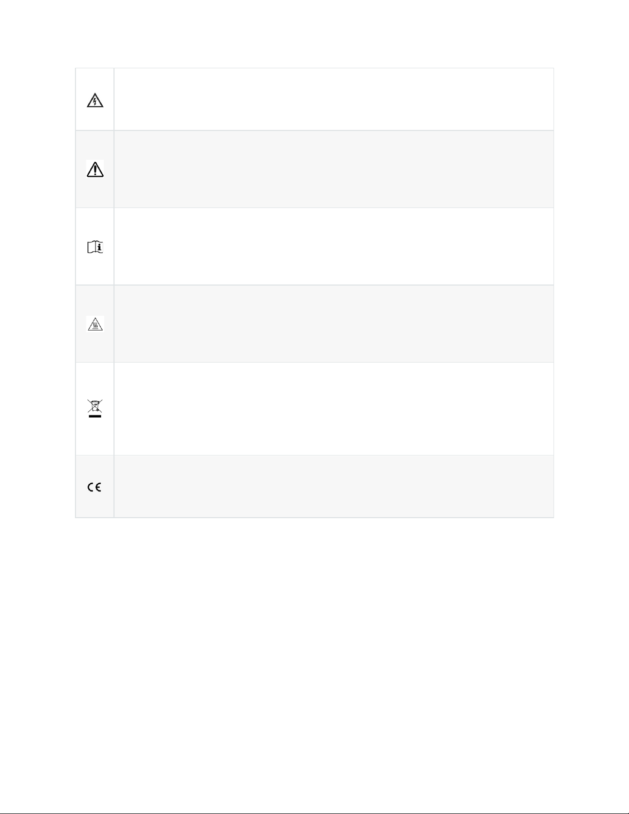
Label is located on the side of the inverter. The information on the label includes technical data as well as
type and serial number of the device. Safety instructions are listed and explained below:
Danger!
The term “danger” describes an issue which, if ignored can cause personal injury.
Attention!
With the term “attention” a circumstance is listed which may cause property damage if
disregarded.
Instructions for use!
Under “Instructions for Use“, it is pointed out that installation and operating instructions are
to be read and understood before installation or repair.
Caution, hot surface!
Under “Caution, hot surface”, it should be noted that surfaces of equipment may be hot and
create a burn hazard.
Special disposal instructions!
With “Note Separate Disposal”, it is pointed out that this product may not be disposed of
with normal garbage. An improperly conducted disposal can lead to damage to the
environment.
CE mark
The product complies with essential requirements of relevant directives of EU
INSTALLING THE PRODUCT
Safety
Danger to life due to fire or explosion
All electrical devices can cause fires despite careful construction. Flying debris from the fire or
explosion may result in death or severe injuries.
DO NOT
install the product in environment with any flammable materials or gases.
DO NOT
install the product in environment with any potentially explosive items or gases.
Risk of injury due to weight of product
Lifting the product incorrectly or dropping in transportation or mounting may result in injuries like
bruises or muscle strains.
Make sure to take the weight of product into account in transportation and lifting, and proceed
carefully.
To avoid muscle strain or injury, please use proper lifting techniques and any necessary
aid/tools.
Personal protective equipment
MUST
be worn suitably and properly for all work.
Risk of injury due to cables routed in wall
Drilling holes on a wall may damage power cables or pipes for gas or water routed inside.
Make sure to take cables or pipes into account before drilling.
Personal protective equipment
MUST
be worn suitably and properly for all work.
Risk of shortened product lifespan due to inappropriate installation environment
Installing the product in an inappropriate environment may risk shortening its lifespan. To ensure
optimal performance and operation, please:
DO NOT
install the product in exposure to direct sunlight.
DO NOT
install the product in exposure to rain and snow.

DO NOT
install the product in exposure to splash of salt water.
Make sure the installation site meets ventilation requirement of the product.
The pollution degree of the external environment for NEP's inverters is
PD3
.
Pollution Degree 3 indicates:
Conductive pollution occurs, or dry, non-conductive pollution occurs which becomes conductive
due to condensation which is expected.
Lightning Surge Suppression
Lightning does not actually need to strike the equipment or building where PV system is installed to
cause damage. Often, a strike nearby will induce voltage spikes in the electrical grid that can
damage equipment. micro inverter has integrated surge protection, greater than most inverters.
However, if the surge has sufficient energy, the protection built into the micro inverter can be
exceeded, and the equipment can be damaged.
Since the NEP Limited Warranty does not cover “acts of God” such as lightning strikes, and since
lightning strikes can occur anywhere, it is best practice to install surge protection as part of any
solar installation. Installation of surge protection devices should follow vendor instructions.
Procedure of Mounting
1.
Attaching the micro inverter Micro inverter on PV module frame or fix on wall with expansional
screw.
2.
Connecting the micro inverter Micro inverter wiring harnesses.
3.
Grounding the system (optional).
DC circuits of micro inverter are isolated and insulated from ground. An integrated ground
protection circuit is included in the micro inverter.
CONNECTING & Commissioning
Safety: Electrical Connections
Danger to life due to electric shock
DO NOT
touch any live component.
TO
prevent risk of electric shock during installation and maintenance, please make sure that the AC
and DC inputs are plugged out.
DO NOT
stay close to the instruments while there is severe weather
conditions including storm, lightening etc.
DC Connection
Safety: Connecting DC
Danger to life due to electrical shock when live DC cables or components are touched
High DC voltages are present in the DC cables when PV modules are exposed to light. Touching live
DC cables or components may result in death or severe injuries due to electric shock.
DO NOT
touch non-insulated parts or cables.
DO NOT
touch live components when voltage sources are still connected or just disconnected.
DO NOT
connect DC connectors to the product under load.
Personal protective equipment
MUST
be worn suitably and properly for all work on the
product and the system.
Voltage sources
MUST
be disconnected from the product before all work.
Danger to life due to electrical shock from touching ungrounded components or from
touching live components in case of a ground fault
Touching ungrounded PV modules, array frame, inverter or live system component, or parts of the
system components that are still live in the event of a ground fault, may result in death or severe
injuries due to electric shock.
PV modules and the array frames, including electrically conductive surfaces,
MUST
be
connected and grounded in compliance with all applicable regulations.
In the event of a ground fault,
DO NOT
touch any parts or frame of the PV array.

DO NOT
touch any cables without reliable insulation.
DO NOT
connect the product to any strings with ground faults.
Before working on the product, voltage resources
MUST
be disconnected.
Personal protective equipment
MUST
be worn suitably and properly for all work.
Risk of injury and property damage
In connection of DC cables to the inverter, maximum input current and voltage
MUST
not exceed
permitted range as stated in Product Parameters.
Any guarantee and warranty claims in such cases will be voided.
DC Connection Procedure
Completely install all micro inverter and all system inter-wiring connections prior to installing the PV
modules.
1.
Mount the PV modules above their corresponding micro inverter. Each micro inverter comes with
two oppositely sexed DC connectors.
2.
First connect the positive DC wire from the PV module to the negatively marked DC connector (male
pin) of the micro inverter. Then connect the negative DC wire from the PV module to the positively
marked DC connector (female socket) of the micro inverter. Repeat for all remaining PV modules
using one micro inverter for each module.
Removing DC
Safety: Disconnection
Danger to life due to electrical shock when live components are touched in opened product
High voltages and energies are present in live components and cables inside the product during
operation, e.g. capacitors, connectors. Touching live components and cables may result in death or
severe injuries due to electric shock.
DO NOT
open the product.
DO NOT
touch live components.
The product
MUST ONLY
be opened for maintenance reasons by a qualified person, after
both DC and AC switches or isolators, if any, externally connected or integrated, are switched
to OFF
both DC and AC connections are plugged out
voltages inside the product are fully discharged
Danger to life due to electrical shock when live DC cables or components are touched
High DC voltages are present in the DC cables when PV modules are exposed to light. Touching live
DC cables or components may result in death or severe injuries due to electric shock.
DO NOT
touch non-insulated parts or cables.
DO NOT
touch live components when voltage sources are still connected or just disconnected.
DO NOT
connect DC connectors to the product under load.
Personal protective equipment
MUST
be worn suitably and properly for all work on the
product and the system.
Voltage sources
MUST
be disconnected from the product before all work.
Risk of injury due to weight of product
Lifting the product incorrectly or dropping in transportation or mounting may result in injuries like
bruises or muscle strains.
Make sure to take the weight of product into account in transportation and lifting, and proceed
carefully.
To avoid muscle strain or injury, please use proper lifting techniques and any necessary
aid/tools.

Personal protective equipment
MUST
be worn suitably and properly for all work.
Procedure of Disconnecting
Before any work on the disconnection of the inverter,
ALWAYS
disconnect it from all voltage sources in
the described sequence as following.
1.
Disconnect the AC by opening the branch circuit breaker.
2.
Disconnect the first AC connector in the branch circuit.
3.
Cover the module with an opaque cover.
4.
Using a DC current probe, verify there is no current flowing in the DC wires between the PV module
and the micro inverter.
5.
Care should be taken when measuring DC currents, most clamp-on meters must be zeroed first and
tend to drift with time.
Do not pull on the cable
.
Instead, use the disassembly tool for PV connectors at the point of interconnection of female
and male connectors.
Pull out the connectors in a downward direction.
6.
Use a suitable measuring device to ensure that
no voltage
is left at the DC inputs of the inverter.
7.
Disconnect the PV module DC wire connectors from the micro inverter.
8.
Remove the micro inverter from the PV array racking.
9.
Use a suitable measuring device to ensure that
no voltage
is left at the AC inputs.
Measure the voltage by inserting the probe to the opening of each terminal.
Check the voltages between L and N, and between L and PE.
10.
If necessary, remove the M5 screw securing the inverter to mounting bracket. Lift the inverter from
the mounting bracket.
Dispose of the inverter should be in accordance with disposal regulations for electronic waste. Refer to
Recycling and Disposal.

Re-install micro inverter
1.
Attach the replacement micro inverter to the PV module racking using hardware recommended by
your module racking vendor
2.
Redo Monitoring Configuration
3.
Connect the AC cable of the replacement micro inverter.
Monitoring Configuration
WiFi configuration
1.DO NOT CONNECT AC
In the state of DC connected, AC disconnected, AP mode of the microinverter will be activated.
If AC connected by accident, please unplug AC, DC to wait for memory clearance of the microinverter.
2.Find the AP Number
An eight-digit string can be found under the barcode on the sticker.
This is the Gateway S/N
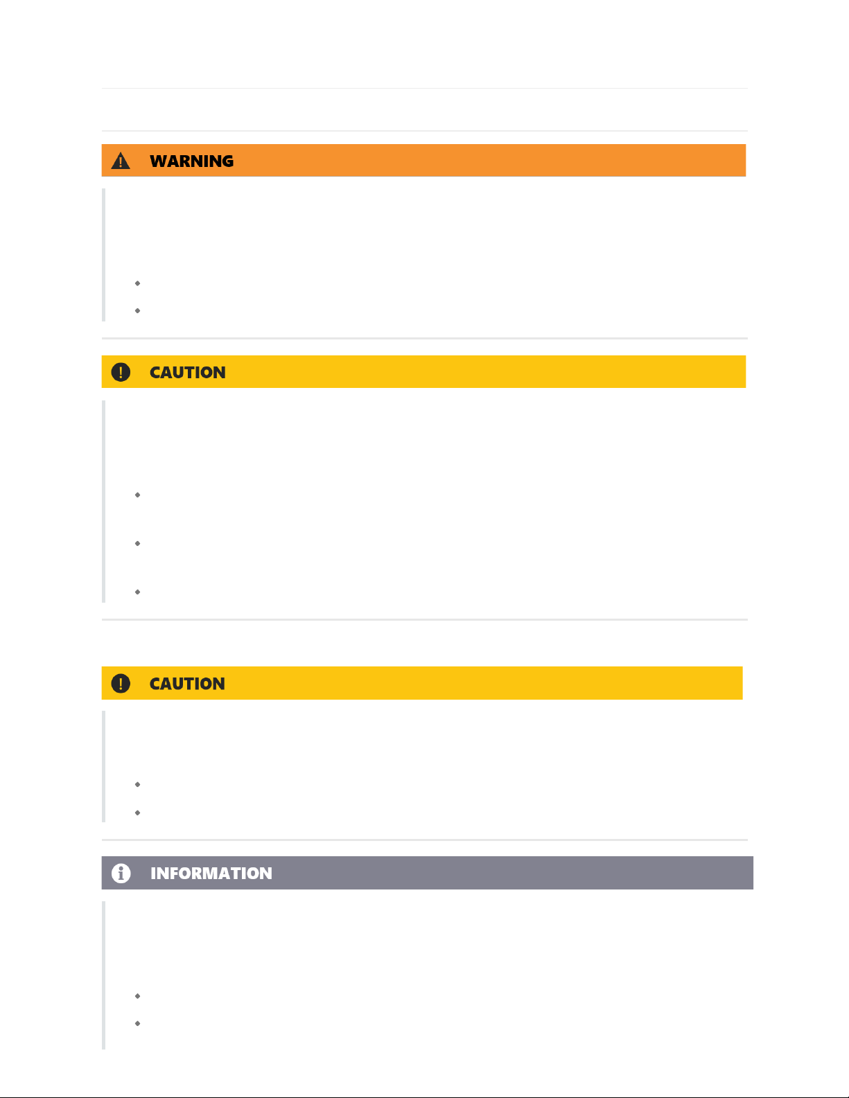
Step 1 Get and Open NEPViewer
1.Obtain NEPViewer App
Search for NEPViewer in App Store or Google Play
(*Android users can visit user.nepviewer.com for latest version APK file)
2.Open NEPViewer
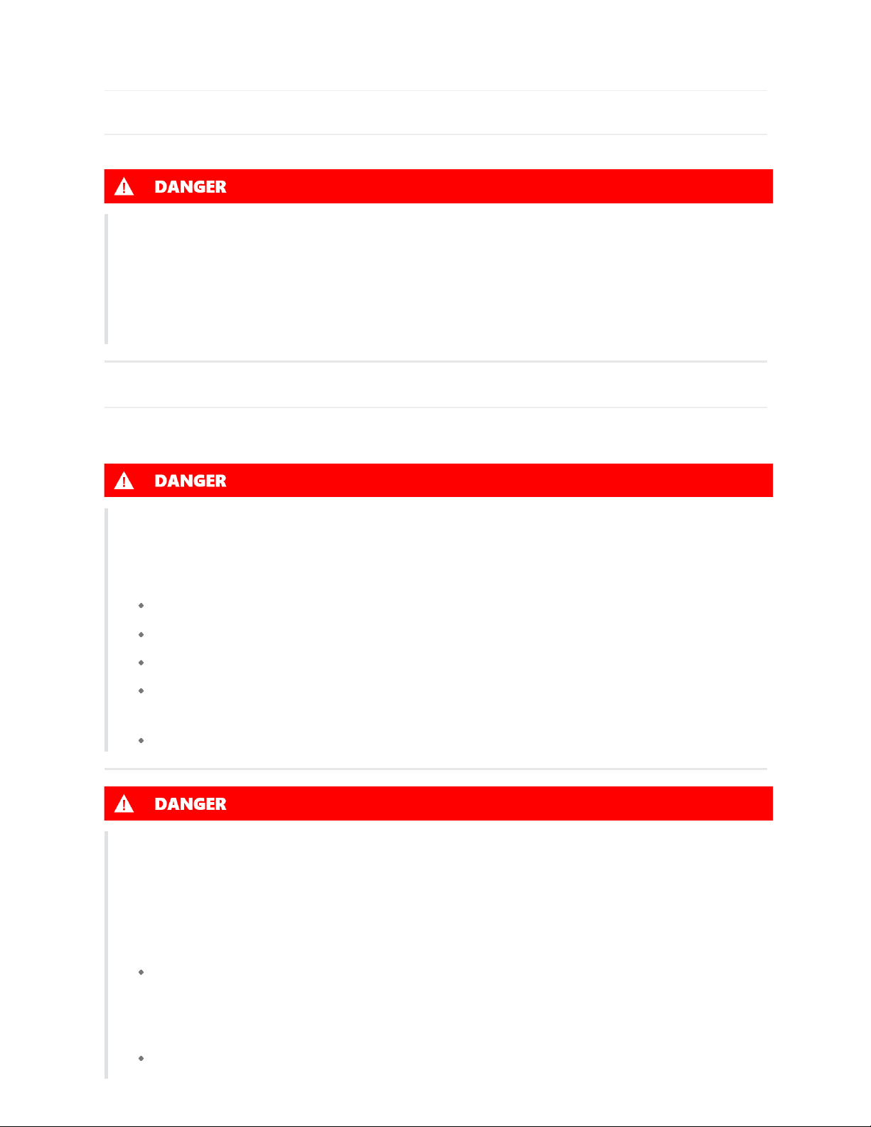
Step 2 Enter NEPViewer WiFi Configuration
Select the distribution network entrance
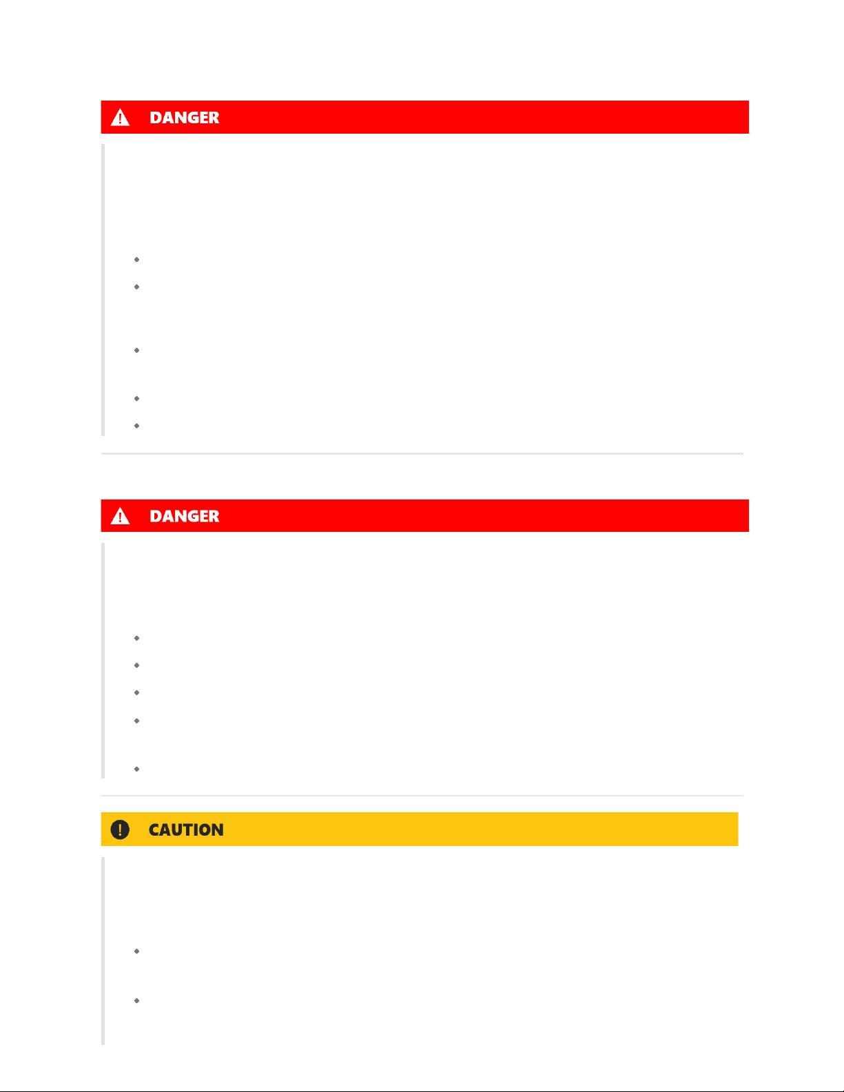
Step 3 NEPViewer WiFi Configuration
1.Click to enter the distribution network
2.Click Allow to obtain geographic location permission (only pops up when installing the app for the first time)
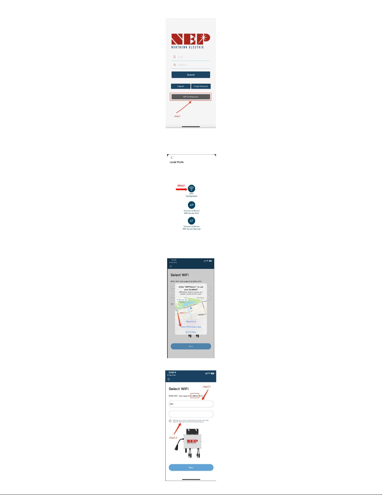
3.Please enter the home WiFi name (the current connected WiFi will be obtained by default)
4.Please enter the password of your home wifi (manual input is required)
This manual suits for next models
3
Table of contents
Other NORTHERN ELECTRIC Inverter manuals


Popular Inverter manuals by other brands
 manual ")


Hoymiles
Hoymiles MI-1000T user manual

Hyundai
Hyundai N700 Series instruction manual

Champion Global Power Equipment
Champion Global Power Equipment 201122 quick start guide

Hyundai
Hyundai DHY18KSEm Operation and maintenance manua

Epever
Epever SHI2000 user manual

Goodwe
Goodwe EHB Series Quick installation guide


