NORTHERN ELECTRIC CM Series User manual
N.E.-C
. ·
739
MANUAL
'
MAY
1958
CONTENTS .
SECTION 1
·DESCRIPTION
& SPECIFICATIONS
SECTION 2 • IN.
ST
ALLA
TION & OP E_
RA
TION ·
.SECTION 3 • ACCESSORIES
SECTION 4
·APPLICATION
NOTES
SEC110N ·s
·SERVICE
INFORMATION
SECTION 6 -
www.telephonecollectors.info ©Jeff Lamb

N.E.•C.
705
WARRANTY
N.
orthern
Electric
Company
Limited
warrants
this
equipment
to
be
free
~rom
defec~s
in
material
and
•
workmanship
under
normal
use
and
service,
its
obligation
under
this
warranty
being
limited
to
shipp-
ing
a
replacement
for
any
numbered
part
or
parts
thereof,
except
vacuum
tubes,
which
.
shall
within
ninety
(90)
days
from
the
date
of
purchase
of
such
equipment
by
the
original
retail
purchaser
be
re-
turned
to
Northern
through
its
distributor
or
dealer
with
tr
ans
port
at
ion
charges
prepaid,
and
which
-examination
shall
disclose
to
Northern's
satisfaction
to
have
been
thus
defective,
such
replacement
will
be
shipped
charges
collect;
this
warranty
being
ex-
pressly
.
in
lieu
of
all
other
warranties
expressed
or
implied,
and
Northern
neither
assumes
nor
author-
izes
any
representative
or
other
person
to
assume
for
it
any
other
liability
in
connection
with
the
sale
of
_its·
products.
·
This
w'
arranty
shall
not
apply
to
any
equipment
\yhich
shall
have
been
repaired
or
altered
in
any
way
so
as,
in
Northern's
opinion,
to
affect
its
stability
or
re-
liability,
nor
to
any
equipment
which
has
been
sub-
jected
to
misuse
,
neglect
or
accident,
nor
to
any
equipment
which
has
had
the
serial
number
altered;
effaced
or
removed.
"Northern
Electric
r
..
ser~es
the
right, without
notice,
to make
such
changes
in equipment,
design,
or
component.,
as
progress
in
e·
ngineering
or
manufacturing
methods
may
warrant."
Northern
Electric
COMPANY
LIMITED
BELLEVILLE,
ONTARIO
.
ASSOCIATED
DISTRIBUTORS:
CANADA-
DOMINION
SOUND
EQUIPMENTS
LIMITED,
4040
ST
. CATHERINE
ST.
WEST,
MONTREAL
u.s.A
.-ALTEC
LANSING
CORPORATION,
1Sl5
s.
MANCHESTER
AVENUE
,
ANAHEIM,
CALIFORNIA
FOREIGN
(EXCEPT
U.S
.
A.)-
WESTREX
CORPORATION
,
111
EIGHTH AVENUE,
NEW
YORK
11
,
U.S.A.
www.telephonecollectors.info ©Jef Lamb
N . E . •
C.
•
741
DESCRIPTION:
Northern
Electric
CM
MAGNAPHONE
PART
II
lss
.
1-5
/58
SECTION 1·
PAGE I
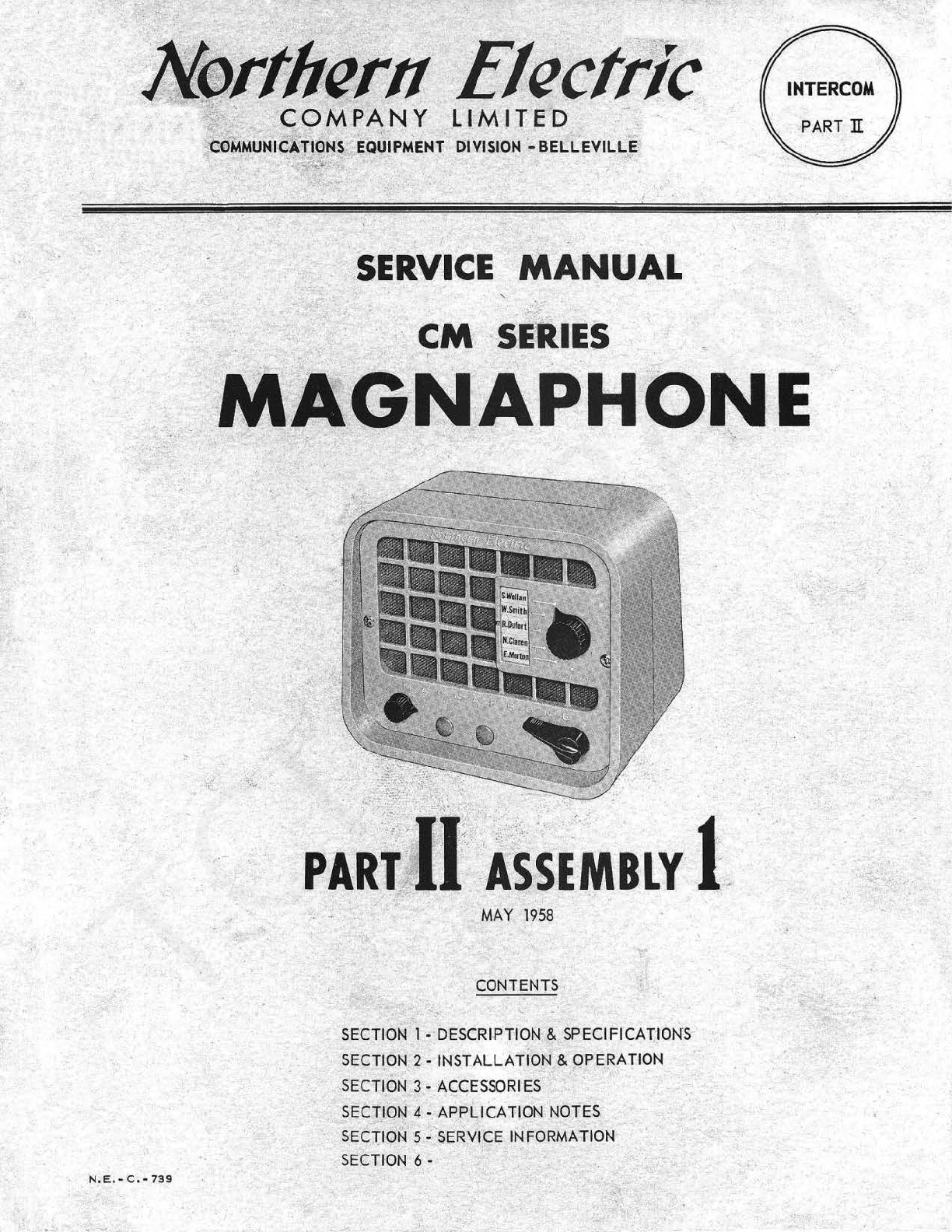
The
Complete Master Magnaphone
is
an economical and
efficient
loudspeaker
intercom
sys-
tem which
provides
intercommunication
facilities
fo
r
industries
,
offices,
institutions
and
homes.
The
cabinets,
suitably
styled
for
office
and home
use
as
well
as
industrial
applicat
i
ons,
are
built
to
withstand
years
of
rugged
use
and
yet
retain
their
original
appearance
.
All Master System
(6
stations
maximum)
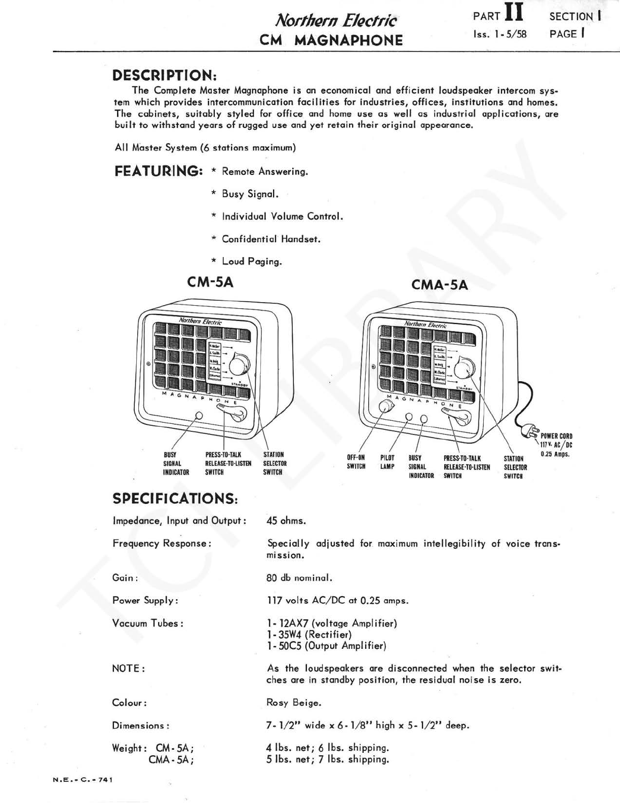
FEATUR·ING: * Remote Answering.
*
Busy
Signal.
* Individual Volume Control.
* Confidential
Handset
.
*
loud
Paging
.
CM-SA
BUSY
S
IGNAL
INDICATOR
PRESs-TO
·
TAL
K
RELEASE
·
TO·LISTEN
SWITCH
SPECIFlCATIONS:
Impedance, Input and
Output:
STATION
SELECTOR
SWITCH
45
ohms.
OFF
·
ON
SWITCH
PILOT
LAMP
CMA-SA
BUSY
SIGNAL
INDICATOR
PRESs-TO·TALK
RELEASE
·
TO·LISTE
N
SWITCH
STATION
SELECTOR
SWITCH
POWER
CORD
\
117v
.
AC
/
De
0.
25
Amp
s.
Frequency
Response
:
Specially
adjusted
for maximum
intellegibility
of
voice
trans
-
mission
.
Gain:
Power Supply :
Vacuum
Tubes
:
NOTE :
Colour:
Dimensions :
Weight : CM-
SA;
CMA-SA;
80
db nominal.
117
volts
AC/
DC
at 0.
25
amps.
1- 12AX7
(voltage
Amp
Iifier)
1-
35W4
(Rectifier)
1-50C5
{Output Amplifier)
As
the
loud
speakers
are
disconnected
when
the
selector
swit-
ches
are
in
standby
position,
the
residval
noise
is
zero.
Rosy
Beige
.
7•
1/
2"
wide x 6 •
1/
8"
high x
5-
1/2"
deep.
4
lbs
.
net;
6
lbs.
shipping.
5
lbs
.
net;
7
lbs
.
shipping
.
www.telephonecollectors.info ©Jef Lamb
PART
II
SECTION I
lss.
1-
5/
58
PAGE 2
N
.E
.
-C
,-
74 2
Northern
Electric
CM MAGNAPHONE
BLANK
PAGE
www.telephonecollectors.info ©Jef Lamb
N.E.-C
.
-743
INSTALLATION:
Northern
Electric
CM MAGNAPHONE
PART
II
lss.
l -5/ 58
SECTION 2
PAGE I
The
two
following
basic
systems
are
presented
to
illustrate
the
installation
of
a
Complete
Master
System.
Both
systems
use
the
same
basic
units,
without
modification,
and
a
choice
of
either
system
will
be
dependant
upon
requirements
and
,
building
arrangement.
The
number
of
stations
used
in a
system
will
depend
on
the
number
of
locations
desiring
intercommunication
and
may
vary
from a minimum
of
two
to
a maximum
of
six.
Although
a CMA- SA
Master
Station
(amplifier
unit)
may
be
placed
at
any
point
from A
to
F
in
either
system,
it
is
suggested
it
be
located
in a
position
where
its
operator
will
be
in
control
of
the
system
and
turn
the
unit
on
and
off
at
the
beginn
ing
and
ending
of
each
day
. It
is
also
recommended
that
it
be
located
near
an
AC
outlet
.
CAUTION -FOR SYSTEMS "A"
(,
"B":
h
is
essential
that
twisted
pairs
be
used
for
station
interconnection.
Each
twisted
pair
should
be
connected
to
a
pair
of
odd
and
even
numbered
terminals,
e.g.
one
pair
for
terminals
l
and
2,
another
pair
for 3
and
4,
another
pair
for 5
and
6
etc
.
Individual
conductors
in
each
twisted
pair
must
not
be
cross
connected.
That
is,
odd
numbered
terminals
are
connected
with
one
conductor
of
a
twisted
pair
and
even
numbered
terminals
are
connected
with
the
other
con-
ductor
of
that
same
twisted
pair
.
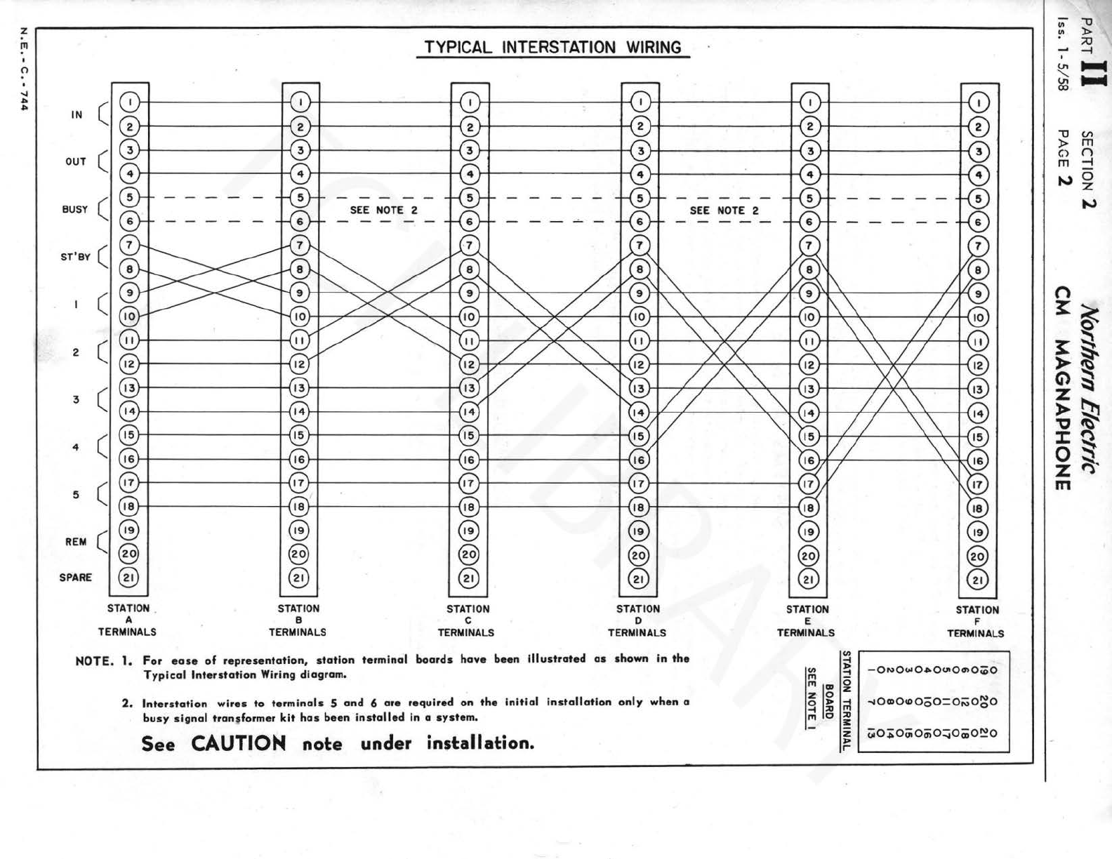
SYSTEM
"A"
:
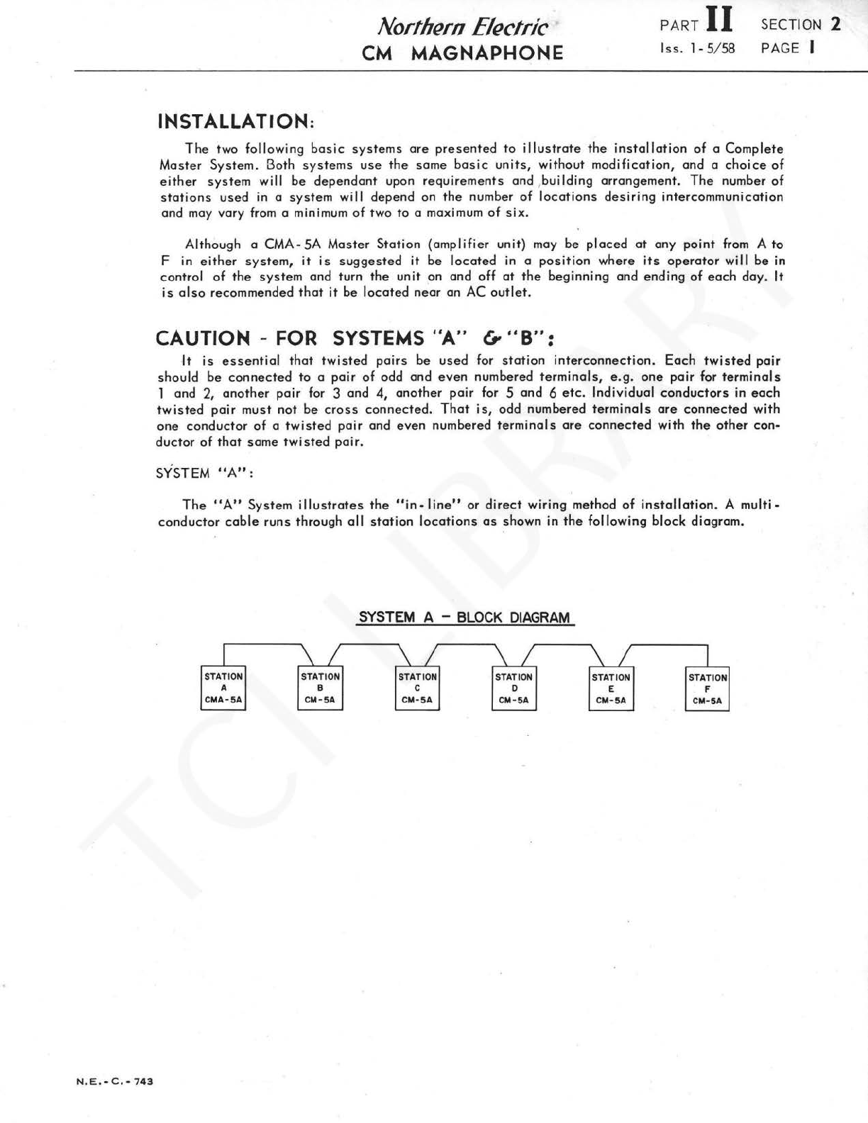
The
"A"
System
illustrates
the
"in-
line"
or
direct
wiring
method
of
installation.
A
multi-
conductor
cable
runs
through
al
I
station
locations
as
shown
in
the
fol
lowing
block
diagram
.
STATION
A
CMA-5A
STATION
B
CM-5A
SYSTEM
A -
BLOCK
DIAGRAM
STATION
c
CM-5A
STATION
D
CM-5A
STATION
E
CM
-
5A
STATION
F
CM
-
5A
www.telephonecollectors.info
©Jef Lamb
~I
....
'"
..
TYPICAL INTERSTATION
WIRING
II
r-1
r----1
r:-i
r-1
r-1
IN
"-1
(?
? ? ? ? ?
"\
I
OUT I
I~
I
l~I
I
':::::::
t I
':::::::
I I
':::::::
I I
"="
I
- - - - -
t<xJt
- - - - -
t<xJt
- - - - -
i-\Vt
- - - - -
~I
SEE NOTE 2 ,-.....
,-.....
SEE NOTE 2
2
3
4
5
REM c @
@
@
SPARE
STATION .
A
TERMINALS
STATION
B
TERMINALS
STATION
c
TERMINALS
STATION
D
TERMINALS
NOTE.
1.
For
ease
of
representation,
station
terminal
boards
hove
been
illustrated
as
shown
in
the
Typical
lnterstotion
Wiring
diagram.
2.
lnterstotion
wires
to
terminals
S
and
6
ore
required
on
the
initial
installation
only
when
a
busy
signal
tron,former
kit
hos
been
installed
in
a
system
.
See
CAUTION nol:e under insl:allal:ion.
- - -
@
@
@
STATION
E
TERMINALS
(/)
-I
@
@
@
STATION
F
TERMINALS
(/)
~
I -ON0<>1041>0UIOOIO(OO
,.,
-
,.,
llJJ
~
~
g
-1
I
....
oa>oioooo=o;\;o~o
-I
:a
,.,
,., c
:a
;::
~
I
t;iO:j;OUiOOiO::;jO(ijO~O
I
Ill
"1J
I !"
)>
;;o
....
-i
I
VI
.....
~
.....
CX>
I I
iJ
(/")
)>
m
II
fri
g
11
..,,
0
z
..,,
n
~~
g
~~
>~
Gl
~
~~
,,
~
:c
g.
~
~·
m
www.telephonecollectors.info ©Jef Lamb
N.E.•C.•745
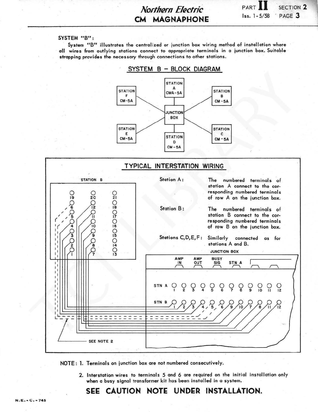
SYSTEM
"B"
:
Northern
Electric
CM
MAGNAPHONE
PART
II
.SECTION 2
lss.
1·5
/58 . PAGE 3
System
"B"
illustrat
es
the
centralized
or junction box wiring method
of
installation
where
all
wires
from
outlying
stations
connect
to
appropriate
terminals
in a junction box.
Suitable
strapping
provides
the
necessary
through
connections
to
other
stations
.
STATION
B
0 0
20
21
0
18
/ 0
SYSTEM B - BLOCK
DIAGRAM
STATION
F
CM-5A
STATION
E
CM-SA
STATION
A
CMA-5A
BO
X
STATION
D
CM-SA
STATION
B
CM-SA
STATION
c
CM-SA
TYPICAL
INTERSTATION
WIRING
Station
A:
The numbered
terminals
of
stat
ion A
connect
to
the
cor·
responding numbered termi
nals
of
row A on
the
junction box.
17
0
( / /
Station
B:
The
numbered
terminals
of
station
B
connect
to
the
cor·
responding numbered
terminals
of
row B on
the
junction box.
'(
I
, 1
11
, 1
, 1
11
I
16
0
15
0
14
0
13
Stations
C,D,E,
F:
Similarly connected
as
for
stations
A and B.
AMP
IN
r\
JUNCTION
BOX
AMP
BUSY
OUT
SIG
STN A
r\
r\
r\
r\
STN A 0 0 0 0 0 0 0 0 0 0 0 0
I 2 3 4 5 6 7 8 9
10
11
12
STN B
f)
f:}
I
'--~-++++----------!-----"
4 / 5 / 6
'----++++-++-------
--
-4-
--
-----'
/ /
LL---
===========
======
==-::...~
_/
~=S=E=E=N=O=T=E=2==========::t:==========================:::::::._/
NOTE·: 1.
Terminals
on junction box
are
not number
ed
consecutively
.
2.
lnterstation
wires
to
terminals
5 and 6 are required on
the
initial
installation
only
when a
busy
signal
transformer
kit
has
been
installed
in a
system.
SEE
CAUTION NOTE UNDER INSTALLATION.
www.telephonecollectors.info

PART.
II
lss.
1·5
/58
AMP
IN
r---\
STN
AO 0
SECTION 2
PAGE4
AMP
BUSY
OUT
SIG
;--\.
I\
0 0 0 0
'
Nortnern
Electric
CM
MAGNAPMONE
CM
SERIES
JUNCTION BOX
CALLING
CIRCUITS
TO
STN
A I
STN
B
STN
C
STN
D
STN
E
STN
FI
;--\.
I\
I\
;--\.
;--\.
I\
0 0 0 0 0 0 0 0 0 0 0 0 0
I 2 3 4 5 6 7 8 9
10
II
12 13
14
15
16
17
18
l9
REM
POS"'I
STN
e O 0 0 0 0 0 0 0 0 0 0 0 0 0 0 0 0 0 0
I 2 3 4 5 6 9
10
7 8
II
12
13
14
15
16 17
18
20
STN
CO
0 0 0 a 0 0 0 0 0 0 0 0 0 0 0 0 0 0
I 2 3 4 5 6 9
10
II
12
7 8
13
14
15 16 17 18 19
REM
POS
12
STN
o0 0 0 0 0 0 0 0 0 0 0 0 0 0 0 0 0 0 0
I 2 3 4 5 6 9
10
II
12 13
14
7 8
15
16 17
18
20
STN
EO
0 0 0 0 0 0 0 0 0 0 0 0 0 0 0 0 0 0
I 2 3 4 5 6 9
10
II
12 13
14
15
16
7 8
17
18 19
REM
POS
"3
STN
F0 0 0 0 0 0 0 0 0 0 0 0 0 0 0 0 0 0 0
I 2 3 4 5 6 9
10
.
II
12
13 14
15
16 17
18
7 8
20
OPERATING TABLE
When
installation
has
been made
in
accordance
with system
"A
..
or
"B
..
wiring diagrams,
the
various
station
selector
switch
posit
i
ons
will be
in
accordance
with
the
following operating
table
.
This
table
applies
to
both, Systems A and
B.
OPERATING TABLE
STATION
#(
#2
A ® ©
B © ©
c © ®
D © @
E © @
F
~
®
SW
ITCH
PO
SITION
• 3
....
,
® ©
@ ©
@ ©
© ©
© @
© ®
'
""
!'ii
®
®
®
0
0
©
0
" 1 0
STANDBY
STN SELECTOR SWITCH
Example : Station A
calls
station
D by turning h
is
selector
switch
to
position
3.
MASTER
GAIN
CONTROL :
A
sc
r
ew-driver
adjusted
type
gain
control, which
is
accessible
through a knockout
at
the
rear of
the
CMA-SA Master Station,
is
provided for adjusting
the
system
level.
INTERSTATION CABLE :
A good grade
of
interphone
type
cable,
utilizing colour coded and
twisted
pair wires,
is
re-
commended.
The
length
of
cable
between
stat
i
ons
will determine.
the
wire
size
and
the
following
chart
can
be used for
this
purpose.
Wire
Gauge
22
19
18
16
Recommended
Maximum
Di
stance
Between
Stations
{Busy signal current limi
tation)
500
ft.
1000
ft.
1100
ft.
2000
·
ft
~
N,
E,
• C , •
74
6
www.telephonecollectors.info ©Jef Lamb
Northern
Electric
CM
MAGNAPHONE
PART
II SECTION 2
lss.
1• 5/ 58 PAGE 5
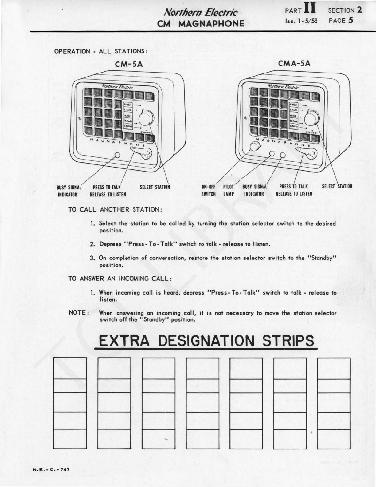
OPERATION -
ALL
STATIONS:
CM-SA
CMA-SA
BUSY
SIGNAL
PRESS
Tll
TALK
SELECT
STATION
ON-OFF
PILOT
BUSY
SIGNAL
PRESS
TD
TALK
SELECT
STATION
INDICATOR
RELEASE
TD
LISTEN
SWITCH
LAMP
INDICATOR
RELEASE
TD
LISTEN
TO
CALL
ANOTHER STATION:
1.
Select
the
station
to
be
called
by
turning
the
station
selector
switch
to
the
desired
position.
2.
Depress
"Press-To
-
Talk"
switch
to
talk·
release
to
listen
.
3.
On
completion
of
conversation,
restore
the
station
selector
switch
to
the
"Standby"
position.
TO
ANSWER
AN
INCOMING
CALL :
1.
When
incoming
call
is
heard,
depress
"Press-To-Talk"
switch
to
talk
-
release
to
listen.
NOTE:
When
answering
an
incoming
call,
it
is
not
necessary
to move
the
station
selector
switch
off
the
"Standby"
position.
EXTRA
DESIGNATION
STRIPS
N.E.•
C.·
747
www.telephonecollectors.info ©Jef Lamb
PART
II
SECTION 2
lss.
1-5
/
58
PAGE 6
N . E .
-C.•748
Nort/Jern
Electric
CM
MAGNAPHON,E
BLANK
PAGE
www.telephonecollectors.info ©Jef Lamb
N.E.
•
C.
•
749
Northern
Electric
CM
MAGNAPHONE
PART
II
lss.
l-S/S8
SECTION
3
PAGE I
ACCESSORIES
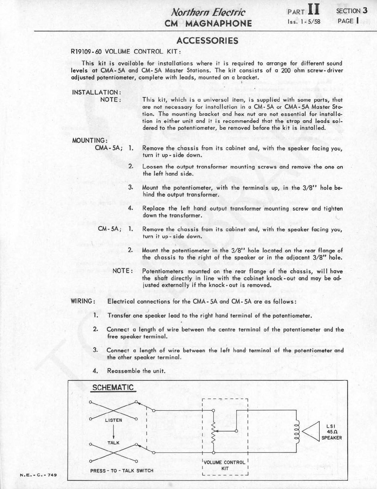
R19109-60
VOLUME CONTROL
KIT:
This
kit
is
available
for
installations
where it
is
required
to
arrange
for
different
sound
levels
at
CMA-SA and CM-
SA
Master
Stations
.
The
kit
consists
of
a 200 ohm
screw-driver
adjusted
potentiometer,
complete
with
leads,
mounted on a
bracket
.
•
INSTALLATION:
NOTE:
This
kit,
which
is
a
universal
item,
is
supplied
with some
parts,
that
are
not
necessa
ry for
installation
in a CM-
SA
or CMA-
SA
Master Sta-
tion.
The
mounting
bracket
and hex nut
are
not
essential
for
instal
I
ci-
tion in
either
unit
and
it
is
recommended
that
the
strap
and
leads
sol-
dered
to
the
potentiometer,
be
removed before
the
kit
is
installed.
MOUNTING:
CMA- SA;
1.
Remove
the
chassis
from
its
cabinet
and, with
the
speaker
facing you,
turn it
up·
side
down.
WIRING:
l.
2.
3.
4.
2.
3.
4.
Loosen
the
output
transformer mounting
screws
and remove
the
one
on
the
left
hand
side.
Mount
the
potentiometer, with
the
terminals
up, in
the
3/8"
hole
be-
hind
the
output transformer.
Replace
the
left
hand
output
transformer 'mounting
screw
and
tighten
down
the
transformer.
CM-SA;
l.
Remove
the
chassis
from
its
cabinet
and,
with
the
speaker
facing you,
turn it
up-
side
down.
2. Mount
the
potentiometer in
the
3/8"
hole
located
on
the
rear
flange
of
the
chassis
to
the
right
of
the
speaker
or in
the
adjacent
3/8"
hole.
NOTE:
Potentiometers
mounted on
the
rear flange
of
the
chassis,
wil I
have
the
shaft
directly
in I
ine
with
the
cabinet
knock·
out
and
may
be
ad-
justed
externally
if
the
knock-
out
is
removed.
Electrical
connections
for
the
CMA-SA and CM-SA
are
as
follows:
J
Transfer
one
speaker
lead
to
the
right
hand terminal of
the
potentiometer.
Connect
a length
of
wire
between
the
centre
terminal
of
the
potentiometer
and
the
free
speaker
terminal.
Connect
a length
of
wire
between
the
left
hand terminal
of
the
potentiometer and
the
other
speaker
terminal.
Reassemble
the
unit.
SCHEMATIC
!
PRESS -TO -
TALK
SWITCH
r----
- - -
-,
I
1
VOLUME CONTROL I
I KIT I
L
_______
_J
<J
LSI
45.n
SPEAKER
www.telephonecollectors.info ©Jef Lamb
PART
II
lss
. 1• S/
58
SECTION 3
PAGE 2
Northern
Electric
CM MAGNAPMONE
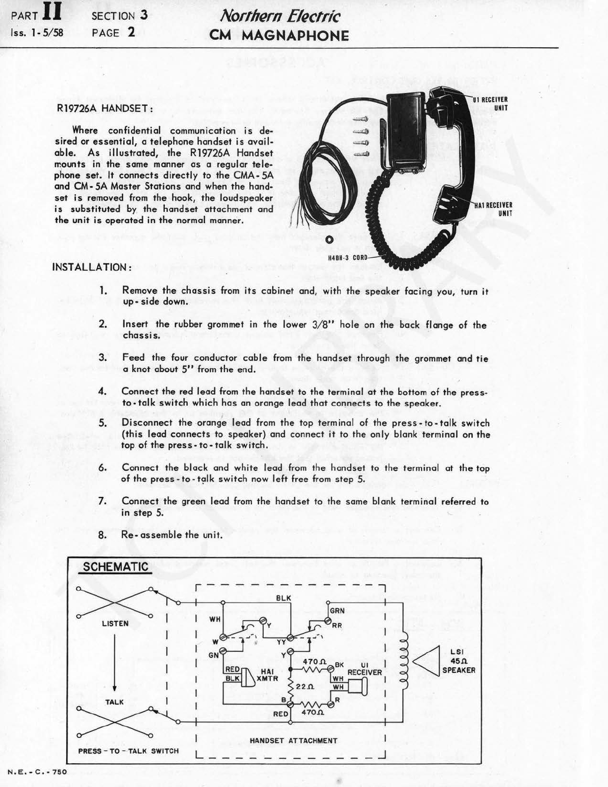
R19726A HANDSET:
U1
RECEIVER
UNIT
Where
confidential
communication
is
de-
s ired
or
essential,
a
telephone
handset
is
ovoi
1-
oble.
As
illustrated,
the
R19726A
Handset
mounts in
the
some
manner
as
a regular
tele-
phone
set.
It
connects
di
rectly
to
the
CMA
·SA
and CM·
SA
Moster
Stations
and when
the
hand-
set
is
removed from
the
hook,
the
loudspeaker
is
substituted
by
the
handset
attachment
and
the
unit
is
operated
in
the
normal manner.
HA1
RECEIVER
UNIT
INSTALLATION :
N.E
.
-C.·7SO
1. Remove
the
chassis
from
its
cab
i
net
and, with
the
speaker
facing
you, turn it
up ·
side
down.
2.
Insert
the
rubber grommet in
the
lower 3/
8"
hole
on
the
bock flange
of
tbe
chassis.
3.
Feed
the
four
conductor
coble
from
the
handset
through
the
grommet
and
tie
a knot
about
S''
from
the
end.
4.
Connect
the
red
lead
from
the
handset
to
the
terminal
at
the
bott.om
of
the
press
·
to
·
talk
switch
which
hos
on
orange
lead
that
connects
to
the
speaker
.
S.
Disconnect
the
·
orang
~
lead
from
the
top
terminal
of
the
press-to-talk
switch
(this
lead
connects
to
speaker)
and
connect
it
to
the
only
blank terminal on t
he
top
of
the
press-to-talk
switch.
6.
Connect
the
block
and
white
lead
from
the
handset
to
the
terminal
at
the
top
of
the
press·
to
-
t~I
k
switch
now
left
free from
step
S.
7.
Connect
the
green
lead
from
the
handset
to
the
some blank terminal referred
to
in
step
S.
8.
Re-
assemble
the
unit.
SCHEMATIC
LISTEN
I
TALK
PRESS
-TO -TALK SWITCH
r - - - -
w
GN
L_
RED
470.Cl
HANDSET ATTACHMENT I
_J
<]
LSI
45.n.
SPEAKER
www.telephonecollectors.info ©Jef Lamb
Northern
Electric
CM
MAGNAPHONE
PART
II
SECTION 3
lss
.
1-5
/
58
PAGE J
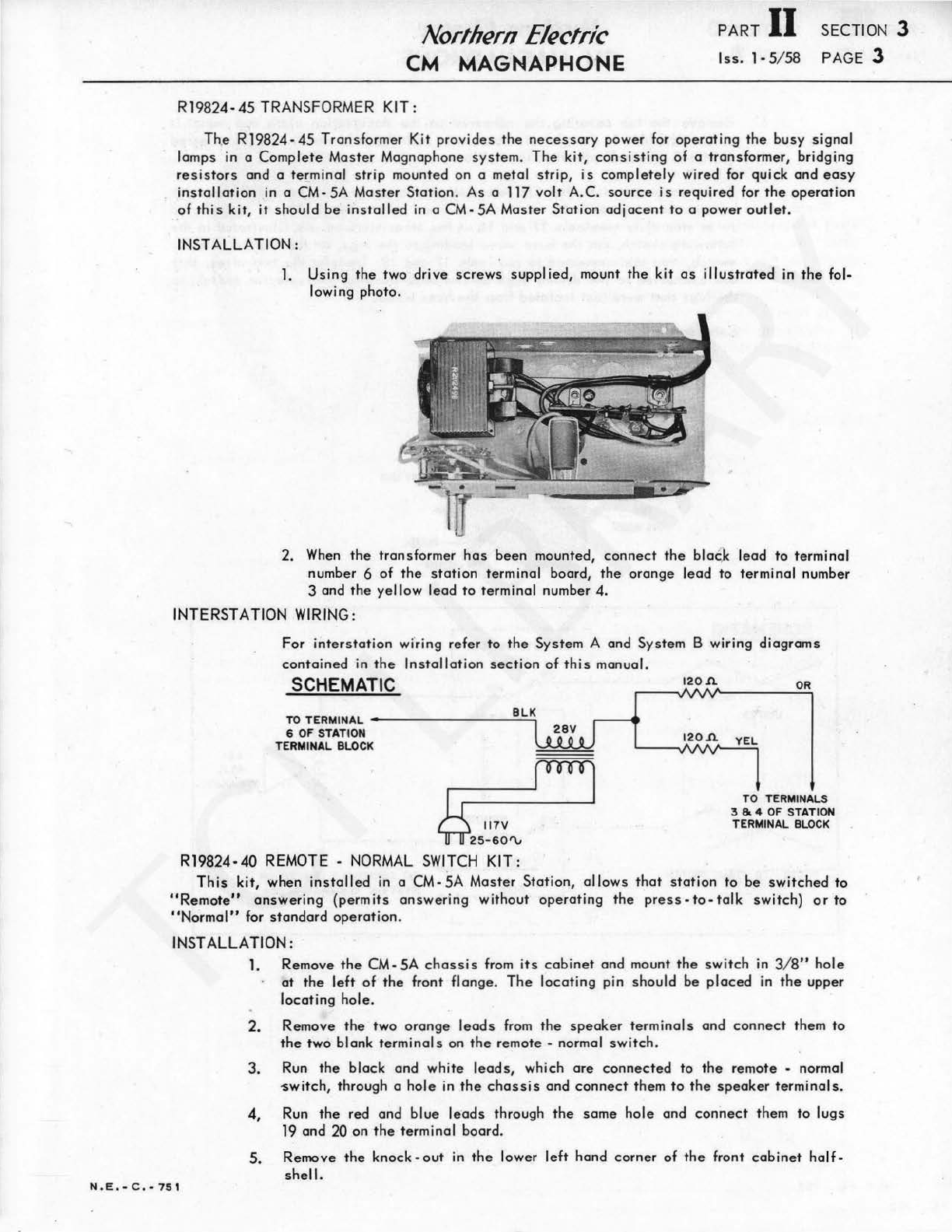
R19824-45
TRANSFORMER KIT :
The
R19824-4S
Tran
sformer Kit
provides
the
necessary
power
for
operating
the
busy
signal
lamps in a
Complete
Moster Magnaphone
system.
The
kit,
consisting
of
a transformer, bridging
resistors
and a terminal
strip
mounted on a metal
strip,
is
completely
wired for
quick
and
easy
installation
in
a
CM-SA
Moster
Station.
As
a 117
volt
A.C.
source
is
required
for
the
operation
of
this
kit,
it
should
be
installed
in
a
CM-SA
Master
Station
adjacent
to
a power
outlet.
INSTALLATION:
l.
Using
the
two
drive
screws
supplied,
mount
the
kit
as
illustrated
in
the
fol-
lowing photo.
2.
When
the
transformer
has
been
mounted,
connect
the
blat
.k
lead
to
terminal
number 6
of
the
station
terminal board,
the
orange
lead
to
terminal
number
3 and
the
yellow
lead
to
terminal
number 4.
INTERSTATION WIRING:
For
interstation
wi'ring
refer
to
the
S
ys
te
m A and
System
B wiring
diagrams
contained
in
the
Installation
section
of
this
manual.
SCHEMATIC
TO TERMINAL
____
___
__
B_L-.K
6 OF STATION
TERMINAL BLOCK
Rl9824-40
REMOTE -NORMAL SWITCH
KIT:
120
.n.
OR
TO TERMINALS
3
&.
4
OF
STATION
TERMINAL
BLOCK
This
kit,
when
installed
in
a CM-SA Moster
Station,
allows
that
station
to
be
switched
to
"Remote"
answering
(permits
answering
without
operating
the
press-to-talk
switch)
or
to
"Normal"
for
standard
operation
.
INST
ALLA
Tl
ON:
N .
E,
-
C,
- 7 S I
1.
Remove
the
CM- SA
chassis
from
its
cabinet
and
mo
unt
the
switch
in 3/
8"
hole
at
the
left
of
the
front
flange.
The
locat
ing pin
should
be
placed
in
the
upper
locating
hole
.
2.
Remove
the
two
orange
leads
from
the
speaker
terminals
and
connect
them
to
the
two
blank
terminals
on
the
remote
-normal
switch.
3.
Run
the
block
and
white
leads,
which
ore
connected
to
the
remote -normal
-switch, through a
hole
in
the
chassis
and
connect
them
to
the
speaker
terminals
.
4, Run
the
red and
blue
leads
through
the
same
hole
and
connect
th
em
to
lugs
19 and 20
on
the
terminal
board.
5. Remove
the
knock-
out
in
the
lower
left
hand
corner
of
the
front
cabinet
holf-
shel
I.
www.telephonecollectors.info ©Jef Lamb
PART
II
lss
.
1-
5/ 58
SECTION 3
PAGE 4
Nortnern
Electric
CM
MAGNAPHONE
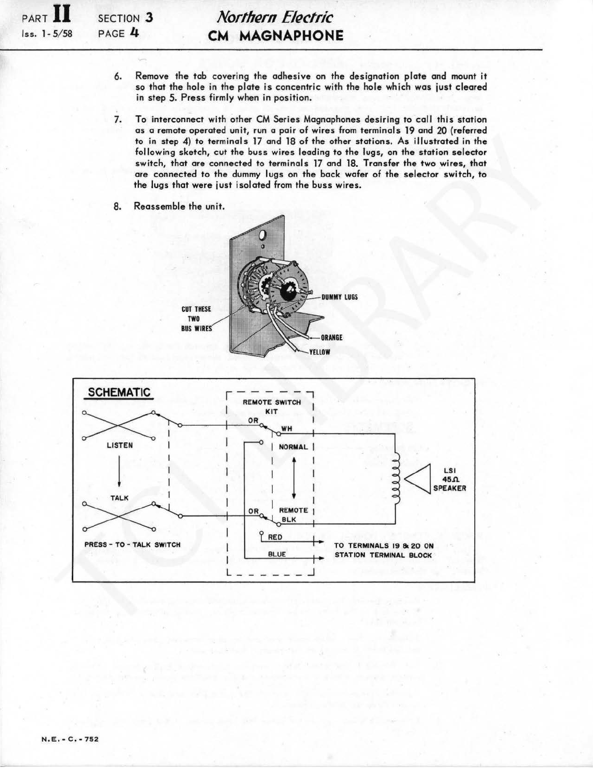
6. Remove
the
tab
covering
the
adhesive
on
the
designation
plate
and
mount
it
so
that
the
hole
in
the
plate
is
concentric
with
the
hole
which
was
just
cleared
in
step
5.
Press
firmly when in
position.
7. To
interconnect
with
other
CM
Series
Magnaphones
desiring
to
cal
I
this
station
as
a remote
operated
unit, run a
pair
of
wires
from
terminals
19
and 20 (referred
to in
step
4)
to
terminals
17
and 18
of
the
other
stations.
As
illustrated
in
the
fol lowing
sketch,
cut
the
buss
wires
leading
to
the
lugs, on
the
station
selector
switch,
that
are
connected
to
terminals
17
and 18.
Transfer
the
two
wires,
that
are
connected
to
the
dummy
lugs on
the
back
wafer
of
the
selector
switch,
to
the
lugs
that
were
just
isolated
from
the
buss
wires.
8.
Reassemble
the
unit.
SCHEMATIC
CUT
THESE
TWO
BUS
WIRES
I
-RE;OT;
SWIT;
',
I
KIT
"0-~~~-+~-0~R:.:.o..
I
f'O'W~H"-~+-~~~~~~
LISTEN
J
TALK
NORMAL I
lI
I
I
~~~~-+-~rO~R-'0-.
REMOTE I
BLK
?
RED
PRESS
-TO -TALK
SWITCH
I•
BLUE
L - -_J
<J
LSI
45A
SPEAKER
TO
TERMINALS
19
8c
20
ON
STATION TERMINAL
BLOCK
N.E.-C.
•
752
www.telephonecollectors.info ©Jef Lamb
N.E
.
-C.•753
Nort/Jern
Electric
CM
MAGNAPHONE
APPLICATION NOTES
(RESERVED)
PART
II
SECTION 4
lss
.
1-
5/ 58 PAGE I
www.telephonecollectors.info ©Jef Lamb

BLANK
PAGE
www.telephonecollectors.info ©Jef Lamb

N.
E.
• C
...
751
Northern
Electric
CM
MAGNAPHONE
SERVICE INFORMATION:
Pl2
S3
CM-
SA
TOP
VIEW
S2
Pt2
BUSY
SIGNAL
LAMP
HO
L
DER
CM-SA
BOTTOM
VIEW
BUSY
SIGNAL
LAMP
HOLDER_-.
I
\ I
PL2-'"'
Tl
R4
Yl
\
LSl
R12
RS
PLl
CMA-SA
BOTTOM
VIEW
PART
II
SECTION
5
lss.
1·5
/
58
PAGE
I
R14
,
R15
C6
S2
S3
CMA-SA
TOP
VIEW
www.telephonecollectors.info
©Jef Lamb

z
"'
0
--I
(II
O>
LSI
4~
.ll.
SPEA
l5£
R
TO
MODIFIED
SWITCH
POS
I
TION
TERMINALS
DN
CALLING
STATION
t t
$·
~
I I
-
~
"
1·-
--
..0
·1
:
o--!-J
,--------
• '
Bl.
Kl
af"
I I
C_J
VOLUME
CONTROL
KIT
Rl9109-60
I
I
_
.;J.w
·I
R
470.n.
RED
I
I
I
I
·1.
L_
__
~
"
-~
-
--~-
-J
OPTIONAL
HANDSET
Rl9726A
HOOK
SWITCH
OPERATION
STAN~
I
-·7:
·
~
IJ
Ii I
~·
Iz I
I I I
I I
I~
I
I 2 I
I~
i
fl_
,_
- I
L
o-
-'---
-_J
____
J
REMOTE
SWITCH KIT
Rl9824
·
40
LISTEN
!
TALK
" I
TO
AMPLIFIER
INPUT
-
I
OUMMY
LUGS
I I
·1
I
~
~
~
0:
~
..
ii:
BUSY
S
IGNA
L
TRANSFORMER
KIT
Rl9B24
·
4~
S3 - IF
'
STBY-
~~~s~1~t
i'
8ft's
~Mi'o7..sOTHER
SWITCH
POSITION
.
o----@--
2
---
o------@--
3-
~J.T:~rOF
f
~1-
'
.=t=:::::::l-
,,_,
•
4_ }
~iT~~LIFIER
~
'
S3-IR
'
f~~-}
~·-
TO
STANDBY
~3
-TERMINALS
OF
-
~
OTHER
STATIONS
.
o---@--2-
1
~1-
TO
OTHER
BUS
Y
LIGHTS
C
AUTION
ODD
AND
EVEN
OIUM8ER
TERMINALS MUST .NOT
BE
CROSS"CONNECTED.
NOTES·
SW
I
TCH
POSITION
TO
THIS STATION'S
<f---:-@-STBY
-
~ll~
&?J
J
~ION
STATIONS
I- ©
REPRE
SENTS TERMINALS
ON
STA
T
ION
TERMINAL
BOARD
.
2· 0 REPRESENTS TERMINALS
ON
HANDSET·
MTG.
BK
3-
WIRING
FROM
SWITCH
•s2"
FOR
ODD
TE~MIN
A L
CIRCUITRY
IS
COLOURED
ORANGE;
WIR
I
NG
FROM
SWIT
CH •
s2"
FOR
EVEN TERMINAL
CIRCUITRY
IS
COLOURED
YELLOW.
4·
DOTTED
LI
NE
S I
NDICATE
AS
SOCIATED.
WIRING
ADDEO
WITH
KITS.
SWIT
CHBANK
SCHE
M
ATIC
·
Cll
Cll
~
~
""O
)>
;:o
~
...
...
'
"'U
(/)
)>
m
G)
()
m
~
...,
~
u.
n
~~
~~
,...
f
(i)
~
z
,...
~
,,
~
:c
~
o~
z
~
'
m
www.telephonecollectors.info
©Jef Lamb
·z
fl!
0
I
....
Ill
!" • n SI A
12AX7
50C5
117
VOLTS
A.C./D.C. 5 9 4 4
TO
STN. TERM.
CD
TO STN. TERM. ®
AMPLIFIER
INPUT
3
200.n
5W
RED
RED
Rll
33.n
V3
35W4
5
RI
6.8
MEG
.
+I
133 V. •
VI
12AX7
C6.I
401150
Rl2
210.n
v
2W
-..J_.
C6.2
T
40
/150
Rl3
4.
7K
R6
IOOK
R7
I
MEG
.
C4
I .
0047/400
-..J_. C6.3
+-r
401150
8
2
It)
.....
08
llOV
.
RS
470K
7
T2
Rl9650A
V2
50C5
C7
5/40V
.
I.
• • • • • • • •
..
A
C2
l
.047/600
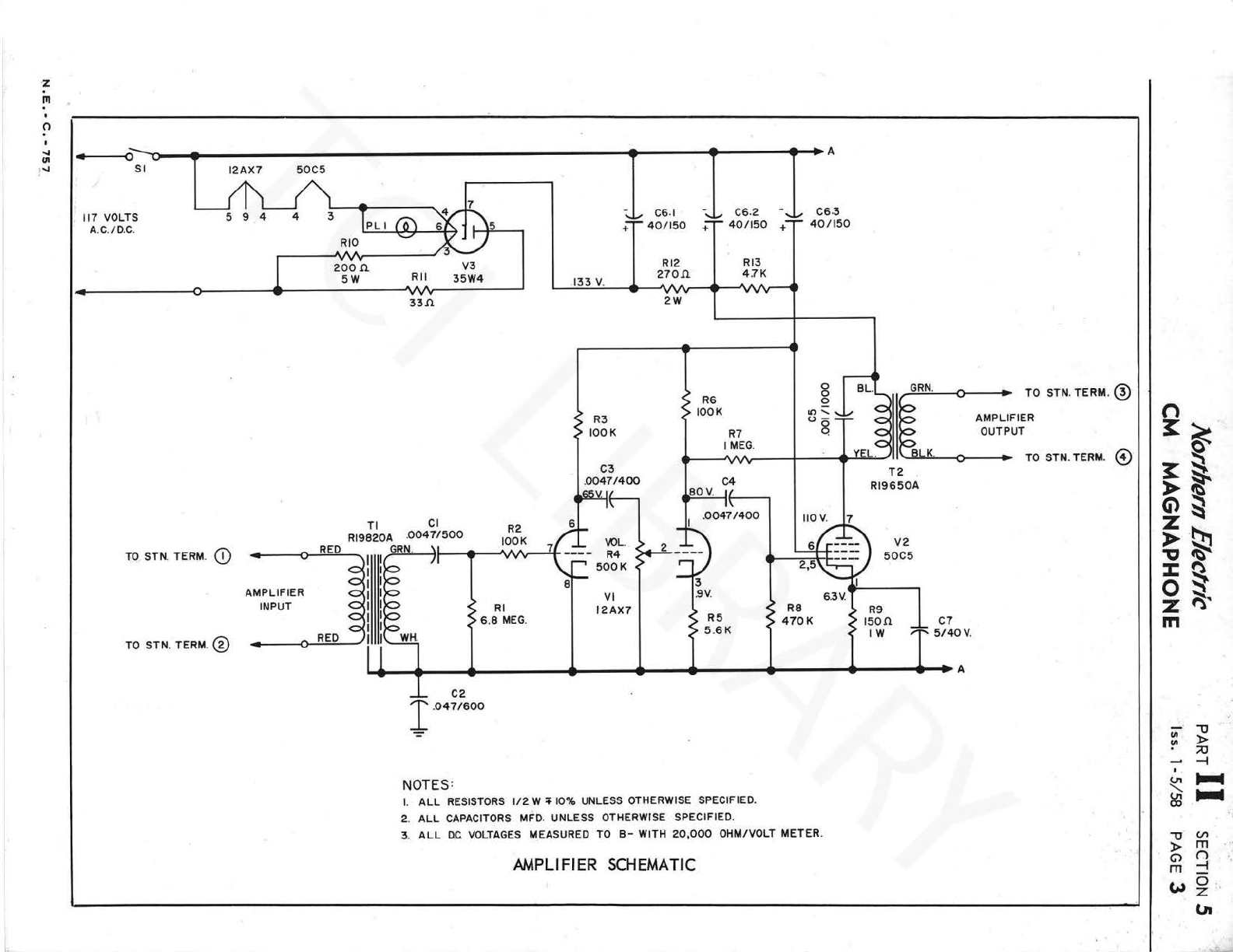
NOTES:
I.
ALL
RESISTORS
112
W
40
10% UNLESS OTHERWISE SPECIFIED.
2.
ALL
CAPACITORS
MFD. UNLESS OTHERWISE SPECIFIED.
3.
ALL
OC.
VOLTAGES
MEASURED
TO
B-
WITH
20
,
000
OHM/VOLT METER.
AMPLIFIER SCHEMATIC
TO
STN.
TERM
. @
AMPLIFIER
OUTPUT
TO
STN.TERM. ©
n
~~
g
~~
,...
~
Ci)~
~
·
~
-a~
:c:
~
0
~
z
m
(/I
""O
!" >
;;o
-l
~
.....
~
.....
""O
(I\
> m
C>
()
m
-l
~o
z
VI
www.telephonecollectors.info ©Jef Lamb
PART
II
lss. l -5/ 58 SECTION 5
P
AG
E 4 .
Nort/Jern
Electric
CM
MAGNAPHONE
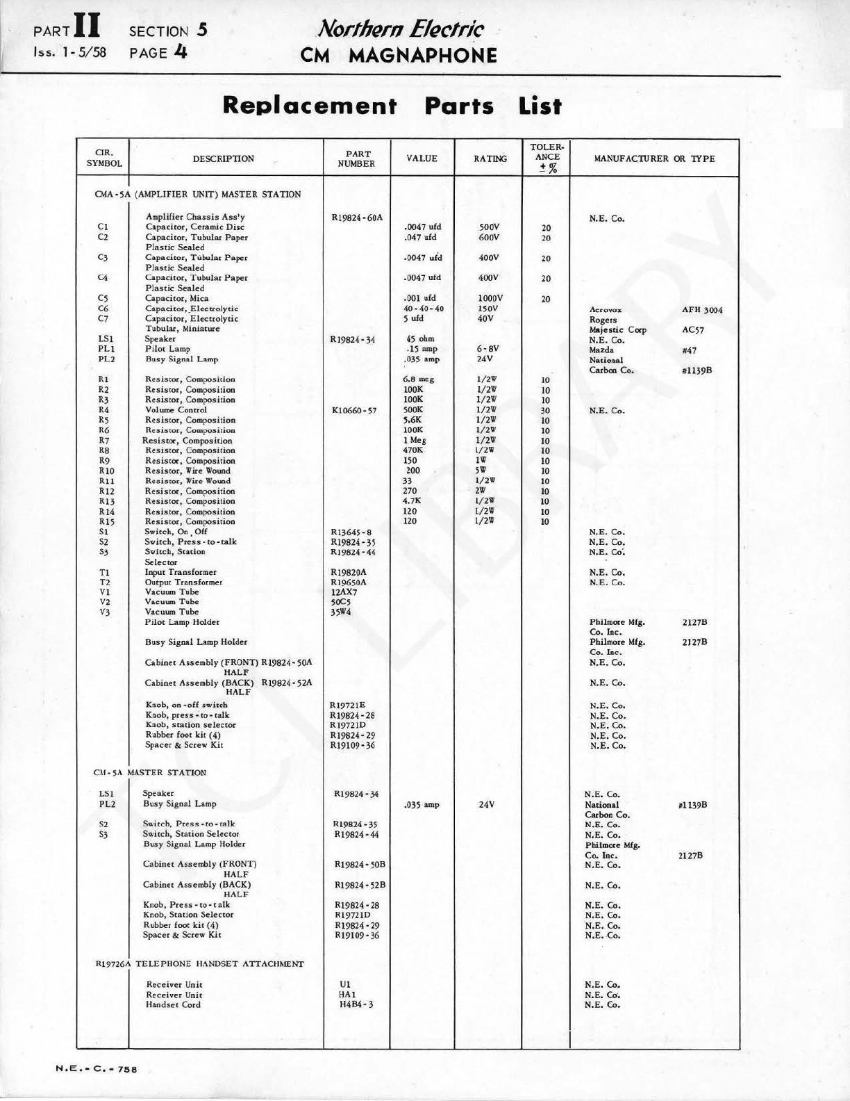
Replacement
Parts
CIR. DESCRIPTION
PART
VALUE RATING
SYMBOL
NUMBER
CMA-5A (AMPLIFIER UNIT) MASTER STATION
Amplifier
Chassis
Ass,y
RJ9824-60A
Cl
Capacitor,
Ce
ramic
Disc
.0047 ufd 500V
c2
Capacitor,
Tubular Paper .047 ufd
600V
Plast
ic
Sea
l
ed
C3 Capacitor, TUbular
Pape
r
.0047
ufd 400V
Plastic
Sealed
C4 Capacitor, Tubular
Paper
.0047 ufd 400Y
Pl
astic
Sealed
C5 Capacitor, Mica .001 ufd
lOOOV
C6 Capacitor, .El
ectrolytic
40-40-40 150V
C7
Capacitor,
Electro
l
ytic
5 ufd 40V
Tubular,
Mi
niature
LS!
Spea
ker R!9824· 34 45 ohm
PL!
Pilot
La
mp .15 amp 6 -
sv
PL2
Busy
Signal Lamp .035 amp 24V
Rl
Resistor,
Co
m
position
6.8
m
eg
l/2W
R2
Re
sis
tor, Composition
!OOK
l/2W
R3
Resistor,
Composition
l
OOK
l/2W
R4 Volume
Control
Kl0660
·57 500K
l/2W
R5
Resistor,
Compositio
n 5,6K l/2W
R6
Resistor,
Composition
!OOK
l/2W
R7
Resis
t
c:x,
Composition
l
Meg
l/2W
RS
Resi
stor, Composition 470K l/2W
R9
Resi
stor, Compo0
sition
150
!W
RlO
Resistor,
Wire
Wound
200
5W
Rll
Resistor,
Wire
Wound
33
l/2W
Rl2
Resistor,
Composition 270
2W
Rl3
Resis
tor, Composition 4.
7K
l/2W
Rl4
Resistor,
Composition 1
20
l/2W
R!5
Resistor,
Compos
ition
120
l/2W
Sl
Switch,
On Off
Rl3645-8
S2
Switch,
Pre
0
ss
-
to
-talk
Rl9824-35
S3
Switch,
St
ation
Rl
9824-44
Selector
Tl
Input Transformer
Rl9820A
T2
Output
Transfo
r
mer
Rl9650A
VI
Vacuum
Tu
be 12AX7
V2 Vacuum Tube 50C5
V3
Vacuum Tube 35w4
Pi
l
ot
Lamp
Hold«
Busy
S
igna
l Lamp Holder
Cabi
n
et
Asse
mbly (FRONT)
Rl9824-
50A
HALF
Cabinet
Asse
mbly (BACK)
Rl9824-52A
HALF
Knob, on ·
off
sw
itch Rl9721E
Knob,
press•to•talk.
Rl9824·
28
Kn
ob,
station
selector
R!
972!D
Rubber foot
kit
(4)
R!9824·29
Sp
acer
& Scr
ew
Kit
R!
9109·36
CM
-
5A
MASTER
ST
ATION
LS!
Speaker
Rl9824
-34
PL2 Busy Signal Lamp .035 amp 24Y
s2
Swit
ch,
Pre
ss
-
to
· talk Rl9824 -35
S3
Swi
t
ch,
Station
Selector
Rl9824·44
Busy
Signal Lamp Holder
Cabinet
A
ss
embly (FRONT) Rl
9824·
50B
HALF
Cabinet
Assembly (BACK) RJ
9824·52B
HALF
Knob, Pr
ess
-to
-
talk
R!9824 -28
Knob,
Station
Selector
Rl9721D
Rubber foot
kit
(4)
Rl9824
-29
Space
r & Screw Kit
Rl9109
-36
Rl9726A
TELEPHONE
HANDSET ATTACHMENT
Receiver
Unit Ul
Receiver
Unit H
Al
H
andset
Co
rd
H
4B4-3
N.
E . • C , • 7
58
List
TOLER-
ANCE
~
%
MANUFACTURER OR
1YPE
N.E.
Co.
20
20
20
20
20 Aerovox AFH 3004
Rogers
Majestic Cocp AC57
N.E.
Co.
Mazda #47
National
Carbon
Co.
11'
11
39B
10
10
10
30 N.
E.
Co.
10
10
10
10
10
10
10
10
10
10
10 N.
E.
Co.
N.E.
Co.
N.E.
co·.
N.E
.
Co.
N.
E.
Co.
Philmore
Mfg.
2127B
Co. Inc.
Philmore
Mfg.
2127B
Co
.
Inc.
N.
E.Co.
N.E
. Co.
N.E.
Co
.
N.E.
Co.
N.
E.
Co.
N.
E.
Co.
N.
E.
Co.
N.E. Co.
National ltl
1398
Carbon
Co.
N.E.
Co
.
N.E.
Co.
Pbilmore
Mf
g.
Co
.
Inc.
2127B
N.E. Co.
N.E.
Co.
N.
E.
Co.
N.E.
Co
.
N.E
.
Co.
N.E•.
Co.
N.E.
Co.
N.E.
Co·.
N.E.
Co.
I
www.telephonecollectors.info ©Jef Lamb
This manual suits for next models
2
Table of contents


